Building a Quadrifilar Helix Antenna for Undergraduate Researchers
←
→
Page content transcription
If your browser does not render page correctly, please read the page content below
Building a Quadrifilar Helix Antenna for
            Undergraduate Researchers

                                                         Introduction
                                                         There are many different antenna designs for
                                                         capturing images from weather and other low-
                                                         level, non-geosyncronous satellites. Most of
                                                         these designs focus on extended range,
                                                         receiving signals over large arcs, but having null
                                                         spots directly overhead or at other inopportune
                                                         locations. The ideal solution to this problem is
                                                         the extremly effective and efficient Quadrifilar
                                                         Helix Antenna.

                                                         The Quadrifilar Helix Antenna (QHA) is a simple
                                                         and inexpensive solution to the problem of non-
                                                         geosynchronous satellite research. This antenna
                                                         is unique in its simplicity of design and powerful
                                                         performance compared with standard
                                                         directional receivers. Once relatively
                                                         anonymous, this incredible tool has gained
                                                         attention recently in many different fields and is
                                                         particularly valuable for the Global Positioning
                                                         System (GPS).
                                           1

While the theory behind such a fantastic antenna is quite complicated, here it has been simplified in
order to fascilitate understanding of its construction. For further understanding of antenna theory or the
Quadrifilar Helix Antenna in particular, see either Antennas by John D. Kraus or the article in ARRL “The
W3KH Quadrifilar Helix Antenna” by Eugene F. Ruperto (listed as superscript 1 throughout this guide for
reference purposes)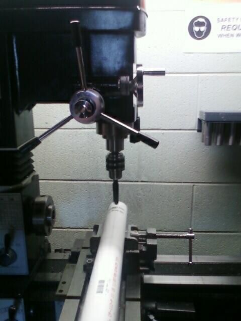
Parts List
Materials Tools
BNC attachments for coaxial cable Ruler or tape measure
Electrical tape Permanent marker
Several feet of coaxial cable (this will Calculator
depend on the frequency and size of Pliers
the antenna you wish to build) Wire cutter
Several feet of 1/2 inch PVC pipe Wire stripper
Several feet of 2 or 2.5 inch PVC pipe Drill press or electric drill
Several feet of copper wire or thin X-Acto knife or similar
tubing ( length depends on frequency) Soldering Iron
Solder
Solder removing tool (this can be either
a wick or a “solder sucker” device)
A Brief Introduction to Soldering
Warning! The soldering iron and wire joints will become very hot!
Soldering is a necessary and basic skill for any Electrical Engineer, but
perhaps you have not had enough experience with it. Here is a brief
overview of the proper technique involved in soldering, as well as
examples of good and bad soldering.
Soldering is a method of joining two components electrically. This is accomplished by using a soldering
iron and solder. Solder is a metal alloy with an extremely low melting point and high capillary action.
Often, it contains a resin core which doubles as a flux.
A flux is an acidic substance which serves to slightly etch the surface of whatever component you are
soldering. This is useful because it helps the solder to adhere better to the components.Take note
though, that soldering is an electrical connection, not a structural weld. Soldering is used to make sure
wires will conduct electricity, and will NOT provide substantial strength to a joint.
The first step of soldering is to turn on the soldering iron. There should be a heat control on the power
unit, this is important because too high of a temperature can scorch the components you are trying to
solder, and too low of a temperature will not be enough to make the solder flow.
Once the iron is heated up (this may take several minutes on larger units), you must touch the iron to
the joined components. The goal is to heat the joint untill the solder wire melts on contact with the
joint, NOT ON THE SOLDERING IRON! When the joint is hot enough for the solder to melt, the solder will
melt into the joint and flow into the various nooks and crannies untill the joint is completely covered. If
you fail to heat the joint up enough or only melt the solder on the iron you will leave little drops of
melted solder on the joint. This is known as a cold joint and does not supply the necessary conductivity.
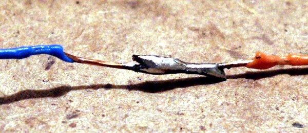
Below are examples of good and bad soldering. Notice the shiny color in the good soldering connection
and the very fluid shape of the solder.
Good Soldering Bad Soldering
If you find you have used too much solder, you can re-heat the joint and apply either a solder wick-
which consists of a braided metal tape- or use a “solder sucker” device which relies on air pressure to
remove liquid solder.
Specific tips for this project
The choice of material for the antenna elements matters greatly. Not on performance, but rather on the
ease of construction for this project. The typical choice of wire is copper. Copper is a good conductor
and is a popular choice for almost every electrical project, however using large wires leads to additional
difficulties. In this case since the wire size is approximately 10 gauge, there is a relatively large amount
of copper which needs to be fitted and soldered together. This is a problem because copper has an
extremely high heat conductivity. For this reason large copper wires will heat up significantly along their
total length before the required joint is hot enough to properly flow the solder.
Aluminum is another possible choice for antenna construction. It is cheaper than copper and less
conductive. This is excellent because it means that the aluminum joint can be heated more easily than a
comparable copper one. This allows an easier construction of the various connections for the beacon.
However aluminum has one large flaw, its tendency to oxidize. Pure aluminum will oxidize in air in
several nanoseconds. The oxide layer is a fairly strong insulator which can lead to electrical connectivity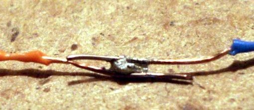
problems. However, due to the extremely thin layer of oxide this can be overcome. The severity of this
drawback depends on the application, but for this project it should not pose a problem.

Before attempting to solder any connections first brush all the parts to be connected with a steel wire
brush, and then apply flux. This will make the process considerably easier if you are using a difficult
medium such as copper, and can speed up the process for easier metals such as aluminum.

          Building the Quadrifilar Helix Antenna
Background Information:
There are a few things that need to be understood before construction can begin on the QHA. Fist and
most important is that the dimensions of the antenna are directly proportional to the frequency you
wish to receive. Second is that the antenna consists of two sets of loops which are different sizes. This is
immensely important as it allows the QHA superior performance by reducing noise and eliminating null
spots.

Also necessary is the basic terminology of a standard coaxial cable. It consist of two parts, an inner core
wire which is insulated with a dielectric (typically a plastic), and an outer metal braiding. If for some
reason you need to splice together a coaxial cable it is a relatively simple matter to connect the core to
another core and the braiding to another braiding.

Now that the basics are covered, let’s examine a completed antenna to understand the parts and
connections you will need later on.

                                                                                           1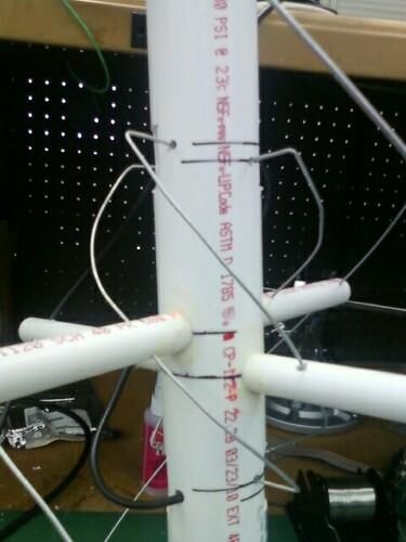
As you can see above, there is a smaller set of armatures located inside of a large set of arms. This is
important as these differences in size will determine what frequency the antenna responds to. The
connections in the figure to the right are quite important. They form an infinite balun- a method of
converting the symmetrical radio signal into a readable impulse to be read by software. One notable
feature of this design is that one of the larger loops is replaced with a length of coaxial cable. This can be
seen in the diagrams above. This is immensely important to the design and must be kept in mind when
measuring the appropriate length of wire.
Stage 1: Crunching the numbers
The very first thing you must do is understand which frequency you need to receive. Since the antenna
you build will be tuned to a single frequency it is vital to consider this first. Additionally, if you plan to
use two QHAs at the same time, it might benefit you to make them inside one another so as to avoid a
phase difference created by difference in position.
The QHA is easily adapted to almost any frequency and a simple cookbook recipe can be assigned to the
various parts. Here are the various values for the antenna segments.
Big Loop Small Loop
Height= 0.26 λ Height=0.238 λ
Diameter=0.173 λ Diameter=0.156 λ
Leg Size=0.560 λ Leg Size=0.508 λ
Step 1: Calculate the wavelength using the following equation. c= λ f
In this equation c is the
8
speed of light (often approximated at 3*10 m/s) f is the frequency and λ is the wavelength. Additionally,
a wire or element diameter of 0.0088 λ is recommended, but failure to use an optimum size will only
decrease gain by a few tenths of a decibel.
Once the various calculations are completed it is time to start gathering materials.
Stage 2: Gathering the materials
Step 2: Gather the necessary materials required by the calculations you have made. Using the example
in the above picture, it would require 84.75 inches of smaller diameter PVC, slightly over 24 inches of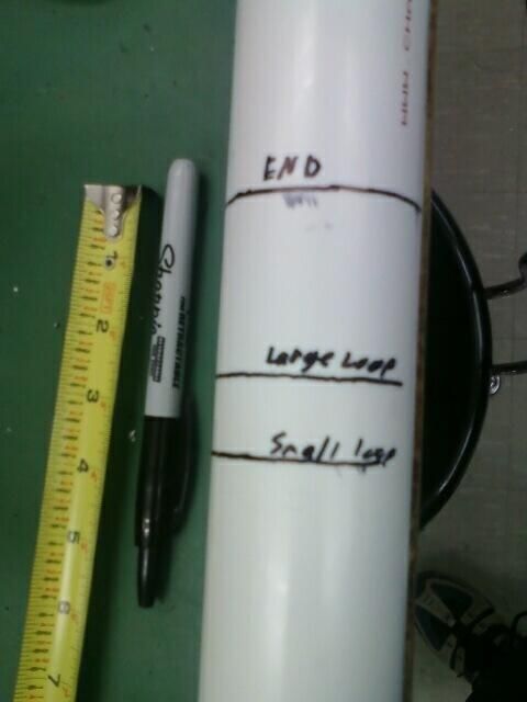
larger diameter PVC, and approximately 10 feet of wire. These materials should be laid out in an easy to
organize fashion, as confusion only breeds mistakes in construction. Below is an example of what the
materials should look like.

                                                                            1

                                                        Stage 3: Measuring the
 Mark the center lines on
                                                        materials
 the central support.                                   Step 3: Leaving a few inches of space at either
                                                        end for structural integrity, mark a starting
                                                        place for the largest loop. This will be the center
                                                        of the hole you will drill for that loop. Now
                                                        measure the distance specified in your
                                                        calculation of “height” and make another mark
                                                        on the PVC. You have now marked the center to
                                                        center distance of your largest loop. At this
                                                        point it is adviseable to trace a line around the
                                                        PVC so that the position is easy to see.

                                                        Step 4: Next, take the difference in heights
                                                        between the loops (that is, subtract the small
                                                        loop height from the large loop height) and
                                                        divide it by two. This is the distance you must
                                                        measure from the largest loop towards the
center of the antenna (lengthwise). This is so that you have an inner loop which is equally spaced from
top and bottom away from the larger loop.
Step 5: As with the large loop, mark a line around the PVC pipe to indicate the center of the small loop.
Measure the height specified in your earlier calculations of small loop height from the measurement you
just made. Mark the spot. Now you have completed marking the vertical distances of the loops.
Step 6: Finally, measure half the vertical distance for each loop and mark a center line around the PVC.
This will be the position of the cross arms which support the antenna in the middle. Measure both
center arm marks from the same end. You will notice
Note the lack of top and bottom
that both of the center arms will be marked at the
supports. This antenna is small enough
same point. This is normal. The center arms will
to not need them.
need to be adjust around the center point by an inch
or so, just enough so that the supports have
clearance through the center. In the case of a dual
QHA, both of the center arms were adjusted by
approximately ½ inch adjacent to the center line. For
more sample measurements on a functioning
antenna, see appendix A.
Additionally, if you are constructing an antenna with
frequency higher than 300 MHz or so, there may be
no need for support arms. In this case continue to
mark as usual, but instead of placing supports in the
center holes, you will be bending the wire into the
center holes in the appropriate shape. For
Caution! It is critical that you measure and cut
the wire to precisely the value calculated in the
Adjacent supports are rotated 90
previous section, otherwise the antenna will not
degrees. This is very important.
be tuned properly.
Step 7: Measure and mark on the wire the
distance marked “diameter” on both ends of the
wire. This will assist you greatly when it comes
time to install it.
Step 8: Finally, pick one spot and use a section of
the pipe you will be using to mark a circle around
the centerline to indicate the drill point. Repeat on
the opposite side being SURE that it is exactlyaligned on the reverse side. Rotate 90° and repeat with the smaller loop.
Step 9: Work your way up the main pipe this way, rotating each time you come to a new center
marking.
Check point: When you are finished marking the support, it should have staggered hole marks and
center lines. The picture to the left is an example of what yours should look like when properly marked.
Stage 4: Constructing the frame
WARNING! NEVER PLACE YOUR HAND BEHIND THE OBJECT YOU ARE DRILLING!
Step 10: The next step is to drill the holes you marked. The easiest way to do
this is with a drill press, but if you do not have acess to one, or do not have the necessary skills to use
one, an electric dril may be used.
Step 11: After all the requisite holes have
been drilled, carefully inspect them to make
Make sure that the pipe is securely
sure there are no extra pieces that would stop
fastened and the drill is positioned
the cross arms from fitting through.
precisely in the middle
Caution! it is important to notice that the
half-point cross beams will be 90° offest from
the end pieces. This means that the large loop
holes for the center brace will be on the same
side as the small loop holes.
Step 12: Insert the arms through the holes
starting from the bottom with a longer arm
meant for the larger loop.
Step 13: Once through, measure to make
sure both sides extending from the larger pipe
are the same length. It is critical that the arms
be positioned precisely in the center or else
the diameter of the helix will be incorrect and
the antenna will not be tuned properly.
Step 14: After all the arms have beenmeasured and adjusted until correct, apply some PVC cement or other adhesive of equivalent strength
in order to prevent the arms from moving. Let this dry for several hours before continuing.
Step 15: After the glue has dried, drill small holes the size of the wire you are using near the end of
each arm, making sure they are positioned at the distance marked “diameter” in your calculations. The
holes should be at approximately a 45° angle left of vertical if viewed from the base. This ensures that
the wires when installed will be able to wind counter-
clockwise around the antenna when viewed from the
bottom.
Step 16: Finally, drill small holes the size of the wire
into the size of the central pipe just above or below the
top and bottom cross pieces. This is for the wire to enter
the central cavity where it can be properly connected.
Bear in mind that one of the larger loops will be made
out of coaxial cable and as such will need a larger set of
holes.
Check Point: At this point the antenna frame should
look like the diagram above. The arms should form a
staggered cross. The longest arms should be located at
the ends of the antenna, and the large loop middle arm
should be the lower of the two middle supports. The
remaining arms should be support for the smaller loop.
If for any reason your antenna is not consistent with the
above diagrams, go back and replace arms or drill new
holes. Creating new holes in the central support will not
affect the performance of the antenna.
1
Stage 5: Wiring the antenna
Step 17: Once all the holes are drilled, you must install the wire. This is most easily done by taking a
straightened wire and feeding it through the holes, only bending the wire when absolutely necessary to
smoothly fit through the cross arms.Step 18: When the markings you made on the wire indicating the correct diameter length are just beyond or at the top and bottom cross piece bend the ends into the center of the pipe for connection. Repeat this for the 3 arms. The 4th one will require less work as it is composed of coaxial cable. Step 19: Solder the connections as shown in the wiring diagram on page 4. It is imperative that they be connected as illustrated or else your antenna will not operate correctly. All the wires at the bottom of the antenna will be connected to the braiding of the coaxial cable, while one of the larger loops at the top and one of the smaller loops will be connected to the center of the cable. Step 20: Once the appropriate connections are made, wrap them in electrical tape or shrink wrap in order to prevent any accidental breakage from movement. Step 21: Finally, mount the BNC connector onto the end of the coaxial cable using the instructions included with the part. However if those are missing it is fairly simple to connect the braiding to the outside of the connector, and the center of the cable to the center of the connector. Congratulations, if all has gone well you are now the owner of a functional Quadrifilar Helix Antenna! Below is an example of a finished Quadrifilar helix antenna with another antenna nested inside it. This is a complicated project which should not be attempted the first time; however a successful build is quite an achievement for any undergraduate researcher.
Appendix A: List of Measurements
A functional QHA was constructed with a smaller nested antenna inside it. These were tuned to 150
MHz and 400MHz. They will be labeled as 150 and 400 respectively. All measurements are in inches,
with 1 inch = 2.54 cm.

Center support length: 25.5

150 Large loop arm length: 15

150 Small loop arm length: 13

All center measurements from bottom of center support

150 Large loop center locations: 2.5 , 11 ¾ , 23

150 Small loop center locations: 3 5/16 , 12 5/8 , 22 1/8

400 Large loop center locations: 9 1/8 , 16 5/8 (note, no additional armature for middle support)

400 Small loop center locations: 9 ¼ , 16 ¼
You can also read