Installation Guide Tundra, Landcruiser and Lexus TVS2650 Supercharger Kit - TOYOTA 3UR-FE SUPERCHARGER
←
→
Page content transcription
If your browser does not render page correctly, please read the page content below
TOYOTA 3UR-FE SUPERCHARGER
    Installation Guide

                      Installation Guide
                 Tundra, Landcruiser and Lexus
                   TVS2650 Supercharger Kit

Page |1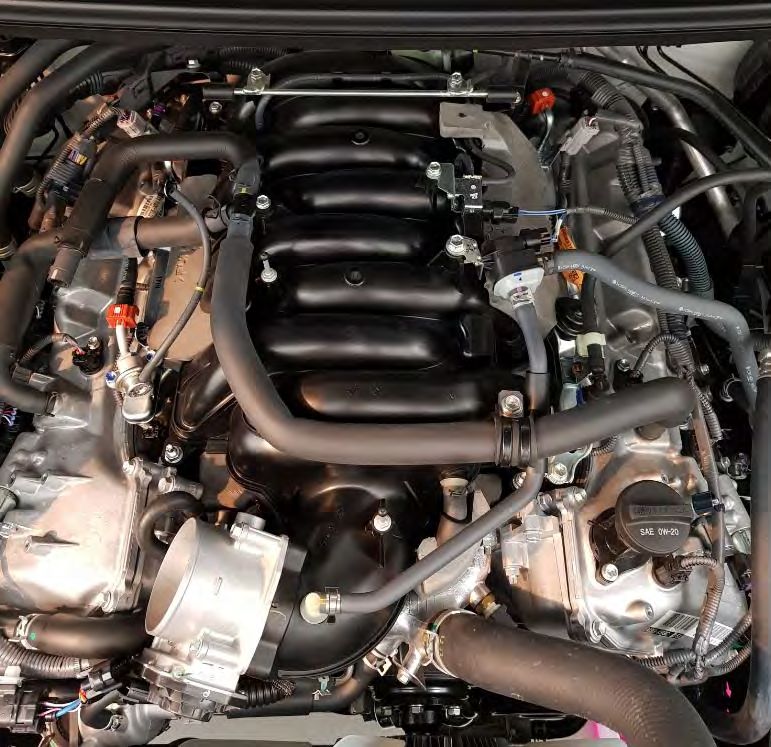
TOYOTA 3UR-FE SUPERCHARGER
      Installation Guide
The Harrop TVS2650 Supercharger kit has been developed for Toyota Tundra, Lexus LX570 and Land Cruiser 200 with
the 5.7 Litre V8 Gasoline engine. This Harrop supercharger kit is not compatible with E85 fuel.

The following part numbers should be referenced when ordering so the correct kit is supplied, as there are subtle
differences in the hardware.

Vehicle Applications

2007 - Current 3UR-FE Tundra             2017 - Current 3UR-FE Landcruiser         2007 - Current 3UR-FE Lexus LX570
                                         200 series

                       Harrop Part
                                                                  Description
                        Number
                  99-KSM51K40           S/Chrg Kit 2650 3UR-FE 5.7 Tundra CARB

                  99-KSM51K41           S/Chrg Kit 2650 3UR-FE 5.7 LC200-LX570 CARB

Harrop 3UR-FE CARB kits are installed without re-calibration of the ECU. 93-AKI (98-RON) fuel is recommended, 91-
AKI (93-RON) fuel may be used as a minimum. Verification of knock control, Air/Fuel ratios and Boost pressure on
dyno is recommended. Refer to the document “Toyota_3UR-FE_V8_Tech_Guide” for information.

This document can be downloaded from:

https://www.harrop.com.au/shop/system/download/190808_Toyota_3UR-FE_V8_Tech_Guide.pdf

This kit is covered by Executive Order (EO) number TBD from CARB.

Preparation
Testing has shown the OE fuel pump (Toyota OEM 232200S011) does not deliver enough fuel for a supercharged
3UR-FE at full load. Therefore, the fuel pump will be replaced during installation. Ensure the fuel tank contains
minimal fuel, and that there is a supply of suitable fuel available to add to the tank after installation is complete. E85
fuel is not compatible.

The fuel pump supplied in this Supercharger kit is DeatschWerks DW300c, 340 Liters of Fuel Per Hour.

RHS of vehicle is from the driver’s perspective when in the driving position.

Allow the engine to cool before starting installation.

Disconnect the battery.

Remove the under tray.

                                                    Contents

Page |2
TOYOTA 3UR-FE SUPERCHARGER
         Installation Guide
Preparation ....................................................................................................................................................................... 2
1)     Install Harrop intercooler radiator – Tundra ............................................................................................................ 4
2)     Install Harrop intercooler radiator – LX570 AND LC200 ......................................................................................... 10
3)     Removal of Toyota Intake Manifold........................................................................................................................ 16
4)     Removal of Toyota Coolant crossover pipe ............................................................................................................ 19
5)     Removal of Toyota Oil Coolant lines ....................................................................................................................... 20
6)     Installation of Harrop Engine Coolant cross-over Pipe ........................................................................................... 22
7)     Installation of the Supercharger idler bracket ........................................................................................................ 23
8)     Installation of the Harrop Supercharger ................................................................................................................. 24
9)     Install Harrop Oil coolant pipe ................................................................................................................................ 26
10)        Install Ancillary hoses and brackets .................................................................................................................... 27
11)        Install wiring patch looms ................................................................................................................................... 29
12)        Install high flow fuel pump ................................................................................................................................. 30
13)        Finalise installation.............................................................................................................................................. 34
14)        CARB certification sticker placement .................................................................................................................. 35
15)        Initial engine start and Calibration...................................................................................................................... 35

Note – For Tundra Installations, follow step 1 and then proceed to step 3. Skip step 2.

            For LX570 and Landcruiser 200 series, skip step 1 and follow step 2 onwards.
All hoses used throughout installation meet the requirements of SAE J20R3, J30R7 or J1037. Hoses are printed with
identification at time of manufacture

Coolant hose - SAE J20R3                                      PCV/EEC hose - SAE J30R7                                      Vacuum hoseSAE J1037
½” Automotive coolant hose: Gates #28400                      ½” PCV/EEC Vacuum hose: Gates #27006                          5/32” PCV/EEC Vacuum hose: Gates #27035
5/16” Automotive coolant hose: Gates #28408                   3/8” PCV/EEC Vacuum hose: Gates #27004
¾” Automotive coolant hose: Gates #28402                      11/32” PCV/EEC Vacuum hose: Gates #27230
Harrop oil cooler coolant hoses: Harrop #14210

Page |3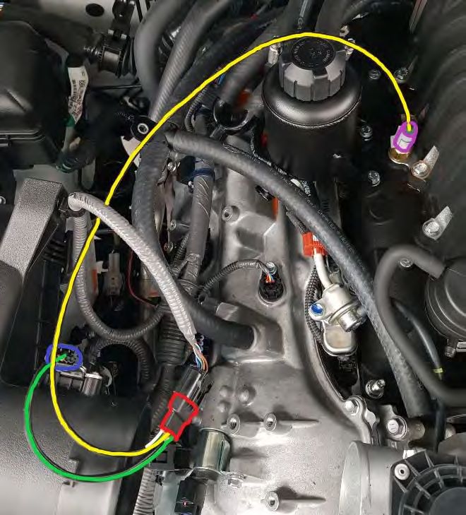
TOYOTA 3UR-FE SUPERCHARGER
      Installation Guide

1) Install Harrop intercooler radiator – Tundra
Remove front Grille by unscrewing the 6x screws across the top of the grille. Pull the Grille forward to dislodge the
clips that secure each lower corner below the headlights.

                                                                     Open access panel and disconnect
                                                                     loom plug underneath

                             Remove 6x screws

Drain the radiator by opening the drain cock on the LHS lower corner of the radiator.

    a) Remove hood latch and strut.
    b) Remove horns.
    c) Unscrew A/C condenser lower brackets. It is not necessary to disconnect any AC system hoses or de-gas the
       AC system.
    d) Unscrew hose bracket from RHS of AC condenser.
    e) Remove A/C condenser upper brackets.

                                                                  1b

                                                                            1a

                                     1e                                                    1e
                                   1d
                                                                                  1c
                                      1c

Page |4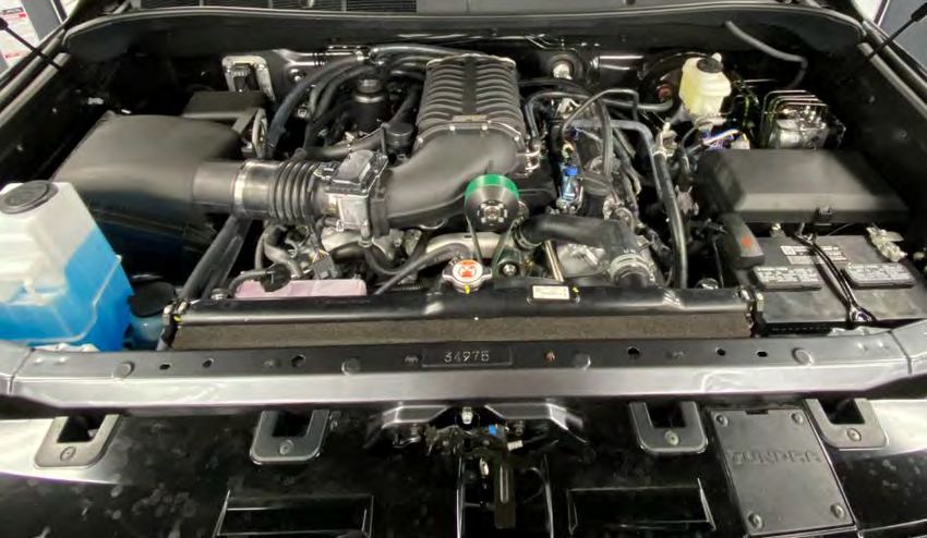
TOYOTA 3UR-FE SUPERCHARGER
       Installation Guide
  f) Swap top A/C condenser bracket rubber bushes to Harrop radiator. Mount the Intercooler radiator onto the
     original pins on the top cross-member (adjacent to the horns).
  g) If the A/C condenser does not have the 2x mounting holes shown below, then mount bracket #14681 to the
     top of the A/C condenser before installing the Intercooler Radiator.

                                                                                                 1g
              1f

  1g
  Use bracket
  #14681 if required

Page |5
TOYOTA 3UR-FE SUPERCHARGER
    Installation Guide
  h) Install top 4x M6 original bolts through intercooler radiator and A/C condenser.
  i) The lower radiator brackets sandwich between the A/C condenser and the OE condenser brackets. Install
     the supplied 4x M6x16 flange head bolts to the lower radiator mounting brackets.
  j) Install hose bracket to RHS of intercooler radiator.

                                                       1h
                                    1h

                              1j

                                       1i            1i

  k) Remove the plastic infill panel from the RHS of the intercooler; it will be modified to allow clearance for the
     intercooler pump.
     i) Cut the infill panel as shown in the image below.
     ii) Re-install the infill panel using the original clips.

Page |6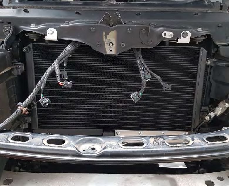
TOYOTA 3UR-FE SUPERCHARGER
       Installation Guide
  l) The intercooler pump bracket mounts to the existing tapped holes in the lateral chassis member
     immediately below the RHS lower radiator mount bracket. Install the bracket using the supplied M8x25
     button head screws through the existing holes as shown.
  m) Install the supplied ¾” x 75mm long hose and 2x #10 hose clamps to the intercooler pump and then onto the
     intercooler radiator outlet as shown below.
  n) Secure the pump to the bracket, allowing 20mm of space between the pump inlet and radiator outlet, using
     2x #32 hose clamps. Orient the pump outlet to point vertically.

                                                            1m
                                 1l

                                                                                     1m

Page |7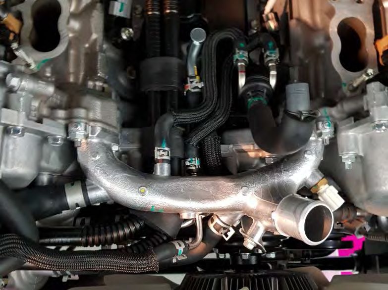
TOYOTA 3UR-FE SUPERCHARGER
    Installation Guide
  o) Connect the supplied intercooler pump loom to the pump and run the loom along the lateral chassis
     member towards the Battery and cable tie it as necessary to secure it. Allow some slack in the loom near
     the pump plug to enable easier disconnection if required.
  p) On the LHS of the intercooler radiator, there is enough space to pass the loom through the LH infill panel
     without cutting it. Route the loom toward the fuse box, located behind the battery.
  q) Remove the fuse box lid.
  r) The intercooler pump loom relay is mounted on the outside of the fuse box, as shown in the image below.
     Position the relay and mark the centre of the mounting hole. Drill a Ø5.5-6.0mm hole and secure the relay
     using the supplied M5 x16 Button head screw and nut. Make sure the relay is mounted low enough so the
     fuse box lid can still close.

            1r

Page |8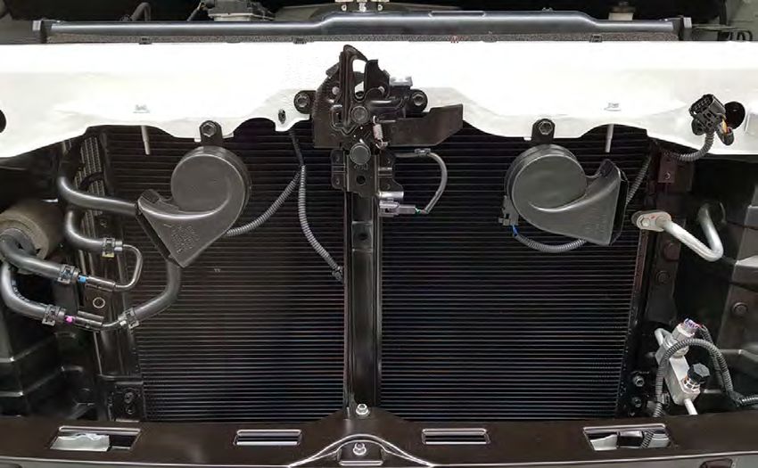
TOYOTA 3UR-FE SUPERCHARGER
    Installation Guide
  s) Connect the red (positive) wire directly to the positive battery terminal clamp.
  t) Connect the black (negative) wire directly to the negative battery terminal clamp.
  u) Run the fuse break-out lead to the inside of the fuse box directly behind the negative battery terminal,
     remove the IGN 10A (ignition) fuse and replace with the supplied fuse break-out.
  v) Replace the fuse box lid ensuring the intercooler pump loom is not pinched.
  w) Cable tie the loom to secure it where necessary.

                                                                    1u

  x) Connect the supplied ¾” x 1100mm long heater hose to the intercooler pump outlet, and run it up into the
     engine bay through the space at the top RHS of the intercooler radiator. The other end of this hose will be
     connected in step 8i.
  y) Connect the supplied ¾” x 850mm long heater hose to the intercooler radiator inlet (top), and run it up into
     the engine bay through the space at the top RHS of the intercooler radiator. The other end of these hoses
     will be connected at step 8j.

                     1y

                     1x

Page |9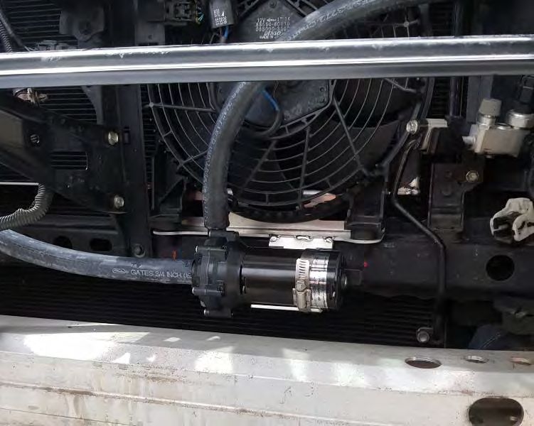
TOYOTA 3UR-FE SUPERCHARGER
      Installation Guide

2) Install Harrop intercooler radiator – LX570 AND LC200
   a) Remove the front Bumper-bar/Grille assembly.
   b) Un-clip the looms and remove 2x Horns.
   c) Dis-connect the Proximity sensor, Ambient air temp sensor and bonnet latch and remove the centre strut
      support along with Proximity sensor.
   d) Dis-connect the electric fan loom plug and remove the top M6 screw securing the fan to the front top panel.
   e) Tilt the fan forward and lift up and out of the vehicle.

                                                     2b

                                                                   1c

                                                                             2d

P a g e | 10
TOYOTA 3UR-FE SUPERCHARGER
Installation Guide
f) Assemble the Harrop Intercooler Radiator Top Brackets and Pump bracket
2f
2f
g) Temporarily remove the M6 screw that hold the A/C manifold block to allow some movement.
h) Install the Harrop Intercooler Radiator in front of the A/C condenser.
i) Secure the top 2x brackets with the original horn mounting screws.
j) The lower bracket will be secured in a later step (see step 1n).
2i
2g
k) Re-tighten the M6 screw that holds the A/C Fill block.
P a g e | 11TOYOTA 3UR-FE SUPERCHARGER
Installation Guide
l) Re-install the electric fan by inserting the rubber feet into the 2x holes in the lower bracket.
m) Use the supplied top adaptor bracket, spacer, M6 x 40 screw and M6 nut to secure the fan top mount.
2m
2l
n) Re-install the Centre strut and re-connect the Proximity sensor, Ambient air temp sensor and bonnet latch.
Secure the Intercooler Radiator lower bracket between the Centre strut and the cross-member using the
original screw.
o) Re-install the horns one at a time to the original position.
p) Re-connect all loom plugs.
q) Install the Intercooler Pump on the bracket provided and secure with 2x hose clamps. Orient the pump with
the outlet pointing slightly forward of vertical to allow the hose to pass in front of the electric fan.
2n
2q
P a g e | 12TOYOTA 3UR-FE SUPERCHARGER
Installation Guide
r) Connect the ¾”x 500mm long pump inlet hose between the pump inlet and the Intercooler Radiator RHS
pipe. Secure with hose clamps.
s) Connect and run the ¾” x 1300mm long pump outlet hose under the LH A/C Condenser pipe and through the
gap in into the engine bay. Secure the pump outlet with a hose clamp. The other end of this hose will be
connected in step 8i.
2r
2s
t) Connect the ¾” x 1500 long Radiator inlet hose to the lower LHS of the Intercooler radiator and run through
the gap behind the A/C Fill block and into the engine bay. Secure the Radiator inlet with a hose clamp. The
other end of this hose will be connected in step 8j.
2t
P a g e | 13TOYOTA 3UR-FE SUPERCHARGER
Installation Guide
u) Using the supplied cable ties, ensure the Intercooler hoses are secure and cannot come into contact with the
supercharger drive belt.
v) Connect the supplied intercooler pump loom to the pump and run the loom along the lateral chassis
member and cable tie it as necessary to secure it. Allow some slack in the loom near the pump plug to
enable easier disconnection if required.
w) On the LHS of the intercooler radiator, there is enough space to pass the loom through the LH infill panel
without cutting it. Route the loom toward the fuse box, located behind the battery.
x) Remove the fuse box lid.
P a g e | 14TOYOTA 3UR-FE SUPERCHARGER
Installation Guide
y) The intercooler pump loom relay is mounted on the outside of the fuse box, as shown in the image below.
Position the relay and mark the centre of the mounting hole. Drill a Ø5.5-6.0mm hole and secure the relay
using the supplied M5 x16 Button head screw and nut. Make sure the relay is mounted low enough so the
fuse box lid can still close.
1y
z) Connect the red (positive) wire directly to the positive battery terminal clamp.
aa) Connect the black (negative) wire directly to the negative battery terminal clamp.
bb) Run the fuse break-out lead to the inside of the fuse box directly behind the negative battery terminal,
remove the ENG-IG NO.1 10A (ignition) fuse and replace with the supplied fuse break-out.
cc) Replace the fuse box lid ensuring the intercooler pump loom is not pinched.
dd) Cable tie the loom to secure it where necessary.
1bb
P a g e | 15TOYOTA 3UR-FE SUPERCHARGER
Installation Guide
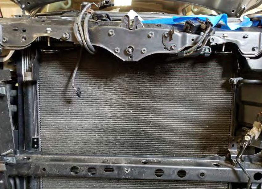
3) Removal of Toyota Intake Manifold
a) Remove plastic engine cover
Dis-connect/unplug the following wiring:
b) ETC (throttle body)
c) Coolant temperature sensor (coolant cross-over pipe beside top radiator hose on engine front)
d) ACIS VSV (LHS of OE manifold, behind the fuel purge valve). Wrap the plug with insulation tape to seal it.
The solenoid does not need to be removed as it does not get re-used.
3d
3c
3b
P a g e | 16TOYOTA 3UR-FE SUPERCHARGER
Installation Guide
Dis-connect the following components:
e) Fuel pressure regulator reference and crankcase ventilation tubes from the Throttle intake tube. Remove
the Throttle tube with resonance chamber. These are not re-used.
3e
f) Crankcase ventilation hoses from LH and RH rocker covers. Un-screw the clip and tee-piece from the
manifold, and completely remove them from the engine. Only the T-piece will be re-used.
g) Fuel purge valve from the manifold LHS.
h) Fuel purge valve hose from the throttle end of the manifold.
i) PCV valve hose from the front of the manifold. This will be reconnected in 10d.
j) Brake booster hose at the rear LHS of the engine, if equipped.
k) Remove the Radiator top hose completely. This will be re-connected at step 10i.
l) Dis-connect the coolant hoses from under the throttle body (not visible in image). These will be re-
connected in step 10e and 10f.
m) Wiring loom bracket from the RHS rear of the manifold.
P a g e | 17TOYOTA 3UR-FE SUPERCHARGER
Installation Guide
3J
3m
3f 3g
3f
3f
3f
3i
3h 3k
n) Remove the OE intake manifold, discarding the foam inserts at either side.
i) It is necessary to un-clip the wiring loom at the rear of the manifold before it can be removed.
ii) Remove the 2x wiring loom clips from the back of the OE manifold. These will be re-used.
iii) Apply suitable tape over cylinder head ports to prevent foreign material from entering.
o) Remove the 2x foam insulation from the engine valley.
3n ii)
P a g e | 18TOYOTA 3UR-FE SUPERCHARGER
Installation Guide
4) Removal of Toyota Coolant crossover pipe
Dis-connect the following components:
a) Heated PCV hose to Coolant cross-over pipe.
b) Heated PCV to throttle body coolant hose. Unscrew the bracket under the crossover pipe and remove
completely. This will not be re-used, but replaced with 5/16” x 650mm hose in step 6f.
c) Heater hose to Coolant cross-over pipe.
d) Thermostat housing to Coolant cross-over pipe.
e) Oil coolant line bracket adjacent to the radiator hose connection.
Heated PCV valve
4a
4b
4c
4d 4e
f) Remove the Toyota Coolant cross-over pipe from the engine. The gaskets and nuts will be re-used.
g) Remove the coolant temperature sensor from the Toyota Coolant cross-over pipe. This will be re-used.
P a g e | 19TOYOTA 3UR-FE SUPERCHARGER
Installation Guide
5) Removal of Toyota Oil Coolant lines
The Toyota Stainless Steel coolant lines on the front of the engine are removed and replaced with Harrop
Stainless Steel coolant lines to create clearance for the supercharger belt.
Disconnect or remove the following components:
a) Toyota FEAD belt. Turn the tensioner anti-clockwise with a 14mm socket until there is enough slack to
remove the belt.
b) Toyota Oil coolant line hoses from the thermostat housing and valley. Leave the hoses connected to the
engine and disconnect the pipe end only. These are re-connected to the Harrop oil cooler pipes in step
6h.
5b
5b
c) Remove the Toyota elbow hoses at the oil cooler under the LH front of the vehicle.
P a g e | 20TOYOTA 3UR-FE SUPERCHARGER
Installation Guide
d) To enable removal of the Toyota Oil Coolant lines, the AC compressor needs to be shifted away from the
engine. Remove the 2x bolts and 2x nuts that secure the AC compressor to the engine. These are accessible
from inside the LH front wheel arch. Remove the road wheel and flexible covering inside the wheel arch to
gain access.
5d
5d
e) Slide the AC compressor away from the engine approximately 25mm (1.0”). It is not necessary to
remove the AC compressor completely, disconnect any AC system hoses or de-gas the AC system.
f) Remove 1x mounting screw on the front LHS Timing cover, and 1x mounting screw on the side of the
engine block behind the AC compressor and remove the Toyota Oil Coolant lines.
P a g e | 21TOYOTA 3UR-FE SUPERCHARGER
Installation Guide
6) Installation of Harrop Engine Coolant cross-over Pipe
a) Install the Coolant temperature sensor (removed in a previous step) to the Harrop cross-over pipe. Re-
use the Copper washer and suitable sealant on the threads of the sensor.
6a
b) Using a suitable sealant, install the cross-over pipe to the engine re-using the original gaskets and nuts.
c) Install the supplied 1/2” x 190mm long heater hose between the Ø14mm barb on the crossover pipe and
the thermostat housing.
d) Reconnect the original heater hose to the Ø17mm barb on the RHS of the crossover pipe.
e) Reconnect the original heated PCV hose to the Ø10mm barb on the rear of the crossover pipe.
f) Connect one end of the supplied 5/16” x 650mm hose to the heated PCV valve and route under the
crossover pipe toward the RHS of the vehicle. This hose replaces the OE hose removed in step 4b.
g) Secure all connections with original hose clips.
h) Position the coolant hose which was dis-connected in step 5b from the Toyota oil cooler pipes, over the
engine coolant crossover pipe. This will be connected in step 9b.
6f
6e 6h
6d
6c
P a g e | 22TOYOTA 3UR-FE SUPERCHARGER
Installation Guide
7) Installation of the Supercharger idler bracket
a) Remove the 3x bolts shown below.
7a
b) Install the Harrop supercharger idler bracket using the supplied bolts.
7b
P a g e | 23TOYOTA 3UR-FE SUPERCHARGER
Installation Guide
8) Installation of the Harrop Supercharger
a) Install the original harness clips removed in a previous step to the rear of the supercharger manifold.
8a
b) Remove the masking tape from the inlet ports and ensure the head faces are clean, dry and free from
foreign material.
c) Double check that the 8x manifold face O-rings are all in place.
d) Lower the Supercharger/manifold assembly into position. This is a heavy lift – utilise a suitable hoist.
e) Tighten down the manifold using the 2x original nuts on the front studs, and the 8x supplied screws.
f) Install the supplied Supercharger belt to the original FEAD, but route the belt over the supercharger
pulley according to the following diagram:
Harrop Supercharger
Drive Pulley
Harrop Crossover Pipe
Idler Pulley
Harrop Idler Pulley
P a g e | 24TOYOTA 3UR-FE SUPERCHARGER
Installation Guide
g) Re-tighten the fuel-rail bolts that were left loose in a previous step.
h) Install the original throttle to the supercharger inlet using the original screws. The electrical connector
should be at the top and horizontal. Ensure the supplied O-ring is in position. Torque screws to 10-
12Nm.
8h
i) Connect the free end of the hose that is connected to the intercooler pump outlet to the Y-piece
towards the rear RHS of the supercharger manifold. This hose is 1100mm long for Tundra, refer to step
1x. For LC200 and Lexus570, this hose is 1300mm long, refer to step 2s. Secure with a hose clamp.
j) Connect the free end of the hose that is connected to the intercooler radiator inlet (top) to the Reservoir
outlet on the RHS of the supercharger. This hose is 850 long for Tundra, refer to step 1y. For LC200 and
Lexus570, this hose is 1500mm long, refer to step 2t. Secure with a hose clamp.
8j
8i
P a g e | 25TOYOTA 3UR-FE SUPERCHARGER
Installation Guide
9) Install Harrop Oil coolant pipe
a) Position the supplied oil cooler pipe between the engine fan and the Harrop idler pulley. Refer to the
image below for the correct orientation. The pipes are shown in red.
b) This step connects the Harrop oil cooler pipe to the original coolant hoses, dis-connected in step 5b.
The first hose is above the water-pump pulley. Position the hose installed in step 6h over the engine
coolant crossover, and connect it to the oil cooler pipe. Secure with hose clamps.
c) Secure the pipe to the front of the LH timing cover with the supplied M6 x 16 screw.
9b
9b
9c
d) From underneath the front LHS of the vehicle, install the supplied 90° oil cooler hose bends, noting the
orientation
i) The larger Ø end of each bend fits on the Harrop oil cooler pipe. Secure with the supplied hose
clamps.
ii) The smaller Ø end of each bend fits on the Oil cooler. Secure with the original hose clamps.
9d i)
9d ii)
P a g e | 26TOYOTA 3UR-FE SUPERCHARGER
Installation Guide
10) Install Ancillary hoses and brackets
a) Tundra: On the LHS of the supercharger, connect the supplied 11/32” x 600mm long vacuum hose to the
top Ø9.5 elbow. Connect the other end of this hose to the brake booster hose barb.
Lexus 570 and Landcruiser 200: Install the supplied blanking plug to the top Ø9.5 elbow on the LHS of
the supercharger.
b) Connect the fuel purge hose that was disconnected in step 3h to the lower Ø8.0mm elbow.
c) Using the supplied M6 x 16 screw, mount the fuel purge valve to the tapped hole half way along the
manifold using the original mounting bracket.
d) Re-connect the PCV hose to the Ø10 hose barb under the supercharger inlet cover.
e) Connect the original Throttle body coolant hose to the horizontal hose tail on the Throttle body.
f) Connect the supplied 5/16” x 650mm coolant hose (already connected to the heated PVC in the valley in
step 6f) to the vertical hose tail on the Throttle body.
g) Use the supplied Air vent pipe bracket to re-position the vent pipes and loom toward the RHS of the
vehicle approximately 20.0mm. Use the original screw to secure the supplied bracket to the front of the
engine. Use the supplied screw and nut to re-fit the original pipe bracket to the supplied bracket.
10a
a
10a
10e a
a 10f
a 10c
10b a
10g a
a 10d
a
h) Secure all hose connections with the original clamps.
i) Re-connect the top radiator hose that was removed in step 3k in the original orientation and secure with
the original clamps.
j) The OEM Airbox is utilised unmodified, including the Hydrocarbon trap. Temporarily un-clip the air-box
lid and install the Harrop intake boot between the original air-box and the throttle body. Re-use the
hose clamps from the Toyota intake boot. The hose barbs should point to the rear of the vehicle, with
the larger one closer to the Air-box. Re-clip the air-box lid into place.
P a g e | 27TOYOTA 3UR-FE SUPERCHARGER
Installation Guide
10l
10k
10m
k) Screw the OEM crankcase ventilation T-piece to the rear RHS of the Supercharger manifold, using the
spacer and screw provided. Refer to step 3.f.
l) Attach one end of the supplied 430mm long ½” vacuum hose to the centre branch of the T-piece, and
the other end to the Intake boot.
m) Attach one end of the supplied 480mm long ½” vacuum hose to the RH facing branch of the T-piece, and
the other end to the RH Rocker cover.
10n
n) Using the remaining 750mm long ½” vacuum hose, connect between the LH facing branch of the T-piece
and the LH Rocker cover.
o) Swap the fuel pressure regulator with the supplied regulator, Harrop #99-REG14917. Connect one end
of the supplied Ø4.0mm x 750mm long hose to the Vacuum tail of the regulator.
10o
10p
p) Connect the other end of the Ø4.0mm hose to the barb fitting on the LHS of the supercharger manifold,
adjacent to the fuel purge valve.
P a g e | 28TOYOTA 3UR-FE SUPERCHARGER
Installation Guide
11) Install wiring patch looms
a) Install the supplied MAF – IAT break-out loom. Refer to the image below. Connect the female MAF sensor
plug (shown in BLUE) on the supplied loom to the OE MAF sensor on the air-box. Connect the male MAF
sensor plug (shown in RED) to the OE loom plug.
b) Connect the IAT plug (shown in PURPLE) to the IAT sensor approximately half way along the RH side of the
supercharger manifold. Note this plug may look different to the image.
c) Connect the supplied throttle extension loom between the original throttle connector and the throttle body.
11b
11a
11c
11c
P a g e | 29TOYOTA 3UR-FE SUPERCHARGER
Installation Guide
12) Install high flow fuel pump
a) Ensure the fuel tank is nearly empty before completing the following steps.
b) Raise the vehicle on a suitable hoist according to the vehicle owner’s manual.
c) Dis-connect the fuel delivery and return lines from the front top of the tank.
d) Dis-connect the fuel filler tube at the rear top of the fuel tank.
e) Dis-connect the fuel purge vent tube from the canister mounted above the fuel tank, and the wiring loom
clip from the top of the tank.
12c
12d
12e
f) Dis-connect the fuel vent line at the filler neck.
12f
P a g e | 30TOYOTA 3UR-FE SUPERCHARGER
Installation Guide
g) Un-plug the wiring to the fuel pump at the top of the fuel tank.
12g
h) Support the fuel tank with a transmission stand in the centre.
i) Un-screw 3x M8 bolts (14mm head) and remove 3x pins/wire clips to remove the 3x fuel tank support straps.
12i 12i
j) Slowly lower the fuel tank, ensuring that all components are dis-connected and place on a work bench.
k) Clean the top of the tank, especially around the white fuel pump module.
P a g e | 31TOYOTA 3UR-FE SUPERCHARGER
Installation Guide
l) Remove the 2x retaining clips from the fuel lines on top of the fuel pump module, and withdraw the lines.
m) Using a suitable tool, us-screw the pump module retaining ring (CCW). It will be necessary to depress the 3x
locking barbs one at a time as the ring is rotated.
12m 12o
12m
12l
12n
12m
n) Remove the fuel pump module from the tank, allowing time for any fuel to drain out in the process.
o) Dis-connect the two wiring plugs underneath the top of the module. Unplug the pump power loom from the
pump and set aside.
p) Use a sharp pick or small screwdriver to un-clip and separate the two halves of the module.
q) Un-clip the 2x tabs that hook over the side of the lower half of the module, and remove the pump housing.
r) Un-clip the 5x pick-up filter tabs and remove the filter, then withdraw the fuel pump.
12p
12r
12q
P a g e | 32TOYOTA 3UR-FE SUPERCHARGER
Installation Guide
s) Remove and discard the old fuel filter and swap the O-ring spacer to the new supplied fuel pump.
t) Fit the new supplied fuel filter to the new pump.
12s
12t
12s
u) Inspect the O-ring in the fuel pump housing. Replace with a new supplied O-ring of the same dimensions if it
is worn or damaged.
12u
12v
v) Re-install the new pump/filter to the housing making sure that the pump outlet is firmly seated in the O-ring.
Push the 5x clips on the filter all the way home and ensure each clip is secured.
w) Install the pump housing to the lower module half making sure that the 2x tabs that hook over the side of
the lower half of the module are engaged and secure. Refer to step 13q.
x) Plug in the pump power loom to the pump.
y) Assemble the two halves of the pump module and engage the 3x retaining clips. Refer to step 13p.
z) Re-connect the fuel level sender loom to underneath the top of the module.
aa) Re-install the fuel pump module to the tank, and the tank to the vehicle reversing the steps that were used
to remove them.
P a g e | 33TOYOTA 3UR-FE SUPERCHARGER
Installation Guide
13) Finalise installation
a) Re-fill the engine radiator with Genuine Toyota coolant, according to the vehicle owner’s manual.
b) Initial Intercooler system fill. Coolant to be used is either Ford WSS-M97B44-D and/or GMW3420, mixed
with distilled or deionised water in a 50% concentrate. Note filling with a con-compliant coolant will void
warranty. Fill via the intercooler reservoir, allowing time for the coolant to fill down to the front mount
radiator. The ideal level is 25mm below the top of the reservoir with the cap removed. Use the bleed screw
on the intercooler radiator to allow air to escape during filling.
13b
c) Re-fit front Grille.
d) Re-fit under tray.
e) Re-fuel the vehicle with 91-AKI (93-RON) minimum fuel.
f) Reconnect battery.
g) Turn the ignition on without starting the engine. The intercooler pump should be running. Allow 1-2
minutes for coolant to circulate and switch the ignition off. Re-bleed the intercooler radiator and top-up the
coolant level.
Intercooler Coolant circuit
P a g e | 34TOYOTA 3UR-FE SUPERCHARGER
Installation Guide
h) CARB/EO sticker. Clean a flat, visible surface under the hood and affix the enclosed CARB EO sticker which
applies to this kit, indicating that this kit is emissions legal in North America.
i) Affix the supplied fuel specification label to the inside of the fuel filler flap over the existing OEM
fuel label. This label is to ensure the vehicle is filled with minimum 91-AKI (93-RON) and not E85 fuel.
14) Initial engine start
Minimum 91-AKI (93-RON) fuel must be used. E85 fuel is not to be used.
It is the installer’s responsibility to ensure all coolant connections are leak free, all electrical connections are
sound and proper procedures have been followed during installation.
a) Start the engine and allow to idle only. Check that the supercharger belt is running smoothly and is correctly
aligned on all pulleys.
b) Ensure that wiring looms, hoses or similar cannot come into contact with the Supercharger belt.
c) Allow the engine to reach normal operating temperature, then switch off the engine and allow to cool. Re-
check the Intercooler reservoir level and the engine radiator level. Check for any leaks.
P a g e | 35You can also read