BMW E36 M3 Twin Screw Supercharger Kit Level I and II Installation OBDI TS level II installed shown below
←
→
Page content transcription
If your browser does not render page correctly, please read the page content below
BMW E36 M3

    Twin Screw Supercharger Kit
      Level I and II Installation

OBDI TS level II installed shown below

                  1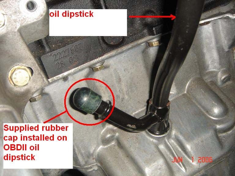
OBDI level II installed shown below

Thank you for purchasing the Active Autowerke twin screw supercharger system,
it has been designed and thoroughly tested for maximum performance and
reliability.

Please read the instructions thoroughly before attempting the disassembly and
assembly of this system. If you feel that you are not capable of doing this job
please find a qualified technician of at least a “B status” to do the job.

No special tools are required to do this installation, basic hand tools are the only
tools required.

We recommend a fresh set of stock spark plugs before installation of the
supercharger and fresh oil in the motor

Suggested fuel octane at a minimum is 91 based on USA R+M/2 method, if 93 or
94 is available then use it.

The system is warranted against any defects in any components for 1 year
with unlimited mileage. The warranty does not cover any incidental
damages or labor to remove and replace any components

                                          2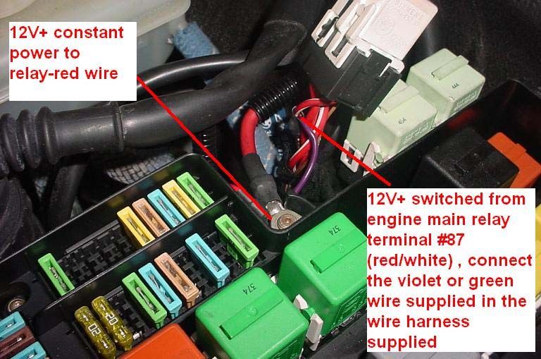
Suggested time for total installation of this system:
Level I = 10-12 hours
Level II = 16-18 hours

Suggested service :
1) Engine oil and filter every 5,000 miles at maximum , we recommend a good
   quality synthetic motor oil of at least a 5W30, 10W30, or 15 W50 weight
   depending on your geographic location and time of the year
2) Spark plugs at least every 15,000 miles

3) Air filter K+N, RU 3130 every 6 months, if dusty conditions, please use
discretion for more frequent service interval.

4) Supercharger oil change every 20,000 miles, oil = 15W50 or 20W50
synthetic motor oil. Fill is exactly 4 oz.

Table of contents

Car prep _______________________________4
Front bumper disassembly________________20
Misc. body prep________________________ 22
Component installation___________________26
Prep of engine wiring harness & vanos oil line
adjustment_____________________________35
Belt routing_____________________________41
Hose routing and coolant flow______________42
Electrical wiring level2 systems_____________43
Vacuum hose diagrams________________45-46
Inlet pipes and hoses_____________________47
HFM connections________________________51
Filling oil in sc___________________________53
Filling and bleeding aftercooler______________54
Bypass valve installation___________________57
Road testing_____________________________58

                                       3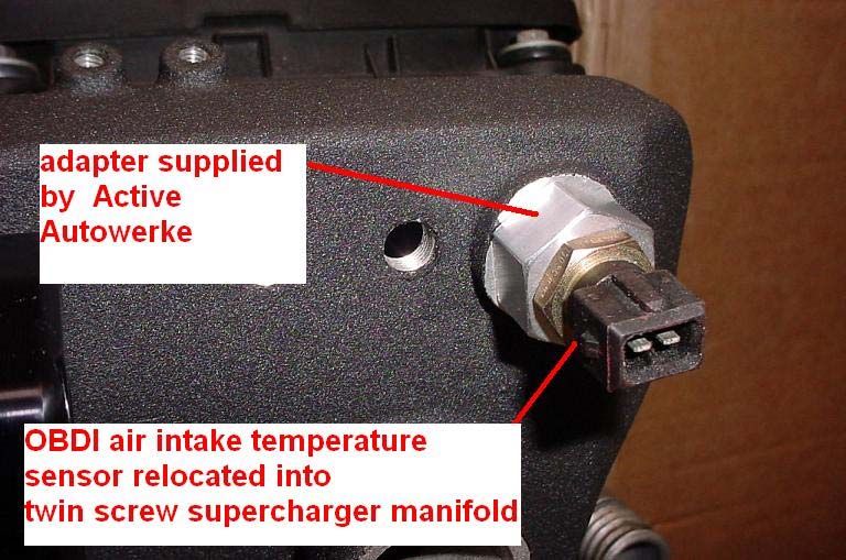
Car Preparation and relocation of a few items
Engine compartment disassembly:

  1. Locate the battery in the trunk on the right side. Disconnect the battery
     negative terminal.

  2. Remove DME –

 OBD II vehicles

  Ship to Active for Programming ( applicable only to OBDII equipped vehicles).
  An ECU form has been provided for this, if you did not get one, you can go to
  the website www.activeautowerke.com and download one from the “tech
  center” section, please fill it out and attach it to the DME.

  - For OBD I vehicles, a new E-prom has been provided for you to install        .

  DME removal 1

                                       4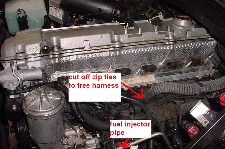
DME removal 2

                             Remove Screws

OBDI DME (BOSCH) ECU part number:

0-261-200-413 325i 10/92-11/95
0-261-203-506 M3 03/94 – 12/94
0-261-200-413 M3 01/95-11/95

OBDII (SIEMENS) has several part numbers.

328i 5WK90351
328i 5WK90355

M3 5WK90172
M3 5WK90354

                                 5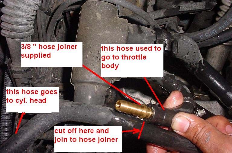
DME removed with wire harness attached

   Removal and modifications of throttle body :

3. Remove air filter box, HFM, throttle body hose. Note: The HFM, HFM air box
and HFM booth will not be reused. A new HFM has been provided.

    On OBDII vehicles, remove bolts for ASC throttle body, disconnect connector
for ASC throttle body, disconnect actuator cable and remove ASC throttle body
(OBDII only). The cable must remain intact in the vehicle, it will not be
reconnected, tuck it away under the existing hardware,

    On OBDI vehicles, remove the throttle body put it aside and save existing
bolts, they will be reused. Note: the water cooling hoses and the purge valve
hose must be removed as well in this step.

On OBDII vehicles, remove the throttle body put it aside, the bolts for the throttle
body will not be reused. New studs have been provided.

   On OBDI and OBDII vehicles the throttle cables must be removed, a new
cable has been provided.

4. Remove alternator cooling duct, it will not be reused.

                                          6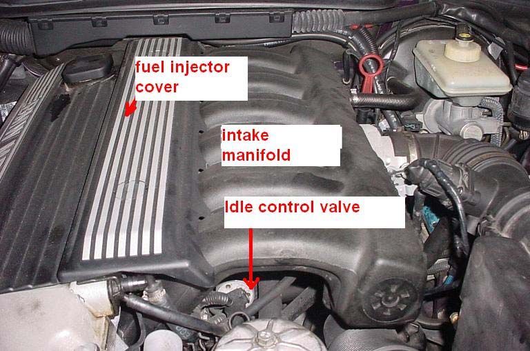
OBDI engine bay shown below

Alternator cooling duct removal

                             REMOVE
                                          REMOVE HOSE
                                          Clamp down
                                          here

                                      7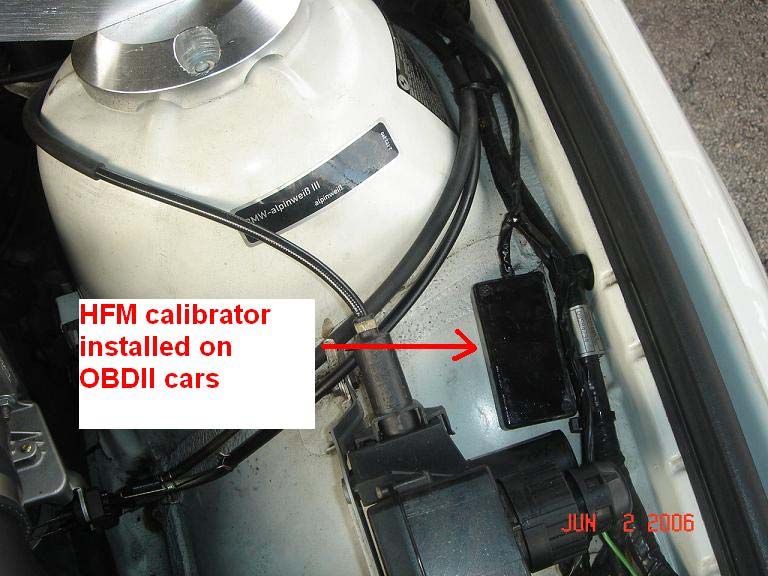
5.    OBDI and OBDII vehicles, remove idle control valve electrical connector
and remove the valve with hoses. The valve will be reused but the hoses will not.

6A. OBDI 1995
OBDI vehicles only: Remove the charcoal canister and relocate to passenger
side of engine bay using the supplied hoses and bracket

Charcoal canister re-location

Relocate charcoal canister from location A to location B
with bracket and hoses provided

                                        8
Remove small vacuum hose from canister and unclip larger hose

Cut off connector from larger hose

Connect hoses provided and route along the rear of the engine to new location B

Mount the new bracket supplied to canister and mount as shown below in location B

                                       9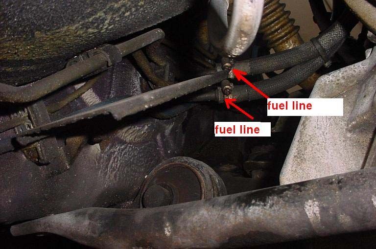
10
6.   Drain coolant enough to allow removal of upper radiator hose, remove hose

Save hose clamps from the hose, the hose will not be reused, a new hose has
been provided.

7. Disconnect cruise control cable from throttle body. It will be reconnected later
.Disconnect the throttle cable. Disconnect coolant hoses from the throttle body.
The coolant hoses will not be reconnected, they will by pass the throttle body.

On OBDII throttle body, locate the 2 water cooling fittings ( brass looking fittings
and cut them off flush where they meet the aluminum housing of the throttle
body, this is necessary for proper clearance.

ON OBDI vehicles, there are 2 rubber caps provided to cap off the 2 water
cooling hose connections and one small rubber cap to block off the purge valve
hose connector. Note: the purge valve hose will be connected later in the back of
the supercharger inlet housing.

                                         11
8. Remove fuel rail cover by carefully prying the bolt covers with a thin
screwdriver, remove the attachment bolts (10mm head) and extract the rail cover
9. Remove the 2 hold down bolts for the fuel rail (10mm head) and lift the fuel
rail straight up (relative to the direction of the injectors)
10. Remove the cable assembly from the fuel injectors and set over the top of
the engine/valve cover.
11. Set the fuel rail out of the way. On OBDII vehicles It is not necessary to
disconnect the fuel lines. The fuel lines will be reused.
On OBDI vehicles the fuel lines to the fuel rail will not be reused, new lines are
provided. Remove all lines in engine bay all the way down to the hard metal lines
at the frame rails. On early 95 M3 cars the fuel filter is attached to the engine
block, on these vehicles, we recommend to remove the fuel line down to the top
of the filter. On 95cars new fuel lines are provided with new hose clamps.
1212. OBDI only. Remove fuel lines from underneath car at frame rail, they
will not be reused, new fuel lines are provided.
13. Remove intake manifold support brackets from the manifold and the
engine block/engine mount, they will not be reused.
1314. Disconnect vacuum lines from under intake manifold, these vacuum
lines will be reused on the new intake manifold and the supercharger inlet
housing ( a vacuum line drawing is provided in these instructions)
15. Disconnect IAT (intake air temperature) sensor electrical connector
from the intake manifold.
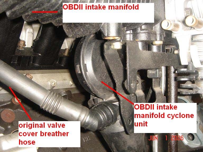
16. On OBDII vehicles disassemble cyclone separator and other items
under intake manifold. Disconnect crankcase vent line from valve cover.
The cyclone separator and valve cover hose will not be reused. A new valve
cover breather hose is provided.
14IAT Sensor Cyclone
Breather Hose
OBD II Valve Cover
Breather Hose Assembly
15OBD II Valve Cover
Breather Hose Assembly
INSTALLED
17. On OBDI vehicles, the valve cover breather hose connector that used to
go to the intake manifold (small vacuum hose fitting) must be blocked off. A small
vacuum plug/cap is supplied for this.
On OBDI vehicles, the valve cover breather hose will be reused.
18. Remove intake manifold mount nuts (7 X 11 mm head nuts)
19. Pull the manifold off the engine and set aside, the intake manifold will
16not be re-used, a new one is provided.
20. OBDII vehicles, remove oil drain hose from the cyclone separator to oil
dipstick, install the rubber cap provided on to the dip-stick. See picture below.
OBDII vehicles only: At this time install the supplied dipstick support bracket.
See picture below.
1721. Release belt tension on AC belt and remove belt, put aside for
reinstallation later.
22. Release tension from main drive belt and remove belt, the stock belt will
not be reused, a new one has been provided. Please take note of the new belt
size and put aside . You will need the size for reference later when it come times
for a replacement.
23. Remove the main belt tensioner from the front of engine, a new one has
been provided with new bolts. Now is a good time to install the new main belt
tensioner supplied, torque the bolts supplied to 18 ft-lbs.
1824. Remove 2 alternator mount bolts, do not remove alternator, new bolts
have been provided to remount the alternator along with the new supercharger
bracket.
Alternator Mounting bolt
19Front bumper disassembly:
25. Pry out trim sections from front bumper
26. Remove fasteners from under tray and “pork chop” trim sections. The
plastic under tray must be removed as well.
That is if it is still there, by now most of them have broken off or fallen off from
age. It will not be reused, if you choose to reuse it you may have to trim small
sections of it as needed for clearance
2027. Reach up to side of left side brake duct and disconnect air temp sensor
from brake duct.
28. Remove connectors from fog lights
29. Remove 4 primary bumper mount bolts – remove bumper by pulling
straight forward and set in a safe place
Remove 13mm Head Nut.
2 on Driver’s Side
2 on Passenger Side
21Miscellaneous body preparation:
Inside of cabin area:
30. Remove stock throttle cable.
First you must remove the under dash trim panel. Remove the 2 upper screws,
and 1 screw underneath. CAREFULLY pull the panel backwards until the tab
comes free from the center console. Disconnect the electrical connections and
set the panel aside
Disconnect the end of the throttle cable from the throttle pedal. Using a very
long, skinny screwdriver, press against the underside of the plastic clip for the
cable. Give a sharp blow to the end of the screwdriver to pop the lower end of
the clip free. A lighter pry on the upper side of the clip should release it. Pull the
cable out from up in the engine bay.
2231. Modify alternator cooling duct as shown (this is optional, we
recommend it for a nicer cleaner looking installation). Also another option is
to purchase the European spec radiator support cover which has a very clean
look.
23Modified Cover OPTIONAL
32. Remove the driver’s side corner lamp by prying gently on the release tab
that holds the lamp. See picture below.
24Remove driver’s side head lamp as shown below
33. Remove horn from horn bracket (location A) and cut bracket from under
left side headlight. Using a small hammer, tap the remaining pieces flush.
Relocate and Mount horn to bumper mounting (location B) as shown
25Component installation:
Throttle cable installation on to the chassis:
34. Install the new throttle cable, apply force until the cable clip is secured
by “snapping” into place. Confirm the installation by tugging on the cable.
35. Connect the end of the throttle cable to the throttle pedal
2636. Reinstall the interior trim panel – don’t forget to reconnect the
light and buzzer connectors
27Level 2 ONLY…
Mounting of intercooler pump heat exchanger and pump:
37. Mount intercooler pump bracket as shown,
On the 4 doors vehicles, there is a small hole just below the metal inner fender
where the inner plastic wheel housing is attached, this hole is left blank and is
easily visible.
On the 2 door vehicles, a sheet metal bolt that holds the inner fender wheel
house has to be removed and the supplied bolt with nut is used to attach the
pump ( see picture below for a better view of this bolt location)
2838. Mount intercooler pump in bracket with proper orientation as shown
39. Mount intercooler heat exchanger to outboard bumper strut mounts by
removing nuts from studs, mounting supplied bracket to studs and heat
exchanger
2940. Connect hose provided from the pump outlet to the heat exchanger inlet.
41. Locate the after-cooler reservoir / tank and mount it on the base behind
the passenger side shock tower, a 6 mm threaded hole is provided by BMW and
is not used, use the bolt provided and bolt the tank to the base.
3042. Locate ¾” coolant hose that runs from tank to pump. Hose #1
Hoses are marked for your convenience and pre cut to proper length. Route as
shown. Install with hose clamps. Tighten clamp on fill tank.
NOTE: we have cut the hose from the tank to the pump inlet a bit longer for those
of you who have installed euro style headlamps, if you do not have euro style
headlamps you can cut the hose to proper length.
Picture below shows euro style headlamp with suggested hose routing.
31Preparing of engine wiring harness, vanos oil line adjustment,
installing new fuel lines and modification of existing coolant
throttle body water hoses :
43. On OBDI vehicles: Take a pair of dykes and cut the tie straps that hold the
engine harness to the engine bracket that it is attached to, this is needed to free
up the wires for :
A) the throttle position sensor connector
B) the air temperature sensor
C) the idle control valve
Note: on 95 (OBDI vehicles) there is a small 3 wire harness provided to extend
the connector for the throttle position sensor. Use the time now to cut the throttle
position sensor wire and extend it with the wires provided.
It is very important that the above wires have enough length to reach the
sensors otherwise the entire supercharger assembly has to be removed to
correct this!
3244. OBDII vehicles, the bracket that holds all the wiring harness to the
engine block has to be removed and the harness left loose for the sensor wires
to have extended lengths, secure the other wires that are not pertinent for the :
1) Throttle position sensor
2) The air temperature sensor
3) The idle control valve
Take the coolant hose that used to go to the throttle body and route it so that it
goes straight to the cylinder head connection. You have just by-passed the
throttle body heating. There is no provision to heat the throttle body with the twin
screw sc system, but this is not a problem.
See picture below:
Throttle body hoses modified
OBD II only.
33OBDI vehicles, the coolant hose that used to go to the throttle body is now
connected to the hose that used to go to heater in the air box. Cut as
shown below in the picture and connect with the brass 3/8” connector
provided by Active Autowerke.
Take the vanos oil line and loosen the banjo bolt at the oil filter housing, use the
supplied jig and align the hose as shown below. Tighten the banjo bolt securely
after adjusting.
3445. OBDI only: Locate the fuel lines supplied and install them , the longer
line (supply)goes to the front of the engine , route it so that it comes up behind
the oil filter housing, make sure it does not interfere with the steering shaft or
other moving parts, route the other line (return) to the rear of the engine. These
lines will be connected after the fuel injectors and fuel rail are installed
35Installing the main supercharger / intake manifold system:
46. Take the main assembly and slowly lower it on to the engine cylinder
head while aligning the intake manifold studs onto the intake manifold. Support
the manifold while catching the 7 X 11 mm head nuts, run the nuts down but do
not tighten them. Leave them loose so that the intake manifold/supercharger
assembly can move up and down for later alignment of the supercharger snout
bracket to the engine.
47. At this time double check the wires for the air temp sensor, Throttle
position and idle control valve are ok and length is good.
48. Take the snout bracket and slide it over the snout of the supercharger
drive while aligning it to the 2 mounting holes. Insert the bolt with the idler pulley
and spacers, run the bolt down until snug, also install the counter sunk bolt in the
bottom hole of the bracket until flush. Now tighten the intake manifold nuts to
approximately 13 ft-lbs. If you cannot get a torque wrench on them, use your
discretion.
49. Now torque the snout bracket bolts, the upper bolt to approximately 35-
37 ft-lbs, tighten the lower one until the head of the allen key feels like it will start
stripping (it is difficult to properly torque this bolt with such a small head).
Note: some alternators have no threads on the back side so a 10 mm nut
will have to be used to secure the bolt.
Note: We recommend to apply “anti seize “ on these
bolts so that they can be removed for any service
work later on.
36Tighten the pinch bolt on the top side of the snout bracket, it is a 6 mm hex bolt
with a 5 mm head, approximate torque is 8 ft-lbs.
3750. Locate the new supplied fuel injectors and install them now. Install the
wiring harness onto the fuel injectors.
On the OBDI vehicles install the new fuel lines to the fuel rail.
51. Install the supercharger drive pulley on to the shaft and hand tighten the
bolt ( 10 mm allen ).
38For illustrative purposes a line drawing below shows the snout bracket with
applicable fasteners:
52. Install the adjustable idler pulley with bolt and nut provided. The pulley
may have been pre-installed on to the bracket when shipped to you. Snug the
bolt down making sure that the pulley can slide in the slot.
3953. Install the new main drive belt supplied routing it as shown in the
diagram below.
Adjust the “adjustable idler pulley “in the slot for maximum contact around
alternator pulley and tighten the bolt. At the same time it is important to check the
main tensioner for adequate travel,
if the tensioner does not have enough travel it will not absorb or take up enough
slack when loading on the belt occurs. We recommend at least 1” of travel on the
tensioner pulley.
At this time tighten the supercharger belt as much as you can, it is a bit difficult
because it is not easy to hold the supercharger from turning. We recommend
taking a socket wrench and just hold it in place and then hit it with you hand.
Do not be concerned about tightening the bolt, when the engine starts the bolt
will tighten automatically.
Install the A/C belt
40At this time you can install the engine fan clutch along with the fan
Install the new upper radiator hose as well, fill the cooling system and leave open
the bleed screw.
41Level II 1995…
Installing the rest of the after-cooler/intercooler water hoses
from the heat exchanger to the intake manifold:
54. Locate the hose supplied that goes from the heat exchanger to the
intake manifold lower inlet fitting and route it along the frame up into the engine
bay so that the hose has a smooth route, be careful not to kink it. This is hose #3
55. Locate the hose supplied that goes from the intake manifold to the
reservoir and mount it as shown in the line drawing below. This is hose #4
Hose routing and coolant flow
42Picture of # 4 hose installed:
This should complete the hose connections to the after-cooler system.
Level II 1995…
Electrical connections for the aftercooler pump:
56. Locate the supplied wiring harness with relay and route it on the vehicle
as shown in the line drawing.
43Picture of relay mounted level II
Wiring connections at engine main relay level II
44Wiring diagram level II
57. Connect vacuum hoses as follows:
Vacuum hose layout: OBDI
45Vacuum hose layout: OBDII
58. On OBDII vehicles, relocate the air pump electronic solenoid valve as
shown in the picture below, the valve has to be removed from its mounting
bracket and allowed to sit between the intake manifold and the oil filter housing
46Connecting the inlet pipes and hoses:
59. Locate the vacuum brake booster hose connection on the inlet housing
of the supercharger and also the purge valve hose connection, connect them as
follows :
Note: the factory hose between the purge valve and the intake manifold
must be removed, a new one is supplied
4760. Connect the inlet pipe #2 as shown in the picture:
OBD I vehicles will use the original throttle body bolts to hold the throttle
body to pipe #2
OBD II vehicles will use the supplied studs and nuts
48Connect idle control valve electrical connection and hose to inlet housing
4961. Connect pipe #1 as shown along with HFM adapter hose, HFM and air
filter, reinstall head lamp assembly, connect valve cover breather hose
5062. Locate the original HFM connector and cut the wire off leaving enough
wire at the old plug. Take the new wiring harness that has the new connector
plug and connect the wires. We recommend to solder the wires and shrink wrap
the connections for a positive connection.
OBDI HFM wire harness
OBDII has a similar looking harness with an additional small black box attached
to the harness; see below picture of this box mounted on inner fender of vehicle.
OBDII vehicles
HFM Calibrator mounted
5163. Locate the supplied support bracket for the throttle body:
OBDI :
OBDII:
64. Locate the supplied oil for the supercharger and open one of the 2 fill caps (
6 mm allen key) Pour the oil into the supercharger until all contents are empty
from the bottle. NOTE: the oil is nothing more than synthetic motor oil 15W50 or
20W50, exactly 4.0 ounces is required, no more no less.
Service life of oil is 20,000 miles as recommended by Autorotor.
To replace oil, simply drain from the 6 mm head allen plug at lower side of
supercharger.
52Level II 1995…
Filling and bleeding the after-cooler/intercooler system:
65. Remove all bleed caps from the after-cooler at the intake manifold and the
heat exchanger ( if equipped ), pour in a mixture of BMW coolant/antifreeze and
distilled water in a 50/50 mixture until all the air has escaped from the heat
exchanger, cap off the head exchanger bleed screw, continue to pour in fluid until
all air escapes from the front air bleed on the intake manifold, cap off the front
bleed cap, continue to pour in until all air has escaped from the rear cap, then
cap off the rear .
Note: this procedure may take a while for the air to escape, sometimes up to 20
minutes. Sometimes running the pump for a few seconds can help to push the air
through.
Note: the pump will not run if the DME is not connected. The DME allows the
engine main relay to close which in turn will power up the coolant pump relay.
We recommend that you run the pump for a good 10 minutes to make sure all air
has escaped before locking the cap on the reservoir. You can check this by
looking at the fluid moving inside the reservoir while the pump is running, you
should see a continuous flow of liquid with no air pockets.
53Now is a good time to check for any external leaks in the system.
66. Re-install the front bumper cover and check to make sure that there is not
interference between the heat exchanger and the bumper. Re install the “pork
chops” and all undercarriage parts. Remember to reconnect the fog lamps and
the air temperature sensor.
5467. Locate the intake manifold air temperature sensor that was removed from
the original intake manifold, on :
OBDI: Screw in the air temp sensor into the adapter supplied and tighten very
carefully, be careful and do not over tighten, the adapter is very thin and can
break if you are not careful. Connect the electrical connector to the sensor.
OBDII: IAT adapter and sensor shown:
OBDII : screw in the adapter supplied into the manifold and then tighten, also
be careful, slide in the air temp sensor, it should “click” right into place. Connect
the electrical connector.
55OBD II IAT shown
5668. Locate the bypass valve and slide into place as per the picture shown:
69. By now all hose and vacuum lines should be connected. Reconnect the
DME and double check that oil is in the supercharger, the motor. All brackets and
bolts should be tight.
70. Start engine check for visible leaks, double check the coolant flow inside the
reservoir on level 2 systems.
71. Let engine idle for at least 20 minutes to make sure everything is properly
lubricated. Then test drive.
72. When test driving, make sure that the engine is not knocking under
acceleration, if you hear knock, stop acceleration and gently drive car back to the
workshop. Call Active Autowerke ASAP..
57Active Autowerke
9940 S.W. 168 Terrace
Miami, Florida 33157
305-233-9300
Dial 226 or 233 for technical
assistance
58AA Tuning Supercharger Maintenance Items
OIL SERVICE Replace engine oil & filter Mobil 5w30, 10w30
at least every 3,000 miles Castrol 5w30, 10w30
with good quality synthetic BMW Synthetic 5w30
oil Motul 5w40
OIL FILTER 11-42-1-730-389 Oil Filter
1993 BMW 325i
1995 BMW M3
1996-1999 BMW M3
11-42-1-427-908 Oil Filter
1996-1998 BMW 328i
DIFFERENTIAL Replace oil with Redline Redline 85w140 GL5
85W140 GL5 gear lube
every 7500-10,000 miles
SPARK PLUG Replace with factory spark 12-12-9-063-428 F7LDCR
plugs every 10,000 - 1993-1995 BMW 325i
15,000 miles
12-12-9-069-877 FGR8KQC
1996-1998 BMW 328i, M3
AIR FILTER AA SC USES K&N air filters RU3190
1993-1995 BMW 325i
1996-1998 BMW 328i
1995-1999 BMW M3
RU3130
2001 BMW 330i
SC BELT Check every 5,000 miles 5060880
6PKx2236 with 85mm Pulley
1993-1995 BMW 325i
1996-1998 BMW 328i
1995 BMW M3
1996-1999 BMW M3
679-2240
6PKx2240 with 90mm Pulley
1993-1995 BMW 325i
1996-1998 BMW 328i
1995 BMW M3
1996-1999 BMW M3
SC OIL Check oil level every 5,000 6539002
miles. Replace with SC traction oil SX100
Rotrex friction oil every
40,000 to 50,000 miles or
every 2 years if driven less
than 5,000 miles per yearevery 2 years if driven less
than 5,000 miles per year
BRAKE FLUID BMW Specified 2 Year
Interval
COOLANT BMW Specified 2 Year
IntervalYou can also read