Applications of structural optimisation to AIRBUS A380 powerplant configuration and pylon design
←
→
Page content transcription
If your browser does not render page correctly, please read the page content below
Applications of structural optimisation
 to AIRBUS A380 powerplant configuration and pylon design
                                        2001-122
                                  Stéphane GRIHON
                                       AIRBUS
                                316, Route de Bayonne
                                31060 Toulouse CEDEX
                                        France
                           stephane.grihon@airbus.aeromatra.com

ABSTRACT

To achieve the high level of performance sought by AIRBUS for the future very large
civil transport aircraft A380, a key point is the optimisation of the powerplant
configuration. This is an integrated and collaborative task, involving many trade-off
studies between engine performance and pylon design criteria. It requires concurrent
engineering between AIRBUS and the engine provider, particularly in early phases of
the design where main configuration drivers are rapidly frozen. And though AIRBUS is
only responsible of pylon design and manufacturing, influence of engine design
parameters must be taken into account to find the pylon giving the best powerplant
configuration.
Rapid and flexible tools are necessary at this stage to estimate the weight and
performance of engine/pylon configurations in discussion and aid the decision.
SOL200 has proved to be very useful in this scope.
Many optimisation applications were performed with SOL200 on all AIRBUS A380
components (wing, fuselage, …). The focus of this paper is on two examples concerning
the powerplant optimisation.
The first one is a topology optimisation application whose goal was to reduce the
bending deformation of an engine. SOL200 was used to validate a new structural
concept in this regard. Webs were added around the core case and SOL200 allowed to
find the optimum position, sizing and weight of these webs and find the best compromise
with the bending deformation.
The second example is a stress optimisation application. The goal of this second
application was to give fast estimates of pylon weights. A complete stress optimisation
problem was formulated and solved so as to determine all the sizing properties of a
pylon finite element model. SOL200 gives in a couple of minutes a full pre-sizing of the
pylon with a minimum weight satisfying stress allowables for a large set of load cases.
This process was further coupled to a MSC.Patran parameterised model generator used
to perform intensive configuration studies.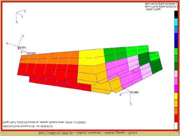
1.Introduction

Aircraft development is a very heavy and complex task which requires continuous
challenge to reach the required level of performance. More and more it is a matter of
collaboration between AIRBUS and its many industrial partners and subcontractors.
It is particularly true for the powerplant configuration, which is the result of many trade-
off studies conducted by AIRBUS and the engine manufacturer.

The design of the powerplant is certainly one of the most difficult problems in
aeronautics because of its high level of multi-disciplinarity and the difficulty of disciplines
involved.
But the compromise exists also for one single discipline, between components : what is
a benefit for the engine, can be penalising for the pylon and vice versa. And even if
AIRBUS is not in charge of engine design and manufacturing, coupled studies including
engine and pylon modifications must be conducted to find the pylon giving the optimum
powerplant configuration.

But to find this global optimum is a tedious task and computational tools are necessary
to aid the decision and provide informations leading to optimal choices.
In the structural design area, MSC.Nastran SOL200 is very useful to evaluate rapidly the
interest of a concept. The guarantee of minimum weight ensures the quality of the
comparison performed between different designs and allows to select in very short
cycles the best solution.

Two studies carried out with SOL200 in the context of the correlated design of engine
and pylon for the AIRBUS A380 are presented in this paper.
They illustrate the classical process of airframe design where stiffness or strength
properties are the first concern of the aircraft manufacturer while stress feasibility is
taken into account in a second time.

2.Context

Two concepts of engine-to-pylon attachments were recently compared by AIRBUS in the
scope of A380 development.

The first concept is traditionally applied on AIRBUS aircraft and consists in attaching the
pylon to the engine core case.
In the second one, the pylon attachment is moved forward, onto the engine fan case.

Let us remind that a pylon is a structural box used to attach the engine to the wing and
that this component is of AIRBUS responsibility.
Pylon role and both concepts are shown in sketches below :

                                   wing                                                   wing

                                                                                  pylon
                           pylon

          fan      core                                      fan           core

                "core" concept                                       "fan" concept
                Figure 1 : Sketches of attachment concepts "core" and "fan".

The problem is to know which powerplant configuration is the best one for the overall
A380 performance.

Discussions between AIRBUS and the engine manufacturer about these two concepts
required strong arguments and many computational studies often in very short cycles.

This is the context of this paper where MSC.Nastran SOL200 revealed itself as being
very satisfactory for these preliminary sizing studies.

3. Stiffness improvement : a use of SOL200 for topology optimisation
and design
3.1 Problem definition

This first study aimed to find a design solution to reduce the bending deformation of the
engine and its rotor for the “core” concept.
AIRBUS designers proposed to add webs and stiffeners to the front part of the core
case, at +/-90° positions, to increase the bending moment of inertia of the engine.
                                                      reinforcement webs
                           fan case
                                                             core case
                           fan case
                           attachment arms

                                                       rear flange

                          Figure 2 : Sketch of the reinforcement principle

A rear flange was also added to support the webs on their back.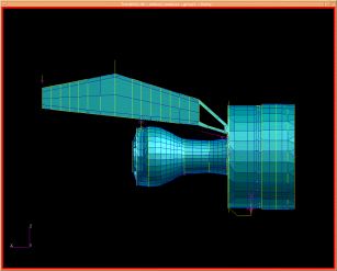
This design principle was then studied by AIRBUS in collaboration with the engine
manufacturer.

In this task, SOL200 was intensively used to determine :
- the location of the additional webs
- the elemental sizes of these stiffened webs (and rear flange)

The objective was to find the best compromise between the minimum weight and the
maximum bending stiffness for the engine.

3.2 Finite element modelling

30 artificial webs were modelled with a 12° step angle and quasi-zero dimensions were
authorised for design variables. This allows SOL200 to remove a web if its contribution
to the bending stiffness is negligible.

Here is a view of the MSC.Nastran finite element model of the engine and pylon :

                     Figure 3 : Engine and pylon finite element model

To measure the engine bending, the difficulty was to remove the rigid body component
of motion. RBAR elements were used to model a rigid bar joining the two bearings of the
low pressure rotor. Then the deflection was measured through SPOINTs pointing at
MPCs which gave the differences of z displacements between the deformed rotor and
the rigid bars. This process gave access to the bending deformation only.

The load case considered was the lift-off case with 85% of maximum thrust at sea-level,
which gives the maximum bending moment. The maximum bending displacement was
found between the two bearings : ∆z at this position was chosen to build a stiffness
indicator for the engine.

3.3 Optimisation process
It was impossible to know a priori which stiffness improvement could be achieved with a
reasonable weight penalty. The objective was to find the maximum stiffness increment
with the minimum weight. To reach this trade-off while designing the engine
reinforcement, a sequence of several optimisation problems was solved with SOL200.
3.3.1 Topology optimisation
The initial problem formulation had not the standard form of weight minimisation under
constraints. Instead, the maximum improvement of engine stiffness with a given weight
addition ∆w* was searched for. ∆w* was chosen as matching the difference on pylon
weights between the “core” and “fan” concepts.
Hence the problem initially solved can be mathematically formulated as :
(P) Max S(λ)
∆w(λ) < ∆w*
∆z 0
with S( λ) = , ∆z0 being the initial bending deflection.
∆z( λ )
λ is the set of design variables composed of web thicknesses and stiffeners cross
sectional areas.
To roughly determine the optimum location of strengthening webs and the maximum
workable stiffness increment, all the 30 webs were first included in the optimisation
problem.
Results showed that the most interesting angular positions were +/- 90° and +/- 36°,
+/-45° around these positions.
To confirm these results a parametric study was performed with 3 webs on the upper
and lower part of the core case. The +/-36° positions were found to be the most efficient
ones.
The stiffness increment found with these local reinforcements was very close to the
maximum value obtained with the complete set of webs. The topology of the
reinforcement could therefore be considered as optimal.
3.3.2 Sizing optimisation
The question now arising was to know if the weight addition was necessary or if there
exists weight penalties less than ∆w* but with a similar stiffness improvement.
To answer this question a parametric study was performed which consists in solving the
problem (P) with different weight additions ∆w*.
An asymptotic behaviour was found for the stiffness improvement according to the
following figure13,5
stiffness increment
13
12,5
12
11,5
11
10,5
10
0,16 0,33 0,67 1
weight ratio
Figure 4 : Asymptotic behaviour of stiffness increment vs. weight supply
A reasonable stiffness target was then defined as being 12,6% increment.
To find the minimum weight required to reach this stiffness target a dual problem
formulation was used and takes the more standard form of weight minimisation under
constraints.
This dual problem can be mathematically formulated as
(P*) Min ∆w(λ)
S(λ) > S*
An optimal value of 0.56 ∆w* was found.
To simplify the design reinforcement, various variable definitions were tested leading to
a final reinforcement with 6 identical webs at (90°,90°+/-36°,-90°+/-36°) positions, with
the same stiffness improvement found as for a heterogeneous solution.
Sizing characteristics are:
Ø outer stiffeners cross sectional area = 0.3 sq.inch
Ø inner stiffeners cross sectional area = 0.6 sq.inch
Ø web thickness = 0.25 inch
Ø rear flange thickness = 0.13 inch
3.5 Discussion
This study illustrates how SOL200 can be used in structural design. Its flexibility allows
to answer rapidly to questions of the designer: position, number, sizing of structural
pieces.It was also demonstrated how difficult the formulation of an optimisation problem can be. An example, classical in stiffness-oriented optimisation is the problem of the asymptotic behaviour of stiffness which can lead to spurious additional weights. The inverse formulation of weight minimisation is more well-posed and must be subsequently considered. More generally, optimisation run is seldom satisfactory and an optimisation problem still involves parametric studies on its own formulation. This study showed that non-negligible engine stiffness increments can be achieved through structural reinforcements. The problem is now to be able to compare weights for different pylon concepts. This is the subject of the next part of this paper. 4. Selection of a concept : a use of SOL200 for rapid weight assessment through preliminary sizing 4.1 Problem definition The problem was to be able to assess the weight for a given pylon so as to compare and make the best choice among different pylon concepts. SOL200 was used in correlation with an automated mesh generator implemented in MSC.Patran with the PCL language. This mesh generator is chained with SOL200 and fed with files of sizing loads and allowables, so as to determine automatically the working weight of the engine pylon. The focus is put here on this automated sizing operation. 4.2 The pylon finite element model
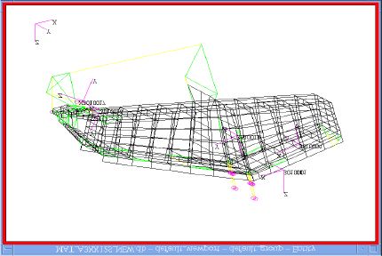
Figure 11 : Pylon finite element model

The finite element model used for the weight assessment is simplified : skins are
represented by CQUAD4s only, according to the equivalent thickness approach. Thus
stability constraints are not directly taken into account. They are included in stress
allowables issued from the designer skill.
The model contains less than 500 elements.
The loading is carried out through a spurious engine made of beam elements enabling
to respect the degrees of freedom concerned by each attachment.

4.3 Definition of design variables

Design variables are defined through group of elements. A design variable is a scaling
factor on a connected set of elements modelling a part of the structure.
As shown in the figure below, these sets can be printed in MSC.Patran with in-house
programmes developed to check the consistency of the design variable definition :

                                                                          P 18
                                                                          P 19
                                                                          P 20
                                                                          P 21

                                                                          P 23
                                                                          P 24
                                                                          P 25
                                                                          P 26
                                                                          P 27

                  Figure 12 : Groups support to design variable definition

4.4 Statement of the optimisation problem

The optimisation problem follows the traditional approach of weight minimisation under
stress constraints giving a set of sizing loads and allowables attached to these loads and
specific parts of the structure :
Min W (λ )
σ i j ≤σ i j *
i = 1, nb of elts
j = 1, nb of loads
Lower bounds are given for thicknesses as given below :
Ø Flanges : 4.0 mm
Ø Skin thicknesses (panel webs) : 2.5 mm
Ø Spar webs : 2.5 mm
Ø Pyramid : 10. mm
Ø Panel supports : 7.0 mm
Sizing loads are of two kinds : 5 flight cases and 4 fan blade out cases are considered.
They are defined as 3 forces and moments applied at the engine centre of gravity.
Design responses are stress Major (σmax), Minor (σmin ) and Max Shear in CQUADs,
side panels and spars, stress σx in pyramid gauges and spar webs.
Gauges are CRODs which are used to measure and control stresses along pylon edges.
Some design constraints were also added between design variables. For example side
panel webs are required to be thinner than the corresponding panel support. This
constraint was formulated as the subsequent inequality :
(tia*λa)/(tip *λp ) < 1
4.5 Automation of the optimisation problem definition
Tools were developed in FORTRAN and PCL to help the user in the definition of the
problem and the tedious generation of the SOL200 Bulk Data.
Loads can be provided in a file or directly in a MSC.Patran window.
Remaining data are attached to groups previously defined.
A table is automatically generated for the user who has to input for each group
associated with a design variable :
- minimum and maximum bounds
- type of stress controlled
- allowable for this constraintFigure 13 : Problem definition window
These tools initially developed in the context of the parametric pylon model to generate
automatically the SOL200 bulk data are fully generic and can be used for any structure
to solve any stress optimisation problem.
However, design constraints such as inequalities between design variables depend on
the application case and must be entered manually.
4.6 Results
As shown on the following figure the results are obtained quickly. Five iterations only are
necessary to convergence which represents less than 2 minutes on a Silicon Graphics
ORIGIN R12000. The weight is first increasing because the initial structure is not
feasible. Consequently, the maximum stress is decreasing.
Figure 14 : Weight and maximum stress historyThe final weight is greater than the initial one, but the starting structure was not feasible.
Optimising a feasible pylon structure showed a weight reduction of 10%. This a typical
weight saving obtained with sizing optimisation which often gives weight savings
between 10 and 15 % in comparison with classical sizing methods.
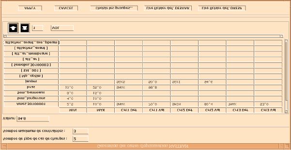
The distribution of stresses as seen below shows for the optimised design a reduced
maximum amplitude and more homogeneous values which is representative of achieved
optimisation results.
Figure 15 : Stress distribution before and after stress optimisation
The preliminary sizing found with SOL200 was carefully checked with designers which
confirmed its consistency.
4.7 Discussions
Comparisons were performed with an in-house implementation of the Fully Stressed
Design approach. It shows that FSD converges with difficulty and does not give
minimum weights. The weight obtained through SOL200 optimisation is 10% lighter.
SOL200, even if more sophisticated was preferred to build the automation sizing
procedure of the automated MSC.Patran mesh generator.
This procedure can obviously be generalised to more sophisticated FEMs in more
advanced design phases. The set of loads is not limited and SOL200 automatically
computes the critical loads using the active constraint principle.
Hence SOL200 also gives large cycle reductions : two weeks are necessary for a design
engineer to size the pylon and compute the load envelop with classical tools and only
two iterations can be performed. SOL200 requires only 2 minutes to perform a better
work, leading to convergence and minimum weight !
5.Conclusion
Attempt was made in this paper to show how SOL200 can be used profitably at the
beginning of an aircraft development to aid the decision in the structural design of
aircraft components. Many applications of SOL200 to A380 have already beenperformed in AIRBUS. Most of the components have been impacted (wing, fuselage, engine pylons, landing gear bays …). Among the numerous studies carried out, two applications to the powerplant optimisation were selected. They demonstrate the performance of SOL200 in two important areas of structural design : - design of a structure for stiffness requirements - preliminary stress sizing to assess the weight of a component In both of them, SOL200 showed its efficiency and gave strong arguments to choose the best design solutions and helped AIRBUS and its industrial partners to reach the best level of performance for the A380. Moreover two kinds of SOL200 utilisation were demonstrated - free use showing how it can be difficult to solve an optimisation problem without optimisation expertise essentially in the statement of the problem, which is often full of traps - encapsulated use where a previous tuning of the problem definition and an automated data generation makes SOL200 accessible to non-expert users.
Both modes of utilisation gives to SOL200 the required flexibility to be intensively applied
in A380 development on powerplant configuration as well as any A380 component
(wing, fuselage, …). SOL200 and more generally optimisation methods and tools will
then give best structural solutions for A380, with minimum weights and in reduced
cycles. This is a major contribution to AIRBUS objective: to issue the most competitive
aircraft above 400 seats.

But SOL200 can still be improved and here are proposals for further developments :
- optimisation data definition is tedious and could be simplified and facilitated through
   extensions of MSC.Patran SOL200 interface (potentially customised to aeronautical
   applications).
- algorithms can be improved and enriched (discrete / global optimisation)
-  a tool to update the Bulk Data after optimisation is bitterly missing
-  a software framework could be built around SOL200 to integrate non-MSC analysis
   codes into the optimisation process : in stress optimisation for example, finite
   element results must generally be mixed with skill tool results (stability, damage
   tolerance …).
You can also read