TOWARDS AERODYNAMIC CONTROL OF MINIATURE ROCKETS WITH - University ...
←
→
Page content transcription
If your browser does not render page correctly, please read the page content below
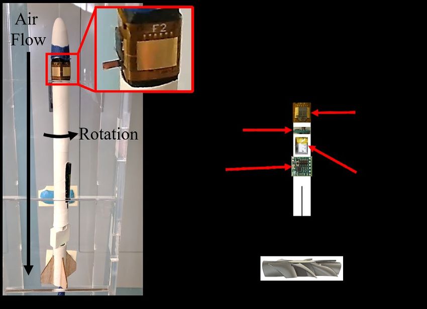
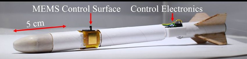
TOWARDS AERODYNAMIC CONTROL OF MINIATURE ROCKETS WITH
 MEMS CONTROL SURFACES
 Ahad M. Rauf, Brian G. Kilberg, Craig B. Schindler, Sang A Park, and Kristofer S. J. Pister
 Berkeley Sensor & Actuator Center
 University of California, Berkeley, California, USA

ABSTRACT
 We demonstrate a MEMS-actuated aerodynamic
control surface integrated into an untethered 16.9 g, 20 cm
rocket. The system’s flight performance was characterized
inside a wind tunnel. The actuator system generates 3.6
μNm of torque about the rocket’s body axis in 13.3 m/s Figure 1: The fully assembled rocket, consisting of a
airflow with 5.1° angle of attack, inducing a maximum roll MEMS control surface and its 2x4 mm2 steel airfoil, a
velocity of 100°/s. This is the first electrostatic inchworm single-cell LiPo battery, and control electronics.
motor-actuated MEMS control surface to perform
aerodynamic maneuvers in a self-contained rocket body. It highlights changes made in the assembly process to
 prevent out-of-plane forces from dislocating silicon
 mechanisms, as well as a higher-density electrostatic
KEYWORDS inchworm motor design. This paper also discusses the
 MEMS Airfoils, Miniature Rockets, Micro-Air procedure for integrating the MEMS actuator into a fully
Vehicles, Electrostatic Inchworm Motors contained 16.9 g, 20 cm rocket system, which is composed
 of a battery, wireless sensor node, IMU, and high voltage
INTRODUCTION buffer board for running the inchworm motors at 80 V.
 Miniature autonomous rockets provide a natural
solution to problems such as micro-air vehicle (MAV) THEORY AND DESIGN
swarm interception and rapid area surveillance, where Aerodynamics and Airfoil Design
conventional systems with larger sizes or ballistic Most aircraft use control surfaces such as ailerons,
trajectories tend to be either expensive or unportable [1], elevons, and canards to control their trajectories. For small
[2]. These rockets benefit from recent improvements in angles of attack ( < 15°), the lift force produced by
battery energy density and the decreasing size, power, and these airfoils can be modeled using thin airfoil theory.
cost of digital computation and sensors, which could enable
low-cost, highly maneuverable autonomous MAVs with 1
size scales
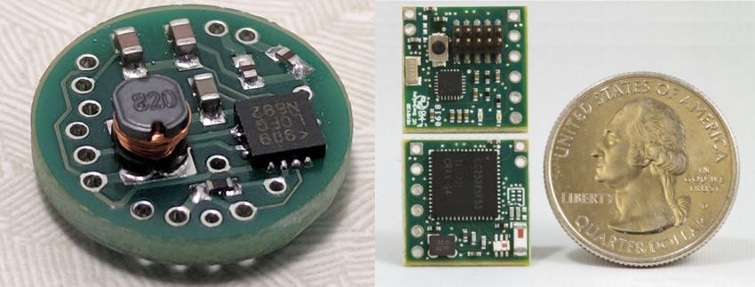
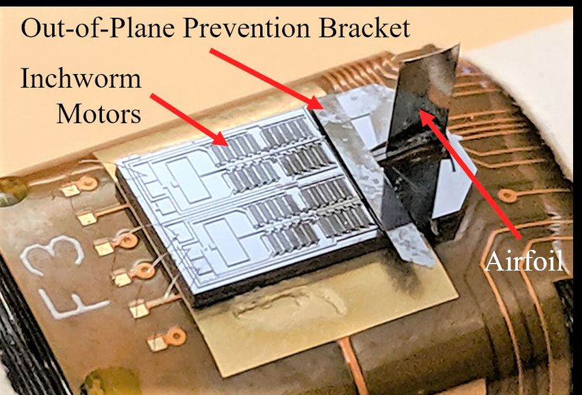
Figure 3: The assembled MEMS control surface.

Figure 2: (Left) Schematic of half of the MEMS actuator
mechanism. The inchworm motor linearly actuates the
rotary pin joints, which rotate the airfoil slot. (Right) A
microscopic photograph of the airfoil slot after rotation.

MEMS Actuator Mechanism
 The MEMS actuator, fabricated in a simple 2-mask
silicon-on-insulator (SOI) process, comprises a pair of
 Figure 4: (Left) The 13 mm diameter high voltage buffer
electrostatic inchworm motors and rotary pin joints. The
 board. (Right) The MIMSY control and wireless node.
inchworm motors pull on a lever arm attached to the airfoil
slot, which rotates the airfoil (Figure 2). We applied the One problem we found in practice with this process
higher-density electrostatic inchworm motor design was that any curvature in the flexible PCB or flexibility in
described in [10] to increase our force density by 65% the substrate substantially decreased our wire bonding
compared to previous work done in [9], as measured by the yield. To solve this, we attached a 0.5 mm thick carbon
ratio between the capacitive finger overlap area and the fiber stiffener behind the ground plane before the epoxy
entire motor’s layout area. This redesign allowed us to step, which greatly improved our wire bonding yield.
shrink the MEMS device’s area by 21% from 9x7 mm2 to Our placement of the airfoil closer to the rocket’s front
5x9 mm2, realizing our design goal of a MEMS actuator end follows from the design of canard guided missiles,
that can fit on a 6 mm diameter rocket [8]. which feature motorized frontal control surfaces and
 Previous work has attempted to prevent out-of-plane passively stabilizing tail fins. By shifting the rocket’s
forces from dislocating the silicon mechanisms by gluing a center of pressure forward, this design model improves the
small silicon piece over the rotary pin joints [9]. One rocket’s response time and control surface output gain,
problem we found with this process was that commercial reducing the required control surface hinge moment
silver epoxy or superglue would often wick a significant compared to equivalent tail fin controllers and decreasing
distance from its initial application position, immobilizing the rocket’s miss distance against mobile targets [11]. The
silicon mechanisms. To solve this issue, we added extra design also facilitates rocket assembly by keeping the
slots to either side of the MEMS device, where we slotted control surfaces and electronics far from the rocket engine.
in a bracket that lay over the lever arm and pin joint
structures (Figure 3). The bracket is secured via epoxy only Electronics and Controls
at the sides to prevent wicking from affecting any mobile The inchworm motors require 45 V–110 V to operate,
MEMS components. We fabricated the brackets using the which poses a power supply challenge at small scales. To
same 2-mask SOI process, and we observed no degradation solve this, we developed an 80 V high voltage buffer board
in device performance after placing the bracket. based on Linear Technology’s LT3482 DC/DC boost
 converter. The board’s 13 mm diameter footprint enables it
INTEGRATED ROCKET DESIGN to be mounted normal to the rocket’s body axis, presenting
MEMS Actuator Mechanism a 4x area decrease and a 5 cm rocket length reduction
 To mount the assembled control surfaces onto the compared to previous iterations [9] (Figure 4).
rocket, we developed a custom flexible printed circuit The rocket’s onboard control and wireless
board with room for 4 control surfaces (Figure 3). The communication are handled by the Micro Inertial
MEMS device substrate is electrically connected via silver Measurement System (MIMSY), a 16x16 mm2 node with
epoxy to a large ground plane, and the other control signals an Arm Cortex-M3 microprocessor, 802.15.4 wireless
are routed from the PCB to the control surface via standard transceiver, and a 9-axis IMU [12]. Input power was
wire bonding techniques. The assembled flexible PCB is supplied via a 40 mAh single-cell lithium polymer battery,
then wrapped around a custom 3D-printed fuselage and which can power the IMU and a constantly running TX
friction fit into the rocket body (Figure 1). radio broadcast for roughly an hour after the rocket lands.
Figure 1: Roll angle vs. time data for individual rocket experiments in the wind tunnel, measured visually. The plots
show the difference between the rocket’s roll with and without an actuated fin. From left to right, the experiments were
conducted at = 2.6 μNm, 4.9 μNm, and 0.51 μNm. The 5.1° and 10.5° experiments were conducted in 13.3 m/s
airflow while the 19.6° experiment was conducted in 20.1 m/s airflow, which explains the latter’s large roll angles.

AERODYNAMIC PERFORMANCE
 The system was tested inside a wind tunnel with 13.3
m/s airflow. Because the rocket’s moment of inertia about
its roll axis is much smaller than about its pitch or yaw
axes, for ease of measurement we focused on measuring
the roll generated from the airfoil’s aerodynamic lift. The
full testing setup is shown in Figure 6. The rocket’s vertical
suspension by tensioned string in the wind tunnel allowed
us to model the system as a torsional pendulum.

 ∑ = ̈ = − (4)

 = (5)

where the moment of inertia along the roll axis,
 Figure 6: (Left) Lift force is generated when the fin is
is the suspension string’s torsional coefficient, is the
 rotated, causing the entire rocket to roll along its axis.
string’s shear modulus, is the string’s second moment of
 (Right) Schematic of the integrated rocket system inside a
area ( = 4 /2 for a circular cross-section), and is the
 wind tunnel.
string’s length. We used 0.005” diameter Berkley XLPS2-
15 fishing line for our suspension string. To characterize Angle of , , (μNm)
the fishing line’s shear modulus, we measured its period of Attack (°) (μNm) (N=3 trials)
 (μNm)
oscillation as a torsional pendulum given a test load of
 5.11 4.2 3.6 0.035
known moment of inertia. We fitted this data to Equation 5
 10.52 8.6 7.8 0.23
to show that = 6.9 for our fishing line with an 2
 19.62 15.8 7.8 0.13
value of 0.96, indicating high convergence to the theory. _

 To measure the control surface’s output torque , Table 1: Output torque from the fin’s lift force, measured
we measured the rocket’s equilibrium position about its roll across 3 trials for each angle of attack. All measurements
axis at different wind speeds and angles of attack (Figure were normalized to match a 2x4 mm2 airfoil’s area and a
5). We tested fins at three different angles of attack: the wind speed of 13.3 m/s. The rockets tested were either
5.1° fin is electronically actuated, while the 10.5° and 19.6°
 1
 electronically actuated or 2statically positioned.
fins are glued into place as control experiments. To account
for any asymmetry in the rocket’s construction, we We simulated the rocket’s launch performance with an
measured the difference between the rocket’s roll with and Estes A3-4T engine using the software OpenRocket [13].
without the battery connected (or, in the case of the The rocket should have a maximum range of 360 m, a top
statically positioned fins, by replacing the MEMS actuator speed of 79 m/s, and the ability to execute 10g maneuvers.
with a finless one). We also measured the torsional
coefficient and airflow speed for each setup. FUTURE VISION
 Table 1 factors in all these measurements to calculate The eventual design of a cigarette-sized rocket would
the output torque on the rocket body. Experimental airfoil comprise the Single-Chip Micro Mote (SCμM) [5] for
output torque is shown to match reasonably well with the communication and computation, an IMU for navigation,
theory (Equation 2) for angles of attack under 10°, and the MEMS control surfaces for control, a miniaturized camera
deviation between 10-20° angle of attack also matches the for sensing, and a rocket motor like in [4] for propulsion.
expected limit of thin airfoil theory from nonidealities. The high voltage circuitry will be replaced by millimeter-
These results present a promising case for our ability to use scale high-voltage DC/DC converter integrated circuits
linear control models to accurately control the rocket [14]. Power will be supplied via two 1.5 V coin cell
during flight. batteries like the SR521SW. Rocket control complexity
 will scale from roll stabilization using one control surface
Component Current Dimensions Current Mass Projected Dimensions Projected Mass
 (mm3) (g) (mm3) (g)
 Control Surface 5x4x9 0.058 5x4x9 0.058
 Battery 10 x 4 x 20 1.53 5.8 x 5.8 x 4.3 0.46
 Power Circuitry 13 x 13 x 5 1.27 3 x 3 x 0.3 [14] 0.071 [14]
 Control Electronics 16 x 4 x 16 1.24 2 x 3 x 0.3 [5] 0.047 [5]
 Rocket Engine 13 x 13 x 45 8.5 6.4 x 6.4 x 60 [4] 1.4 [4]
 Total 15 x 15 x 201 19.6 6.4 x 6.4 x 104 5.7
Table 2: Current and projected rocket volumetric dimensions and mass with future scaling of rocket components. The
control surfaces presented in this paper are well suited for miniature rockets as is, and incorporating the referenced
circuitry and rocket engine designs could further reduce rocket size. The total row includes the above factors plus the
rocket’s nose cone, electrical wiring, and fuselage.

to full roll, pitch, and yaw control using 2-4 control Transceiver, sub-mW BLE Compatible Beacon
surfaces spaced evenly around the rocket’s circumference. Transmitter, and Cortex M0," Symposium on VLSI
The rocket would be 10 cm long, 6 mm in diameter, and Circuits, June 9-14, 2019, pp. C88–C89.
would have 400 m range, a top speed of 25 m/s, and the [6] C. Folk and C.-M. Ho, "Micro-actuators for control
ability to execute 10g manuevers [8]. The lack of of delta wing with sharp leading edge," Aerospace
performance degradation even at lower flight speeds Sciences Meeting and Exhibit, January 8-11, 2001.
highlights the maneuverability improvements of rocket
miniaturization. This scaling is summarized in Table 2. [7] R. J. Wood, E. Steltz, and R. S. Fearing, "Optimal
 energy density piezoelectric bending actuators,"
 Sensors and Actuators A: Physical, April 13, 2005,
CONCLUSION vol. 119, no. 2, pp. 476-488.
 We demonstrated the integration of MEMS
 [8] B. G. Kilberg, D. S. Contreras, J. Greenspun, and K.
aerodynamic control surfaces into a fully integrated
 S. Pister, "MEMS aerodynamic control surfaces for
miniature rocket. Improvements in assembly techniques
 millimeter-scale rockets," International Conference
and MEMS design substantially improved yield, helping to
 on Manipulation, Automation and Robotics at Small
create MEMS aerodynamic actuators ready for use in real-
 Scales (MARSS), August 8, 2017, pp. 1-5.
world systems. These results present a promising case for
the ability of MEMS aerodynamic control surfaces to [9] B. Kilberg, D. Contreras, J. Greenspun, H. Gomez,
sufficiently control miniature rockets during actual E. Liu, and K. S. J. Pister, "MEMS Airfoil with
launches, and our higher force density actuators indicate Integrated Inchworm Motor and Force Sensor," in
future potential for continued size reduction. Hilton Head, Hilton Head Island, South Carolina,
 May 2018.
ACKNOWLEDGMENTS [10] C. B. Schindler, J. T. Greenspun, H. C. Gomez, and
 The authors would like to thank the entire Pister group K. S. J. Pister, "A Jumping Silicon Microrobot with
and Swarm Lab. This research was financially supported Electrostatic Inchworm Motors and Energy Storing
by the Berkeley Sensor & Actuator Center. MEMS devices Substrate Springs," Transducers Eurosensors
were fabricated in the Marvell Nanofabrication Laboratory XXXIII, June 23-27, 2019, pp. 88-91.
at UC Berkeley. [11] S. Gutman, “Superiority of Canards in Homing
 Missiles,” IEEE Transactions on Aerospace and
REFERENCES Electronic Systems, July 2003, vol. 39, no. 3, pp.
 740–746.
[1] D. Sathyamoorthy, "A review of security threats of
 unmanned aerial vehicles and mitigation steps," [12] C. B. Schindler, D. S. Drew, B. G. Kilberg, F. M. R.
 Journal of Defence and Security, October 2015, vol. Campos, S. Yanase and K. S. J. Pister, "MIMSY:
 6, no. 1, pp. 81-97. The Micro Inertial Measurement System for the
 Internet of Things," World Forum on Internet of
[2] D. S. Drew, B. Kilberg, and K. S. J. Pister, "Future
 Things (WF-IoT), April 15-18, 2019, pp. 329–334.
 Mesh-Networked Pico Air Vehicles," International
 Conference on Unmanned Aircraft Systems [13] Niskanen, Sampo. “Development of an Open
 (ICUAS), June 13-16, 2017, pp. 1075–1082. Source model rocket simulation software,” M.S.
 thesis, Helsinki University of Technology,
[3] D. Teasdale, "Solid Propellant Microrockets," M.S.
 Department of Engineering Physics, May 2009.
 thesis, UC Berkeley, Department of Electrical
 Engineering and Computer Sciences, May 2000. [14] J. T. Stauth, "Pathways to mm-Scale DC-DC
 Converters: Trends, Opportunities, and
[4] M. Kovač, M. Bendana, R. Krishnan, J. Burton, M.
 Limitations," IEEE Custom Integrated Circuits
 Smith, and R. J. Wood, "Multi-stage Micro Rockets
 Conference (CICC), April 8-11, 2018, pp. 1-8.
 for Robotic Insects," in Robotics: Science and
 Systems VIII, Sydney, Australia, 2012.
[5] F. Maksimovic et al., "A Crystal-Free Single-Chip CONTACT
 Micro Mote with Integrated 802.15.4 Compatible A. M. Rauf, ahadrauf@berkeley.edu
You can also read