AIR CONDITIONER INSTALLATION MANUAL
←
→
Page content transcription
If your browser does not render page correctly, please read the page content below
ENGLISH
                                                                                   ITALIANO
                                                                                   ESPAÑOL
                                                                                   FRANÇAIS
INSTALLATION MANUAL
AIR CONDITIONER                                                                    DEUTSCH
• Please read this installation manual completely before installing the product.
• Installation work must be performed in accordance with the national wiring
  standards by authorized personnel only.
• Please retain this installation manual for future reference after reading it
  thoroughly.
                                                                                   PORTUGUÊS

TYPE : Air-to-Water Heat Pump

P/NO : MFL63285302                                                 www.lg.com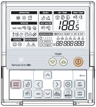
Air-to-Water Heat Pump Installation Manual

               TABLE OF CONTENTS
ITEMS INSIDE PRODUCT BOX ..........................................................................................5
   INDOOR UNIT BOX ......................................................................................................................5
   OUTDOOR UNIT BOX ..................................................................................................................5

PREFACE.............................................................................................................................6

1. SAFETY PRECAUTION...................................................................................................7
   WARNING .....................................................................................................................................7
     INSTALLATION WARNING .....................................................................................................7
     OPERATION WARNING .........................................................................................................8
   CAUTION ......................................................................................................................................9
     INSTALLATION CAUTION ......................................................................................................9
     OPERATION CAUTION ..........................................................................................................9

2. GENERAL INFORMATION ............................................................................................10
   MODEL INFORMATION ..............................................................................................................11
   ACCESSORIES ..........................................................................................................................12
      ACCESSORIES SUPPORTED BY LG Electronics ...............................................................12
      ACCESSORIES SUPPORTED BY 3rd PARTY COMPANIES ..............................................12
   TYPICAL INSTALLATION EXAMPLE ..........................................................................................13
      CASE 1..................................................................................................................................13
      CASE 2..................................................................................................................................14
      CASE 3 .................................................................................................................................15
   CYCLE DIAGRAM ......................................................................................................................16
      REFRIGERANT CYCLE........................................................................................................16
      WATER CYCLE.....................................................................................................................18
   PARTS AND DIMENSIONS ........................................................................................................19
      INDOOR UNIT (EXTERNAL) ................................................................................................19
      INDOOR UNIT (INTERNAL)..................................................................................................21
      OUTDOOR UNIT (EXTERNAL) ............................................................................................21
   CONTROL PARTS ......................................................................................................................24
      CONTROL BOX : INDOOR UNIT..........................................................................................24
      CONTROL PANEL ................................................................................................................25
      WIRING DIAGRAM : INDOOR UNIT.....................................................................................25
      CIRCUIT DIAGRAM : INDOOR UNIT ...................................................................................25
      WIRING DIAGRAM : OUTDOOR UNIT.................................................................................25
      WIRING DIAGRAM : INDOOR UNIT AND OUTDOOR UNIT (INCL. FIELD WIRING) .........26

2 Air-to-Water Heat Pump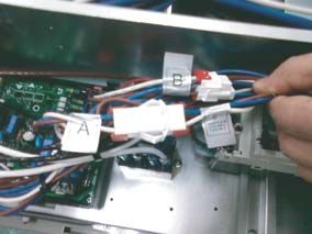
3. INSTALLATION OF OUTDOOR UNIT ...........................................................................30
   CONDITIONS WHERE OUTDOOR UNIT IS INSTALLED..........................................................30
   DRILL A HOLE IN THE WALL.....................................................................................................30

                                                                                                                                                   ENGLISH
   INSTALLATION AT SEASIDE .....................................................................................................31
   SEASONAL WIND AND CAUTIONS IN WINTER ......................................................................31

4. INSTALLATION OF INDOOR UNIT ...............................................................................32
   CONDITIONS WHERE INDOOR UNIT IS INSTALLED..............................................................32
     GENERAL CONSIDERATIONS ............................................................................................32
     SERVICE SPACE..................................................................................................................32
     MOUNTING TO WALL ..........................................................................................................33
     WATER VOLUME AND WATER PUMP CAPACITY .............................................................34
     WATER VOLUME AND EXPANSION VESSEL PRESSURE................................................35
     WATER QUALITY .................................................................................................................36
   CONDITIONS IF ACCESSORIES ARE INSTALLED..................................................................37
     THERMOSTAT ......................................................................................................................37
     REMOTE AIR TEMPERATURE SENSOR ........................................................................... 37
     SANITARY WATER TANK AND SANITARY WATER TANK KIT / SOLAR THERMAL KIT ...38
     3WAY VALVE(2WAY VALVE) ................................................................................................40

5. PIPING AND WIRING FOR OUTDOOR UNIT ...............................................................41
   REFRIGERANT PIPING .............................................................................................................41
      CONSTRAINTS IN PIPE LENGTH AND ELEVATION ..........................................................41
      PREPARATION FOR PIPING ...............................................................................................42
      CONNECTING PIPE TO INDOOR UNIT ..............................................................................43
      CONNECTING PIPE TO OUTDOOR UNIT ..........................................................................43
   ELECTRICAL WIRING................................................................................................................46
      WIRE SPECIFICATION.........................................................................................................46
      CIRCUIT BREAKER SPECIFICATION .................................................................................47
      WIRING PROCEDURE FOR POWER CABLE AND CONNECTING CABLE.......................47
   FINALIZING ................................................................................................................................49
      PIPE FORMING ....................................................................................................................49
   LEAKAGE TEST AND EVACUATION.........................................................................................50
      PREPARATION .....................................................................................................................50
      LEAKAGE TEST ...................................................................................................................50
      EVACUATION........................................................................................................................51

6. PIPING AND WIRING FOR INDOOR UNIT ...................................................................52
   WATER PIPING AND WATER CIRCUIT CONNECTION............................................................52
     GENERAL CONSIDERATIONS ............................................................................................52
     WATER PIPING AND WATER CIRCUIT CONNECTION......................................................52
     WATER CHARGING .............................................................................................................54
     PIPE INSULATION ................................................................................................................54

                                                                                                                 Installation Manual 3
ELECTRICAL WIRING................................................................................................................55
GENERAL CONSIDERATION...............................................................................................55
TERMINAL BLOCK INFORMATION .....................................................................................56
CONNECTING WITH OUTDOOR UNIT ...............................................................................58
ELECTRIC HEATER WIRING ...............................................................................................58
7. ACCESSORIES INSTALLATION...................................................................................59
BEFORE INSTALLATION ...........................................................................................................59
THERMOSTAT ............................................................................................................................59
GENERAL INFORMATION ...................................................................................................59
HOW TO WIRE THERMOSTAT ............................................................................................60
FINAL CHECK.......................................................................................................................61
SANITARY WATER TANK AND SANITARY WATER TANK KIT/SOLAR THERMAL KIT ...........62
GENERAL INFORMATION ...................................................................................................62
HOW TO INSTALL SANITARY WATER TANK ......................................................................63
HOW TO INSTALL SANITARY WATER TANK KIT ...............................................................64
HOW TO WIRE SANITARY WATER TANK HEATER............................................................66
HOW TO INSTALL SOLAR THERMAL KIT...........................................................................67
DRY CONTACT...........................................................................................................................67
REMOTE TEMPERATURE SENSOR.........................................................................................67
3WAY VALVE ..............................................................................................................................68
HOW TO WIRE 3WAY VALVE ..............................................................................................68
FINAL CHECK.......................................................................................................................68
2WAY VALVE ..............................................................................................................................69
GENERAL INFORMATION ...................................................................................................69
HOW TO WIRE 2WAY VALVE ..............................................................................................69
FINAL CHECK.......................................................................................................................69
8. SYSTEM SET-UP ...........................................................................................................70
DIP SWITCH SETTING...............................................................................................................70
GENERAL INFORMATION ...................................................................................................70
DIP SWITCH INFORMATION................................................................................................71
CONTROL PANEL SETTING......................................................................................................74
HOW TO ENTER INSTALLER SETTING MODE..................................................................74
SUMMARY ............................................................................................................................76
COMMON SETTING .............................................................................................................81
TEMPERATURE RANGE SETTING .....................................................................................82
TEMPERATURE CONTROL PARAMETER SETTING AND ETC.........................................83
9. CHECK POINTS, MAINTENANCE AND TROUBLESHOOTING..................................88
CHECK LIST BEFORE STARTING OPERATION.......................................................................88
MAINTENANCE ..........................................................................................................................89
TROUBLESHOOTING ................................................................................................................90
TROUBLESHOOTING FOR PROBLEM WHILE OPERATION.............................................90
4 Air-to-Water Heat PumpItems inside product box
Items Inside Product Box
Thank you for choosing LG Electronics Air-to-Water Heat Pump
ENGLISH
Before starting installation, please make it sure that all parts are found inside the product box.
INDOOR UNIT BOX
Item Image Quantity Item Image Quantity
Indoor unit 1 Shut-off valve 2
Installation Installation
Manual INSTALLATION MANUAL
AIR CONDITIONER
• Please read this installation manual completely before installing the product.
1 plate 1
• Installation work must be performed in accordance with the national wiring
standards by authorized personnel only.
• Please retain this installation manual for future reference after reading it
thoroughly.
TYPE :
www.lg.com
Owner's Installation
1 1
Manual OWNER’S MANUAL
AIR CONDITIONER
Please read this manual carefully before operating
your set and retain it for future reference.
Sheet
TYPE : WALL MOUNTED
www.lg.com
OUTDOOR UNIT BOX
Item Image Quantity
Outdoor unit
U3 Chassis
(Product heating capacity : 1
12kW,14kW,16kW)
Outdoor unit
UE1 Chassis
(Product heating capacity : 1
9kW)
Outdoor Unit
AHUW096A1(U4 Chassis)
(Product heating capacity : 1
9kW)
Installation Manual 5Preface
Preface
This installation manual is to present information and guide about understanding, installing,
and checking .
Your careful reading before installation is highly appreciated to make no mistake and to prevent potential risks.
The manual is divided into nine chapters. These chapters are classified according to installation procedure.
See the table below to get summarized information.
Chapters Contents
• Warning and Caution concerned with safety.
Chapter 1 • This chapter is directly related with human safety. We STRONGLY
recommend reading this chapter carefully.
• Fundamental knowledge about
• Model identification, accessories information, refrigerant and water cycle
Chapter 2
diagram, parts and dimensions, electrical wiring diagrams, etc.
• This chapter is important to understand
• Installation about the outdoor unit.
Chapter 3
• Installation location, constraints on installation site, etc
• Installation about the indoor unit.
Chapter 4 • Installation location, constraints on installation site, etc
• Constrains when accessories are installed
• How to perform piping (for refrigerant) and wiring at the outdoor unit.
Chapter 5 • Refrigerant pipe connection between the indoor unit and the outdoor unit.
• Electrical wiring at the outdoor unit.
• How to perform piping (for water) and wiring at the indoor unit.
• Water pipe connection between the indoor unit and pre-built under floor
water loop pipe.
• Electrical wiring at the indoor unit.
Chapter 6 • System set-up and configuration.
• As many control parameters of is adjustable by control panel,
deep understanding about this chapter is required to secure the operation
flexibility of
• For more detailed information, please read the separate OPERATION
MANUAL to use control panel and adjust control parameters.
• Information about supported accessories
• Specification, Constraints, and wiring are described.
Chapter 7
• Before purchasing accessories, please find supported specification to buy
proper one.
Chapter 8 • Test operation and check point while test running.
• Check points before starting operation are explained.
Chapter 9 • Troubleshooting, maintenance, and error code list are presented to correct
problems.
REMARK : ALL CONTENTS OF THIS MANUAL ARE SUBJECT TO CHANGE WITHOUT NOTICE.
TO GET THE LATEST INFORMATION, PLEASE VISIT LG ELECTRONICS WEB SITE
www.lgservice.com
6 Air-to-Water Heat PumpSafety Precautions
1. Safety Precautions
To prevent injury to the user or other people and property damage, the following instructions must be
ENGLISH
followed.
n Be sure to read before installing the product.
n Be sure to observe the cautions specified here as they include important items related to safety.
n Incorrect operation due to ignoring instruction will cause harm or damage. The seriousness is classified
by the following indications.
This symbol indicates the possibility of death or serious injury.
This symbol indicates the possibility of injury or damage to properties only.
n Meanings of symbols used in this manual are as shown below.
Be sure not to do.
Be sure to follow the instruction.
n Installation
Do not use a defective or For electrical work, contact Always ground the product.
underrated circuit breaker. the dealer, seller, a qualified
Use this appliance on a electrician, or an Authorized
dedicated circuit. Service Center.
• There is risk of fire or electric • There is risk of fire or electric • There is risk of fire or electric
shock. shock. shock.
Install the panel and the cover Always install a dedicated Use the correctly rated
of control box securely. circuit and breaker. breaker or fuse.
• There is risk of fire or electric • Improper wiring or installation • There is risk of fire or electric
shock. may cause fire or electric
shock
Do not modify or extend the Do not install, remove, or Be cautious when
power cable. reinstall the unit by yourself unpacking and installing the
(customer). product.
• There is risk of fire or electric • There is risk of fire, electric • Sharp edges could cause injury.
shock. shock, explosion, or injury Especially careful on the product
edges and the fins on the heat
exchanger.
Installation Manual 7Safety Precautions
For installation, always Do not install the product on Be sure the installation area
contact the dealer or an a defective installation does not deteriorate with
Authorized Service Center. stand. age.
• There is risk of fire, electric • It may cause injury, accident, • If the base collapses, the product
shock, explosion, or injury. or damage to the product. could fall with it, causing property
damage, product failure, and
personal injury.
n Operation
Do not let the product run for a Take care to ensure that Do not place anything on
long time when the humidity is power cable could not be the power cable.
very high and a door or a pulled out or damaged
window is left open. during operation.
• Moisture may be condensed • There is risk of fire or electric • There is risk of fire or electric
and wet or damage furniture. shock. shock.
Do not plug or unplug the power Do not touch (operate) the Do not place a heater or other
supply plug during operation. product with wet hands. appliances near the power cable.
• There is risk of fire or electric • There is risk of fire or electric • There is risk of fire or electric
shock. shock. shock.
Do not allow water to run Do not store or use flammable Do not use the product in a
into electric parts. gas or combustibles near the tightly closed space for a
product. long time.
• There is risk of fire, failure of • There is risk of fire or failure • Oxygen deficiency could
the product, or electric shock. of product. occur.
When flammable gas leaks, If strange sounds, or small or Stop operation and close the window
turn off the gas and open a smoke comes from product, turn in storm or hurricane. If possible,
window for ventilation the breaker off or disconnect the remove the product from the window
before turn the product on. power supply cable. before the hurricane arrives.
• There is risk of explosion or • There is risk of electric shock • There is risk of property
fire. or fire. damage, failure of product, or
electric shock.
Do not open the front cover of When the product is soaked Be cautious that water could
the indoor unit while operation. (flooded or submerged), not be poured to the product
(Do not touch the electrostatic contact an Authorized directly.
filter, if the unit is so equipped.) Service Center.
• There is risk of physical injury, • There is risk of fire or electric • There is risk of fire, electric
electric shock, or product shock. shock, or product damage.
failure.
Ventilate the product from Turn the main power off Take care to ensure that
time to time when operating when cleaning or nobody could step on or fall
it together with a stove, etc. maintaining the product. onto the outdoor unit.
• There is risk of fire or electric • There is risk of electric shock. • This could result in personal
shock. injury and product damage.
8 Air-to-Water Heat PumpSafety Precautions
Special warning about no operation for long-time
• If the product is not used for long time, we strongly recommend NOT TO
SWITCH OFF THE POWER SUPPLY to the product.
ENGLISH
• If power is not supplied, some special product-protecting actions (such as
water pump anti-locking) will not performed.
n Installation
Always check for gas Do not install the product Keep level even when
(refrigerant) leakage after where it will be exposed to installing the product.
installation or repair of sea wind (salt spray)
product. directly.
• Low refrigerant levels may cause • It may cause corrosion on the • To avoid vibration or water
failure of product. product. Corrosion, particularly on leakage.
the condenser and evaporator fins,
could cause product malfunction or
inefficient operation.
Do not install the product where the noise Use two or more people to lift and transport
or hot air from the outdoor unit could the product.
damage the neighborhoods.
• It may cause a problem for your neighbors. • Avoid personal injury.
n Operation
Do not lay on the cooled Do not use the product for Do not block the outlet of air
floor for long time when the special purposes, such as flow.
product is in cooling preserving foods, works of art,
operation. etc. It is a consumer product, not
a precision refrigeration system.
• This could harm to your health. • There is risk of damage or loss of • It may cause product failure.
property.
Use a soft cloth to clean. Do Do not step on or put Do not insert hands or other
not use harsh detergents, anything on the product. objects into the product
solvents, etc. (outdoor units) while it is operating.
• There is risk of fire, electric • There is risk of personal injury • There are sharp and moving
shock, or damage to the plastic and failure of product. parts that could cause personal
parts of the product. injury.
Use a firm stool or ladder At low outdoor temperature,
when cleaning or the product will display
maintaining the product. “CH44”
• Be careful and avoid personal • It may cause a problem for
injury. product.
Installation Manual 9General Information
2. General Information
With advanced inverter technology, is suitable for applications like under floor heating,
under floor cooling, and hot water generation. By Interfacing to various accessories user can
customize the range of the application.
In this chapter, general information of is presented to identify the installation
procedure. Before beginning installation, read this chapter carefully and find helpful information on
installation.
Model Information
Model number nomenclature
A H — W 0 9 6 A 0
Series Number(N : Nordic Model)
Chassis Name
Electrical ratings
6 : 1 phase 220-240V AC 50Hz 8 : 3 phase 380-415V AC 50Hz
Heating Capacity (kW)
09 : 9kW 12 : 12kW 14 : 14kW 16 : 16kW
Model Type
W : Inverter Heat Pump H : Heat Pump
Classification
N : Indoor Unit U : Outdoor Unit – : Set
Air-to-Water Heat Pump for R410A
A H N W 0 9 A 0 6 A 0
Series Number
Chassis Name
Heater Capacity (kW)
04 : 4kW 06 : 6kW
Heater Electrical ratings
6 : 1 phase 220-240V AC 50Hz
8 : 3 phase 380-415V AC 50Hz
A : 3 phase 220V AC 50Hz
Heating Capacity (kW)
09 : 9kW 12 : 12kW 14 : 14kW 16 : 16kW
Model Type
W : Inverter Heat Pump H : Heat Pump
Classification
N : Indoor Unit U : Outdoor Unit — : Set
Air-to-Water Heat Pump for R410A
10 Air-to-Water Heat PumpGeneral Information
Model name and related information
Model Name Built-In Electric Power Source Capacity Power Source
ENGLISH
*1
Set Outdoor Unit Indoor Unit Heater(kW) (Electric Heater) Heating(kW) Cooling(kW) *1 (Unit)
AH-W096A0 AHUW096A0 AHNW096A0 4(2+2) 9 8.6
AH-W126A0 AHUW126A0 AHNW126A0 12 14
AH-W146A0 AHUW146A0 AHNW146A0 6(3+3) 14 14
1~ 220V-240V 50Hz
AH-W166A0 AHUW166A0 AHNW166A0 16 14
- AHUW096A1 4(2+2) 1~ 220V-240V 50Hz
AHNW09604A1 9 9
- AHNW09606A0 6(3+3)
- AHUW096AN AHNW09A06A0 3N~ 220V 50Hz 9 8.6
6(2+2+2)
- AHNW09806A0 3N~ 380V-415V 50Hz
- AHNW16606A1 6(3+3) 1~ 220V-240V 50Hz
- AHUW128A1 AHNW16A06A1 3N~ 220V 50Hz 12 17.8 3N~ 380V-415V 50Hz
6(2+2+2)
- AHNW16806A1 3N~ 380V-415V 50Hz
- AHNW16606A1 6(3+3) 1~ 220V-240V 50Hz
- AHUW148A1 AHNW16A06A1 3N~ 220V 50Hz 14 16.1 3N~ 380V-415V 50Hz
6(2+2+2)
- AHNW16806A1 3N~ 380V-415V 50Hz
- AHNW16606A1 6(3+3) 1~ 220V-240V 50Hz
- AHUW168A1 AHNW16A06A1 3N~ 220V 50Hz 16 15.1 3N~ 380V-415V 50Hz
6(2+2+2)
- AHNW16806A1 3N~ 380V-415V 50Hz
- AHUW166A1 16 16.1
- AHUW146A1 AHNW16606A1 6(3+3) 1~ 220V-240V 50Hz 14 15.5 1~ 220V-240V 50Hz
- AHUW126A1 12 14.5
AHNW16606A1 6(3+3) 1~ 220V-240V 50Hz
- AHUW146A2 AHNW16A06A1 3N~ 220V 50Hz 14 14 1~ 220V-240V 50Hz
6(2+2+2)
AHNW16806A1 3N~ 380V-415V 50Hz
AHNW16606A1 6(3+3) 1~ 220V-240V 50Hz
- AHUW126A2 AHNW16A06A1 3N~ 220V 50Hz 12 12 1~ 220V-240V 50Hz
6(2+2+2)
AHNW16806A1 3N~ 380V-415V 50Hz
*1 : tested under Eurovent Heating condition
(water temperature 30°C ’ 35°C at outdoor ambient temperature 7°C / 6°C)
*2 : tested under Eurovent Cooling condition
(water temperature 23°C ’ 18°C at outdoor ambient temperature 35°C / 24°C)
* 3 : All appliances were tested at atmospheric pressure.
Installation Manual 11General Information
Accessories
To extend the functionality of , there are various external auxiliary apparatus called as
ʻaccessories.ʼ
They are classified by ʻaccessoriesʼ and ʻ3rd party accessoriesʼ according to the manufacturer.
Accessories are presented LG Electronics, and 3rd party accessories are presented by related
manufacturers.
Accessories supported by LG Electronics
Item Purpose Model
Sanitary Water Tank Install Kit To operate with sanitary water tank PHLTA
Remote Air Sensor To control by air temperature PQRSTA0
Dry Contact To receive on & off external signal PQDSA
PHLLA (Limit Temperature : 96℃)
Solar Heating Kit To operate with solar heating system
PHLLB (Limit Temperature : 120℃)
PHS02060310 : 200 liter, Single Heating Coil,
1Ø 230V 50Hz 3kW Electric Heater
PHS02060320 : 200 liter, Double Heating Coil,
1Ø 230V 50Hz 3kW Electric Heater
Sanitary Water Tank To generate and store hot water
PHS03060310 : 300 liter, Single Heating Coil,
1Ø 230V 50Hz 3kW Electric Heater
PHS03060320 : 300 liter, Double Heating Coil,
1Ø 230V 50Hz 3kW Electric Heater
Accessories supported by 3rd party Companies
Item Purpose Specification
To generate auxiliary heating energy
Solar Heating System
for water tank
Heating-Only type (230V AC or 24V AC)
Thermostat To control by air temperature Cooling/Heating type (230V AC or 24V
AC with Mode selection switch)
To control water flow for hot water 3 wire, SPDT (Single Pole Double
3way valve and actuator
heating or floor heating Throw) type, 230V AC
2 wire,NO(Normal Open) or NC(Normal
2way valve and actuator To control water flow for Fan Coil Unit
Closed) type,230V AC
12 Air-to-Water Heat PumpGeneral Information
Typical Installation Example
ENGLISH
If is installed with pre-existing boiler, the boiler and THERMA V should not be
operated together. If entering water temperature of is above 55°C, the system will
stop operation to prevent mechanical damage of the product. For detailed electric wiring and water
piping, please contact authorized installer.
Some installation scenes are presented for example. As these scenes are conceptual figures,
installer should optimize the installation scene according to the installation conditions.
CASE 1: Connecting Heat Emitters for Heating and Cooling
(Under floor loop, Fan Coil Unit, and Radiator)
Outdoor Indoor
Outdoor Unit
Indoor Unit
Fan coil unit Floor heating loop Radiator
Note:
• Room thermostat
- Type of thermostat and specification should be complied with chapter 4 and chapter 7 of
installation manual.
• 2way valve
- It is important to install 2way valve to prevent dew condensation on the floor and radiator while
cooling mode.
- Type of 2way control valve and specification should be complied with chapter 4 and chapter 7 of
installation manual.
- 2way valve should be installed at the supply side of the collector.
• By-pass valve
- To secure enough water flow rate, by-pass valve should be installed at the collector.
- By-pass valve should guarantee minimum water flow rate in any case. Minimum water flow rate is
described in water pump characteristics curve.
High Temperature Room Thermostat(Field supply) Shut-off valve
Low Temperature 2way valve
By-pass valve(Field supply)
(Field supply)
Installation Manual 13General Information
CASE 2: Connecting Sanitary Water Tank
Outdoor Indoor
Outdoor Unit
Indoor Unit
Hot water
Fan coil unit Floor heating loop Radiator
Sanitary
water
tank
City water
Note:
• Sanitary water tank
- It should be equipped with internal electric heater to generate sufficient heat energy in very cold
season.
• 3way valve
- Type of 3way valve and specification should be complied with chapter 4 and chapter 7 of
installation manual.
High Temperature Room Thermostat(Field supply)
Low Temperature 2way valve 3way valve
(Field supply) (Field supply)
Shut-off valve By-pass valve(Field supply)
14 Air-to-Water Heat PumpGeneral Information
CASE 3: Connecting Solar thermal system
Outdoor Indoor
ENGLISH
Outdoor Unit
Indoor Unit
Solar heat source
Hot water
Fan coil unit Floor heating loop Radiator
Sanitary
water
tank
City water
Note:
• Sanitary water tank
- It should have additional indirect heat exchanger to utilize heat energy by solar thermal system.
• Pump
- Maximum power consumption of pump should be less than 0.25kW.
High Temperature Room Thermostat(Field supply)
Low Temperature 2way valve 3way valve
(Field supply) (Field supply)
Shut-off valve By-pass valve(Field supply) Pump(Field supply)
Installation Manual 15General Information
Cycle Diagram
Refrigerant Cycle(Non-Vapor Injection)
INDOOR UNIT OUTDOOR UNIT
EEV
LIQUID SIDE
3-Way
Service Valve Th6
Th2
Th7
Th8
Indoor Unit Outdoor Unit
Plate Heat Heat Exchanger
Exchanger
Low Pressure
Switch
Th3
GAS SIDE Th4
3-Way Reversing Valve
Accumulator
Service Valve
Th5
High Pressure
COMPRESSOR COOLING
Switch
HEATING
Description
Category Symbol Meaning PCB Remarks
Connector
- Optional accessory (being sold separately)
Th1 Remote air temperature sensor CN_ROOM - Not shown in diagram
Indoor Unit
Th2 Inlet evaporator temperature sensor CN_PIPE - Meaning is expressed based on Cooling
Th3 Outlet evaporator temperature sensor CN_PIPE/O mode.
Th4 Compressor-suction pipe temperature sensor CN_TH3 - Th4 and Th5 are connected at 4 pin type
Compressor-discharge pipe temperature sensor CN_TH3 connector CN_TH3.
Th5
Th6 Condenser temperature sensor CN_TH2 - Description is expressed based on Cooling
mode.
Outdoor Unit - Th6 and Th7 are connected at 4 pin type
Th7 Outdoor air temperature sensor CN_TH2 connector CN_TH2
Th8*1 Condenser middle temperature sensor CN_TH3 - Th8 is connected at 4 pin type connector CN_TH3
EEV Electronic Expansion Valve CN_LEV1
*1:Applied Model : AHUW128A1, AHUW148A1, AHUW168A1, AHUW096A1, AHUW126A1, AHUW146A1, AHUW166A1
Refrigerant Cycle(Vapor Injection)
INDOOR UNIT OUTDOOR UNIT
EEV EEV
LIQUID SIDE
3-Way
Service Valve Th6
Th2 Phase,
Th7
Separator
Th8
Indoor Unit Outdoor Unit
Plate Heat
EEV
Heat Exchanger
Exchanger
Low Pressure
Switch
Th3
GAS SIDE Th4
3-Way Reversing Valve
Accumulator
Service Valve
Th5
High Pressure
COMPRESSOR COOLING
Switch
HEATING
Description
Category Symbol Meaning PCB Remarks
Connector
- Optional accessory (being sold separately)
Th1 Remote air temperature sensor CN_ROOM - Not shown in diagram
Indoor Unit Th2 CN_PIPE
Inlet evaporator temperature sensor
- Meaning is expressed based on Cooling mode.
Th3 Outlet evaporator temperature sensor CN_PIPE/O
Th4 Compressor-suction pipe temperature sensor CN_TH3 - Th4 and Th5 are connected at 4 pin type connector
Th5 Compressor-discharge pipe temperature sensor CN_TH3 CN_TH3.
Th6 Condenser temperature sensor CN_TH2 - Description is expressed based on Cooling mode.
- Th6 and Th7 are connected at 4 pin type connector
Outdoor Unit Th7 Outdoor air temperature sensor CN_TH2 CN_TH2
Th8 CN_TH3 - Th8 is connected at 4 pin type
Condenser middle temperature sensor
connector CN_TH3
CN_LEV1
EEV Electronic Expansion Valve - Adjusting mass flow rate of circulating
CN_LEV2
refrigerant or injecting refrigerant
CN_LEV3
16 Air-to-Water Heat PumpWater cycle
Solar
Thermal
Componets
Fan
Coil
Unit
Underfloor
Heating
Radiator
Sanitary water tan Solar thermal syst
k is installed em is connected
(Sanitary water tan (Solar thermal kit i
Basic installation k kit is necessary) s necessary)
(
(IDU + ODU))
Installation Manual 17
General Information
ENGLISHGeneral Information
Description
Category Symbol Meaning PCB Connector Remarks
Refrigerant temperature sensor
TH1 CN_PIPE/OUT
(Gas side) - Meaning is expressed based on Cooling
Refrigerant temperature sensor mode.
TH2 CN_PIPE
(Liquid side)
TH3 Entering Water temperature sensor
- TH3, TH4, and TH5 are connected at 6 pin
TH4 Interim Water temperature sensor CN_TH3
type connector CN_TH3.
TH5 Leaving Water temperature sensor
F/S Flow Switch CN_FLOW1
Indoor Unit
- Heating capacity is divided into two level :
partial capacity by E/HEAT(A) and full
capacity by E/HEAT(A) + E/HEAT(B).
CN_E/HEAT(A)
E/HT Electric Heater - Operating power(230V AC 50Hz) of
CN_E/HEAT(B) E/HEAT(A) and E/HEAT(B) are supplied by
external power source via relay connector
and ELB.
Internal Water Pump - Operating power(230V AC 50Hz) of internal
W_PUMP1 CN_W/PUMP(A)
water pump is supplied by the connector.
EXP/TANK Expansion Tank (no connector) - Absorb volume change of heated water,
- Optional accessory (sold separately)
TH8 Remote Air temperature sensor CN_ROOM - Model : PQRSTA0
CTR/PNL Control Panel (or ‘Remote Controller’) CN_REMO - Pre built-in at indoor unit
- 3rd party accessory and Field installation
(sold separately)
2WAY V/V_1 To control water flow for Fan Coil Unit CN_2WAY(A)
- 2wire NO or NC type 2way valve is
supported.
- 3rd party accessory and Field installation
W/TANK (sold separately)
Sanitary Water Tank (no connector)
- Generating and storing sanitary hot water by
AWHP or built-in electric heater-
- 3rd party accessory and Field installation
B/HT Electric Heater CN_B/HEAT(A) (usually built-in at W/TANK)
- Supplying additional water heating capacity.
Water
- Flow control for water which is leaving from
Heating - 3rd party accessory and Field installation
indoor unit. CN_3WAY(A)
3WAY V/V_1 (sold separately)
- Flow direction switching between under-
floor and water tank - SPDT type 3way valve is supported.
Water to be heated by Indoor unit and B/HT (no connector)
CITY WATER - Field installation
of W/TANK
SHOWER Water supplied to end-user (no connector) - Field installation
TH6 W/TANK water temperature sensor - TH6 and TH7 are connected at 4 pin type
connector CN_TH4.
CN_TH4 - TH6 is a part of sanitary water tank kit.
TH7 Solar-heated water temperature sensor (Model:PHLTA)
- TH7 is a part of solar thermal kit
(Model:PHLLA)
- Flow control for water which is heated and
- 3rd party accessory and Field installation
3WAY V/V_2 circulated by SOLAR THERMAL SYSTEM. CN_3WAY(B) (sold separately)
- Flow direction switching between SOLAR
THERMAL SYSTEM and W/TANK - SPDT type 3way valve is supported.
- 3rd party accessory and Field installation
Solar (sold separately)
W_PUMP/2 External Water Pump CN_W/PUMP(B) - If water pump of SOLAR THERMAL SYSTEM
Heating
is incapable of circulation,external water pump
can be used.
- This system can include following compo-
nents : Solar panel, Sensors, Thermostats,
SOLAR THER- Interim heat exchanger, Water pump, etc. - 3rd party accessory and Field installation
(no connector) (sold separately)
MAL SYSTEM - To utilized hot water heated by SOLAR
THERMAL SYSTEM, end-user must by LG
AWHP Solar-Kit.
18 Air-to-Water Heat PumpGeneral Information
Parts and Dimensions
Indoor unit(External)
ENGLISH
490 315
850
315.3
474
Description (unit:mm)
No Name Remarks
1 Door Control panel is shown after this door is opened.
2 Handle Used to cover or uncover the front case
Installation Manual 19General Information
Indoor unit(Internal)
474 305
848
66
39
52
109 76 81 100 75.1
474
Description (unit:mm)
No Name Remarks
1 Refrigerant Pipe Ø15.88mm
2 Refrigerant Pipe Ø9.52mm
3 Entering Water Pipe Male PT 1 inch
4 Leaving Water Pipe Male PT 1 inch
5 Control Panel Built-in Remote Controller
6 Water Pump Max Head 7.5 / 6.5 m
7 Safety Valve Open at water pressure 3 bar
Cut-off power input to electric heater at 90 C (manual return at 55C)
8 Thermal switch (1Ø Electric Heater is applied)
Cut-off power input to electric heater at 90 C (manual return at 55 C)
8' Thermal switch
(3Ø Electric Heater is applied)
9 Control Box PCB and terminal blocks
Minimum operation range at 12 LPM. (9kW)
10 Flow Switch Minimum operation range at 15 LPM. (12kW, 14kW, 16kW)
11 Plate Heat Exchanger Heat exchange between refrigerant and water
12 Pressure Gage Indicates circulating water pressure
13 Expansion Tank Absorbing Volume change of heated water
14 Air Vent Air purging when Charging water
15 Electric Heater Please refer Page 12
16 Strainer Filtering and stacking particles inside circulating water
17 Shut-off valve To drain or to block water when pipe connecting
18 Carrying handle To carry the product
20 Air-to-Water Heat PumpGeneral Information
Outdoor unit(External)
Product Heating
Capacity :
ENGLISH
12kW,14kW,16kW
U3 Chassis
(unit:mm)
Supporter
*
* : AHUW146A
490
AHUW126A2
Description
No Name
1 Liquid-side Service Valve
2 Gas-side Service Valve
3 Air discharge Grill
Installation Manual 21General Information
Product Heating
Capacity : 9kW
UE1 Chassis
(unit:mm)
Description
No Name
1 Liquid-side Service Valve
2 Gas-side Service Valve
3 Air discharge Grill
4 Cover
22 Air-to-Water Heat PumpGeneral Information
Product Heating
Capacity : 9kW
U4 Chassis
ENGLISH
(unit:mm)
Supporter
.
Description
No Name
1 Liquid-side Service Valve
2 Gas-side Service Valve
3 Air discharge Grill
Installation Manual 23General Information
Control Parts
Control Box : Indoor Unit
1Ø Electric Heater 3Ø Electric Heater
8 8
1
9
6
7
7
6
5
2
4
3
11 10
2
9 9
1
2
Description
No Name Remarks
1 Down transformer Voltage down(230V AC → 24V AC)
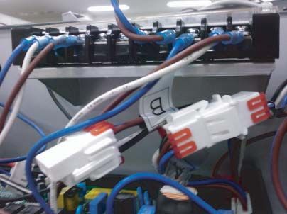
2 Terminal blocks The terminal blocks allow easy connection of field wiring
3 Unit ELB The ELB protects the unit against overload or short circuit
Water tank heater The ELB protects the water tank heater in sanitary water tank
4
ELB(optional) against overload or short circuit
5 Relays -
Relay
6 -
(optional for water tank heater)
7 Main PCB The main PCB(Printed Circuit Board) controls the functioning of the unit
8 Dry Contact Supporter Supporter to install Dry Contact (sold separately)
9 Magnet Contact
10 Unit MCCB The MCCB protects the unit against overload
Water tank heater The MCCB protects the water tank heater in sanitary water tank
11 against overload
MCCB(optional)
24 Air-to-Water Heat PumpGeneral Information
Control Panel
ENGLISH
14
1
2
1 3
0 4
2 8
3 9
4 10
5 11
6 12
7 13
Description
No Name
1 Display Panel
2 Change Temperature Button
3 Silent Mode On / Off Button
4 Operation Mode Selection Button
5 Water Heating Enable / Disable Button
6 ESC Button
7 Direction Button (Up, Down, Left, Right)
8 Power Button
9 Function Setting Button
10 Temperature Setting Mode Button
11 Temperature View Mode Button
12 Programming Button
13 Set / Clear button
14 Pressure gage
Wiring Diagram : Indoor Unit
- Refer to the wiring diagram inside the control box.
Circuit Diagram : Indoor Unit
- Refer to the circuit diagram inside the front panel.
Wiring Diagram : Outdoor Unit
- Refer to the attached wiring diagram in the outdoor unit.
Installation Manual 25General Information
Wiring Diagram : Indoor and Outdoor Unit(Including Field wiring)
(Indoor : Electric Heater 1Ø, Outdoor : 1Ø)
50Hz
230V
1~
26 Air-to-Water Heat PumpGeneral Information
Wiring Diagram : Indoor and Outdoor Unit(Including Field wiring)
(Indoor : Electric Heater 3Ø, Outdoor : 1Ø)
ENGLISH
MCCB
380V
220V
50Hz
50Hz
3~
3~
or
MCCB
M/C
3
M/C
230V
50Hz
M/C
1~
Installation Manual 27General Information
Wiring Diagram : Indoor and Outdoor Unit(Including Field wiring)
(Indoor : Electric Heater 3Ø 220V, Outdoor : 3Ø)
MCCB
220V
50Hz
3~
MCCB
M/C
3
220V
50Hz
1~
M/C
380V
50Hz
3~
M/C
28 Air-to-Water Heat PumpGeneral Information
Wiring Diagram : Indoor and Outdoor Unit(Including Field wiring)
(Indoor : Electric Heater 3Ø 380-415V, Outdoor : 3Ø)
ENGLISH
MCCB
M/C
220V
50Hz
1~
MCCB
3
M/C
M/C
380V
50Hz
3~
Installation Manual 29Installation of Outdoor Unit
3. Installation of Outdoor Unit
The outdoor unit of is installed outside to exchange heat with ambient air. Therefore, it
is important to secure proper space around the outdoor unit and care for specific external conditions.
This chapter presents a guide to install the outdoor unit, make a route to connect with the indoor, and
what to do when installed around seaside.
Conditions where Outdoor Unit is Installed
• If a sunroof is built over the unit to prevent Su
direct sunlight or rain exposure, make sure that nro
heat radiation from the heat exchanger is not
of
restricted.
300
• Ensure that the spaces indicated by arrows
around front, back and side of the unit.
• Do not place animals and plants in the path of
the warm air. Fe
• Take the weight of the outdoor unit into account ob nce
sta or
and select a place where noise and vibration cle 300
s
are minimum. 600
• Select a place so that the warm air and noise 700
from the outdoor unit do not disturb neighbors.
Minimum service space (unit:mm)
Drill a Hole in the Wall
• If making a hole to the wall is required to
connect pipe between the indoor unit and the Wall
outdoor unit, please follow below descriptions. Indoor Outdoor
- Drill the piping hole with a ø70mm hole core
drill.
- Piping hole should be slightly slant to the
5~7mm
outdoor side to prevent raindrop into indoor
side.
30 Air-to-Water Heat PumpInstallation of Outdoor Unit
Installation at Seaside
CAUTION
ENGLISH
1. Air conditioners should not be installed in areas where corrosive gases, such as acid or alkaline gas, are produced.
2. Do not install the product where it could be exposed to sea wind (salty wind) directly. It can result corrosion
on the product. Corrosion, particularly on the condenser and evaporator fins, could cause product malfunc-
tion or inefficient performance.
3. If outdoor unit is installed close to the seaside, it should avoid direct exposure to the sea wind. Otherwise it
needs additional anticorrosion treatment on the heat exchanger.
Selecting the location(Outdoor Unit)
1) If the outdoor unit is to be installed close to the seaside, direct exposure to the sea wind should be avoided.
Install the outdoor unit on the opposite side of the sea wind direction.
Sea wind Sea wind
2) In case, to install the outdoor unit on the seaside, set up a windbreak not to be exposed to the sea wind.
Windbreak • It should be strong enough like concrete to prevent
the sea wind from the sea.
• The height and width should be more than 150% of
the outdoor unit.
Sea wind
• It should be keep more than 700 mm of space
between outdoor unit and the windbreak for easy
air flow.
3) Select a well-drained place.
1. If you can’t meet above guide line in the seaside installation, please contact LG Electronics for the additional anticorrosion treatment.
2. Periodic ( more than once/year ) cleaning of the dust or salt particles stuck on the heat exchanger by using water
Seasonal wind and cautions in winter
• Sufficient measures are required in a snow area or severe cold area in winter so that product can be operated well.
• Get ready for seasonal wind or snow in winter even in other areas.
• Install a suction and discharge duct not to let in snow or rain.
• Install the outdoor unit not to come in contact with snow directly. If snow piles up and freezes on the air suction hole,
the system may malfunction. If it is installed at snowy area, attach the hood to the system.
• Install the outdoor unit at the higher installation console by 500 mm than the average snowfall (annual average
snowfall) if it is installed at the area with much snowfall.
• Where snow accumulated on the upper part of the Outdoor Unit by more than 100 mm, always remove snow for
operation.
1. The height of H frame must be more than 2 times the snowfall and its width shall not exceed the width of the
product. (If width of the frame is wider than that of the product, snow may accumulate)
2. Don't install the suction hole and discharge hole of the Outdoor Unit facing the seasonal wind.
Installation Manual 31Installation of Indoor Unit
4. Installation of Indoor Unit
The indoor unit of is installed inside where terminal of under floor water pipe cycle and
refrigerant pipe from the outdoor unit are accessible at the same time.
In this chapter conditions for installation place is described. In addition, considerations when
installing accessories or 3rd party accessories are described, too.
Conditions where Indoor Unit is Installed
Specific conditions are required for installation place such as service space, wall mounting, water
pipe length and height, total volume of water, adjusting expansion vessel, and water quality.
General Considerations
Followings are should be considered before the installation of the indoor unit.
- The installation place should be free from outdoor weather conditions such as rain, snow, wind,
frost, etc.
- Choose the place where is water-resistant or good drainage.
- Service space should be secured.
- No flammable materials around the indoor unit.
- Mice can not be appeared to prevent entering the indoor unit or attacking wires.
- Do not place anything in front of the indoor unit to ensure air circulation around the indoor unit.
- Do not locate anything under the indoor unit to be free from unexpected water out.
- In case of water pressure increasing to 3 bar, water drainage should be treated when water is
drained by safety valve.
Service Space
• Ensure that the spaces indicated by arrows around bottom,
250
side, and top side.
• Wider spaces are preferred for easy maintenance and
piping.
• If minimum service space is not secured, air circulation can
be troubled and internal parts of the indoor unit can be
damaged by overheating.
200 200
1300
Minimum service space
(unit : mm)
32 Air-to-Water Heat PumpInstallation of Indoor Unit
Mounting to Wall
Step 1. After releasing eight screws, detach front cover from the indoor unit. While detaching the
front cover, grab the carrying handles at left and right sides of the front cover. Then pull into
ENGLISH
upward direction. When assemble the front cover, remove detached side brackets of the
front cover and ONLY tighten two screws of bottom.
Bottom
screws
Remove
Step 2. Attach "Installation Sheet" to the wall and mark
the location of bolts. This sheet helps to find
correct location to the bolts.
The sheet should be attached level. If not, the supporting plate and the indoor unit will not be mounted
correctly.
Step 3. Detach the Installation sheet. Screw bolts with
supporting plate at the hole marks on the wall. (Ha
ll m
When screwing bolts, use M8 ~ M11 anchor ark
s)
bolts to secure hanging the indoor unit.
Eight small holes around four large hole marks can be used as
alternatives of M8 ~ M11 anchor bolts. But M8 ~ M11 anchor bolts are
more preferred.
Step 4. Hang the indoor unit at the supporting plate.
Also, catch the carrying handles at left and
right sides of the indoor unit.
While lifting the indoor unit, at least two persons
should be joined. Weight of the indoor unit is almost
55kg.
Installation Manual 33Installation of Indoor Unit
Water Volume and Pump Capacity
has different internal water pump according to the product capacity.
The water pump is three speed-adjustable (Maximum / Medium / Minimum), so it may be required to
change default water pump speed in case of noise by water flow. In most case, however, it is
strongly recommended to set speed as Maximum.
Water pump speed
To secure enough water flow rate, do not set water pump speed as ʻMin.ʼ It can lead unexpected flow
rate error CH14.
Product Heating Capacity : 9kW
8.0
7.5
7.0
6.5
6.0
aulic Head Loss(mH2O)
5.5
5.0
4.5
4.0
3.5
3.0
2.5
2.0
Med.
1.5
Max.
1.0
12
0.5
0.0
0 10 20 30 40 50 60 70 80 90 100 110
Water Flowrate(l/min)
Product Heating Capacity : 12kW,14kW,16kW
8.0
7.5
7.0
6.5
6.0
5.5
Hydraulic Head Loss(mH2O)
5.0
4.5
Max.
4.0
3.5
Med.
3.0
2.5
2.0
1.5
15
1.0
0.5
0.0
0 10 20 30 40 50 60 70 80 90 100 110
Water Flowrate(l/min)
Max. : high speed setting
Med. : low speed setting
Warning : Selecting a water flowrate outside the curves can cause damage to or malfunction of the unit.
: Operation cutoff range
34 Air-to-Water Heat PumpInstallation of Indoor Unit
Water Volume and Expansion Vessel Pressure
Inside expansion vessel is included which is 8 liter capacity with 1 bar pre-pressure.
ENGLISH
That means, according to the volume-pressure graph, total water volume of 230 liter is supported as
default. If total water volume is changed because of installation condition, the pre-pressure should be
adjusted to secure proper operation.
- Minimum total water volume is 20 liter.
- Pre-pressure is adjusted by the total water volume. If the indoor unit is located at the highest
position of the water circuit, adjustment is not required.
- To adjust pre-pressure, use nitrogen gas by certificated installer.
2.4
Pre-pressure in Expansion vessel (bar)
2.1
1.7
1.4
1.0
0.7
0.3
20 60 100 140 180 220 260 300 340
Maximum total water volume (liter)
Adjusting pre-pressure of expansion vessel is as following :
Step 1. Refer "Volume-Height" table.
If installation scene is belong to Case A, go to Step 2.
Otherwise, if it is Case B, do nothing. (pre-pressure adjustment is not required.)
Otherwise, if it is Case C, go to Step 3.
Step 2. Adjust pre-pressure by following equation.
Pre-pressure [bar] = (0.1xH+0.3) [bar]
where H : difference between indoor unit and the highest water pipe
0.3 : minimum water pressure to secure product operation
Step 3. Volume of expansion vessel is less than installation scene.
Please install additional expansion vessel at the external water circuit.
Volume-Height Table
V < 230 liter V ≥ 230 liter
H < 7m Case B Case A
H ≥ 7m Case A Case C
H : difference between indoor unit and the highest water pipe
V : total water volume of installation scene
Installation Manual 35Installation of Indoor Unit
Water Quality
Water quality should be complied with EN 98/83 EC Directives. Requirement for resolved chemical
ingredients is following table. Detailed water quality condition can be found in EN 98/83 EC
Directives.
Parameter Value Parameter Value
Acrylamide 0.10 μg/l Fluoride 1.5 mg/l
Antimony 5.0 μg/l Lead 10 μg/l
Arsenic 10 μg/l Mercury 1.0 μg/l
Benzene 1.0 μg/l Nickel 20 μg/l
Benzo(a)pyrene 0.010 μg/l Nitrate 50 mg/l
Boron 1.0 mg/l Nitrite 0.50 mg/l
Bromate 10 μg/l Pesticides 0.10 μg/l
Cadmium 5.0 μg/l Pesticides — Total 0.50 μg/l
Chromium 50 μg/l Polycyclic aromatic hydrocarbons 0.10 μg/l
Copper 2.0 mg/l Selenium 10 μg/l
Cyanide 50 μg/l Tetrachloroethene and Trichloroethene 10 μg/l
1.2-dichloroethane 3.0 μg/l Trihalomethanes — Total 100 μg/l
Epichlorohydrin 0.10 μg/l Vinyl chloride 0.50 μg/l
• If the product is installed at existing hydraulic water loop, it is important to clean hydraulic pipes to
remove sludge and scale.
• Installing sludge strainer in the water loop is very important to prevent performance degrade.
• Chemical treatment to prevent rust should be performed by installer.
36 Air-to-Water Heat PumpInstallation of Indoor Unit
Conditions if Accessories are Installed
This section describes conditions about installation place where accessories are installed. Detailed
ENGLISH
installation for accessories (including supported accessory specification, wiring, PCB setting for
accessory configuration, etc) will be dealt in separated chapter.
Thermostat
1. NEVER USE 230V AC Thermostat and 24V AC Thermostat at the same time. If used together, it
causes short-circuit and yields power cut-off by circuit breaker.
2. Some electro-mechanical type thermostat has internal delay time to protect compressor. In that case,
mode change can takes time more than user's expectation. Please read thermostat manual carefully
if the product does not response quickly.
3. Setting temperature range by thermostat can be different with that of the product. The heating or
cooling set temperature should be chosen within the setting temperature range of the product.
4. It is highly recommended that the thermostat should be installed where space heating is mainly
applied.
Following location should be avoid to secure proper operation :
• Height from floor is approximately 1.5 m.
• Thermostat can not be located where the area may be hidden when door is open.
• Thermostat can not be located where external thermal influence may be applied. (such as
above heating radiator or open window)
Remote Air Temperature Sensor
Role and constraint while installation of remote air temperature sensor is very similar to that of
thermostat.
• Distance between the indoor unit and the remote air temperature sensor should be less than 15 m
due to length of the connection cable of remote air temperature sensor.
• For other constraints, please refer to previous page where constraints about thermostat is
described
Direct
Sun ray contact area
Direct
yes Sun ray contact area
yes
no
no
no no
5ft 5ft
Connection cable (1.5m)
(1.5m) (less than 15m)
no
no
Thermostat Remote Air Temperature Sensor
Installation Manual 37You can also read