Dryer Products Liquid Separators, Drain Valves, & Refrigeration Dryers Catalog 603
←
→
Page content transcription
If your browser does not render page correctly, please read the page content below
(Revised 05-01-2012)

Dryer Products
Liquid Separators, Drain Valves, & Refrigeration Dryers
Catalog 603

the total systems approach to air preparation
Catalog 603                                                               Air Preparation Systems
Warning, Offer of Sale

    !    CAUTION:
  Polycarbonate bowls, being transparent and tough, are ideal for use with Filters and Lubricators. They are suitable for use in normal industrial
  environments, but should not be located in areas where they could be subjected to direct sunlight, an impact blow, nor temperatures outside
  of the rated range. As with most plastics, some chemicals can cause damage. Polycarbonate bowls should not be exposed to chlorinated
  hydro-carbons, ketones, esters and certain alcohols. They should not be used in air systems where compressors are lubricated with fire-
  resistant fluids such as phosphate ester and di-ester types.
  Metal bowls are recommended where ambient and/or media conditions are not compatible with polycarbonate bowls. Metal bowls resist
  the action of most such solvents, but should not be used where strong acids or bases are present or in salt laden atmospheres. Consult
  the factory for specific recommendations where these conditions exist.
  TO CLEAN POLYCARBONATE BOWLS USE MILD SOAP AND WATER ONLY! DO NOT use cleansing agents such as acetone, benzene,
  carbon tetrachloride, gasoline, toluene, etc., which are damaging to this plastic.
  Metal bowl guards are recommended for all applications.


                                                            ! WARNING
 FAILURE OR IMPROPER SELECTION OR IMPROPER USE OF THE PRODUCTS AND/OR SYSTEMS DESCRIBED HEREIN
 OR RELATED ITEMS CAN CAUSE DEATH, PERSONAL INJURY AND PROPERTY DAMAGE.
 This document and other information from The Company, its subsidiaries and authorized distributors provide product and/or
 system options for further investigation by users having technical expertise. It is important that you analyze all aspects of your
 application including consequences of any failure, and review the information concerning the product or system in the current
 product catalog. Due to the variety of operating conditions and applications for these products or systems, the user, through
 its own analysis and testing, is solely responsible for making the final selection of the products and systems and assuring that
 all performance, safety and warning requirements of the application are met.
 The products described herein, including without limitation, product features, specifications, designs, availability and pricing,
 are subject to change by The Company and its subsidiaries at any time without notice.

                                                             Offer of Sale
 The items described in this document are hereby offered for sale by The Company, its subsidiaries or its authorized
 distributors. This offer and its acceptance are governed by the provisions stated on the separate page of this document entitled
 “Offer of Sale”.

© Copyright 2008 Parker Hannifin Corporation. All Rights Reserved.

                                                                                                               Pneumatic Division
                                                                                                               Richland, Michigan
                                                                                                               www.wilkersoncorp.com
Catalog 603                                                            Air Preparation Systems
Table of Contents

Sources of Contamination........................................................................................................ 2-4
Purification Technologies..............................................................................................................5
Quality Standards.........................................................................................................................6
Purity Levels.................................................................................................................................7
WSA / WSO Liquid Separators............................................................................................... 8-10
Automatic Electrical Drain Valve – WDV3-G...............................................................................11
Zero Loss Drain – WDV2............................................................................................................12
WDRD Refrigeration Dryers................................................................................................. 13-17
Safety Guide......................................................................................................................... 18-19
Offer of Sale...............................................................................................................................20

             the total systems approach to air preparation

                                                                      1                                    Pneumatic Division
                                                                                                           Richland, Michigan
                                                                                                           www.wilkersoncorp.com
Catalog 603                                              Air Preparation Systems
Sources of Contamination

Compressed Air and its Purification from Generation to Application
Compressed air is an essential power source                  in the distribution system, it ensures that only
that is widely used throughout industry. This                the most critical areas receive air treated to the
safe, powerful and reliable utility can be the               highest level.
most important part of your production process.              In many instances the compressed air system will
However, your compressed air will contain water,             be supplying air to more than one application and
dirt, wear particles and even degraded lubricating           although the purification equipment specified in
oil which all mix together to form an unwanted               the compressor room would remain unchanged,
condensate. This condensate often acidic, rapidly            the point of use protection will vary depending
wears tools and pneumatic machinery, blocks                  upon the air quality requirements of each
valves and orifices causing high maintenance and             application.
costly air leaks. It also corrodes piping systems
                                                             In many cases this action alone is not enough,
and can bring your production process to an
                                                             as modern production systems and processes
extremely expensive standstill!
                                                             demand an even higher level of air quality. Where
The quality of air required throughout a typical             required, “point of use” filtration, refrigeration or
compressed air system can vary.                              desiccant air dryers can provide the correct air
It is highly recommended that the compressed air             quality, without the need for drying the complete
is treated prior to entry into the distribution system       compressed air installation, which can be both
as well as at each usage point or application.               costly and totally unnecessary.
This approach to system design provides the
most cost effective solution to system purification
as it not only removes the contamination already

Sources of Contamination Found in a Compressed Air System
Contaminants in a compressed air system can generally be attributed to the following:
The quality of air being drawn into the compressor
Air compressors draw in a large volume of air from the surrounding atmosphere containing large
numbers of airborne contaminants.
The type and operation of the air compressor
The air compressor itself can also add contamination, from wear particles to coolants and lubricants.
Compressed air storage devices and distribution systems
The air receiver and system piping are designed to store and distribute the compressed air. As
a consequence, they will also store the large amounts of contaminants drawn into the system.
Additionally, piping and air receivers will also cool the moist compressed air forming condensate which
causes damage and corrosion.

                                                         2                             Pneumatic Division
                                                                                       Richland, Michigan
                                                                                       www.wilkersoncorp.com
Catalog 603                                           Air Preparation Systems
Sources of Contamination

Types of Contamination Found in a Compressed Air System
Atmospheric Dirt                                          Rust and Pipescale
Atmospheric air in an industrial environment              Rust and pipescale can be found in air receivers
typically contains 140 million dirt particles for         and the piping of “wet systems” (systems without
every cubic meter of air. 80% of these particles          adequate purification equipment) or systems
are less than 2 microns in size and are too small         which were operated “wet” prior to purification
to be captured by the compressor intake filter,           being installed. Over time, this contamination
therefore passing directly into the compressed air        breaks away to cause damage or blockage in
system.                                                   production which can also contaminate final
                                                          product and processes.
Water Vapor, Condensed Water and Water                    Micro-organisms
Aerosols                                                  Bacteria and viruses will also be drawn into the
Atmospheric air contains water vapor (water               compressed air system through the compressor
in a gaseous form). The ability of compressed             intake and warm, moist air provides an ideal
air to hold water vapor is dependent upon                 environment for the growth of micro-organisms.
it's temperature. The higher the temperature,             Ambient air can typically contain up to 3,850
the more water vapor that can be held by the              micro-organisms per cubic meter. If only a
air. During compression, the air temperature              few micro-organisms were to enter a clean
is increased significantly, which allows it to            environment, a sterile process or production
easily retain the incoming moisture. After the            system, enormous damage could be caused that
compression stage, air is normally cooled to a            not only diminishes product quality, but may even
usable temperature. This reduces the airs ability         render a product entirely unfit for use and subject
to retain water vapor, resulting in a proportion of       to recall.
the water vapor being condensed into liquid water
which is removed by a condensate drain fitted             Liquid Oil and Oil Aerosols
to the compressor after-cooler. The air leaving           Most air compressors use oil in the compression
the after-cooler is now 100% saturated with               stage for sealing, lubrication and cooling. During
water vapor and any further cooling of the air will       operation, lubricating oil is carried over into the
result in more water vapor condensing into liquid         compressed air system as liquid oil and aerosols.
water. Condensation occurs at various stages              This oil mixes with water vapor in the air and
throughout the system as the air is cooled further        is often very acidic, causing damage to the
by the air receiver, piping and the expansion             compressed air storage and distribution system,
of valves, cylinders, tools and machinery. The            production equipment and final product.
condensed water and water aerosols cause
corrosion to the storage and distribution system,
damage production equipment and the end                   Oil Vapor
product. It also reduces production efficiency and        In addition to dirt and water vapor, atmospheric
increases maintenance costs. Water in any form            air also contains oil in the form of unburned
must be removed to enable the system to run               hydrocarbons. The unburned hydrocarbons drawn
correctly and efficiently.                                into the compressor intake as well as vaporized
                                                          oil from the compression stage of a lubricated
                                                          compressor will carry over into a compressed air
                                                          system where it can cool and condense, causing
                                                          the same contamination issues as liquid oil.
                                                          Typical oil vapor concentrations can vary between
                                                          0.05 and 0.5mg per cubic meter of air.

                                                      3                            Pneumatic Division
                                                                                   Richland, Michigan
                                                                                   www.wilkersoncorp.com
Catalog 603                                           Air Preparation Systems
Sources of Contamination

Up to 99% of the total liquid contamination found in a
compressed air system is water.
Oil is perceived to cause the most problems as it is seen emanating from open drain points and
exhausting valves, however, in the majority of instances, it is actually oily condensate (oil mixed with
water) that is being observed.

How Much Water Can Be Found In A Typical Compressed Air System?
The amount of water in a compressed air system is staggering. A small 100 cfm (2.8m3/min)
compressor and refrigeration dryer combination, operating for 4,000 hours in typical climatic conditions
can produce approximately 10,000 liters or 2,200 gallons of liquid condensate per year.
If the compressor is oil lubricated with a typical 2ppm (2 mg/m3) oil carryover, then although the
resulting condensate would visually resemble oil, oil would in fact account for less than 0.1% of the
overall volume and it is this resemblance to oil to which a false association is made.
The example above assumes uses a small compressor to highlight the large volume of condensate
produced. If a compressed air system was operated in warmer, more humid climates, or with
larger compressors installed, running for longer periods, the volume of condensate would increase
significantly.

Contamination and Types of
Compressor
It is often believed that the level of compressed
air purification equipment required in a system
is dependent upon the type of compressor used.
Contamination in a compressed air system
originates from many sources and is not related
solely to the compressor or it's lubricants.
No matter what compressor type is selected,
adequate filtration and separation products will
be required to remove the large volume of dirty
contaminated water as well as the dirt, rust,
pipescale and microbiological contamination in
the system.

Preventative Maintenance
Provides You With The Following
Benefits:
n   Lowest Operating Costs
n   Superior Compressed Air Quality
n   Continued Protection Of Downstream
    Equipment and Processes
n   Peace Of Mind

                                                     4                           Pneumatic Division
                                                                                 Richland, Michigan
                                                                                 www.wilkersoncorp.com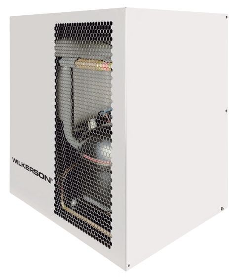
Catalog 603                                               Air Preparation Systems
Purification Technologies

Compressed Air and It's                                       (-40°C) to -100°F (-70°C) respectively (the actual
                                                              air temperature after an adsorption dryer is not
Purification                                                  the same as it's dewpoint).
Having identified the different types of                      Beneficially, a pressure dewpoint of -15°F (-26°C)
contamination that can be found within a                      or better will not only prevent corrosion, but will
compressed air system, we can now examine the                 also inhibit the growth of microorganisms within
purification technologies available for it's removal.         the compressed air system.

Particle and Coalescing Filters                               Refrigeration Dryers
Coalescing filters are probably the most important            Refrigeration dryers work by cooling the air, so
items of purification equipment in any compressed             are limited to positive pressure dewpoint ratings
air system. They are designed to remove oil                   to prevent freezing of the condensed liquid. Ideal
and water aerosols using mechanical filtration                for general purpose applications, they typically
techniques and have the additional benefit of                 provide pressure dewpoints of 38°F (3°C), 45°F
removing solid particulate to very low levels (as             (7°C) or 50°F (10°C) pdp. Air is reheated before
small as 0.01micron in size). Installed in pairs,             it re-enters the system to prevent piping from
most users believe one to be an oil removal filter            “sweating” in humid conditions. Refrigeration
and the other to be a particulate filter, when in             dryers are not suitable for installations where
fact, the pair of filters both perform the same               piping is installed in ambient temperatures below
function. The first filter, a general purpose filter is       the dryer dewpoint i.e. systems with external
used to protect the high efficiency filter against            piping.
bulk contamination. This "dual filter" installation
ensures a continuous supply of high quality
compressed air with low operational costs and                 Important Note Regarding
minimal maintenance time.                                     Compressed Air Dryers
                                                              As adsorption and refrigeration dryers are
Bulk Liquid Removal                                           designed to remove only water vapor and not
High Efficiency Water Separators                              water in a liquid form, they require the use of
                                                              coalescing filters and possibly a bulk liquid
Used to protect filters in systems where excessive            separator to work efficiently.
cooling takes place in distribution piping. Water
Separators will remove in excess of 98% of
bulk liquid contamination through centrifugal
separation techniques.

Adsorption (Desiccant) Dryers
Water vapor is water in a gaseous form and is
removed from compressed air using a dryer, with
dryer performance being measured as pressure
dewpoint. Adsorption or desiccant dryers remove
moisture by passing air over a regenerative
adsorbent material which strips the moisture from
the air. This type of dryer is extremely efficient
and typical pressure dewpoint ratings are -40°F
(-40°C) or -100°F (-70°C) pdp. This means that                NOTE:
for water vapor to condense into a liquid, the air            For Product Ordering & Specifications, Please
temperature would have to drop below -40°F                    Reference: Wilkerson 9EM-TK-190 Catalog

                                                          5                            Pneumatic Division
                                                                                       Richland, Michigan
                                                                                       www.wilkersoncorp.com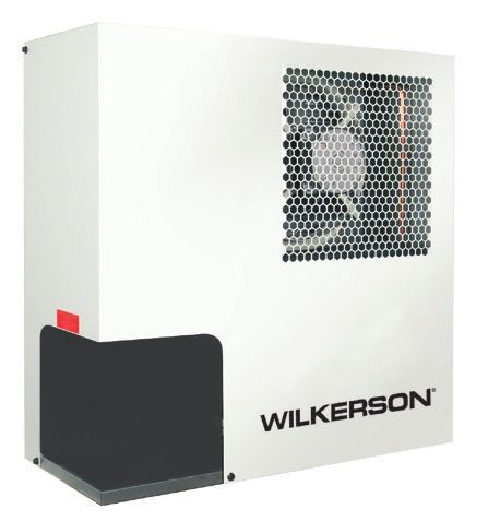
Catalog 603                                         (Revised 10/10/08)      Air Preparation Systems
Quality Standards

Compressed Air Quality Standards – ISO 8573
ISO 8573 is the group of International                ISO 8573.1 : 2001 is the primary                      Within ISO 8573.1 : 2001 purity levels
standards relating to the quality of                  document used from the ISO 8573                       for the main contaminants are shown
compressed air and consists of nine                   series and it is this document which                  in separate tables, however for ease of
separate parts. Part 1 specifies the                  allows the user to specify the air quality            use, this document combines all three
quality requirements of the compressed                or purity required at key points in a                 into one easy to understand table.
air and parts 2 - 9 specify the methods               compressed air system.
of testing for a range of contaminants.

                                      Solid Particulate                                             Water                            Oil
Purity
            Maximum number of particles per m 3           Particle Size Concentration         Vapor          Liquid Total oil (aerosol, liquid and vapor)
Class
         0.1 - 0.5 micron 0.5 - 1 micron 1 - 5 micron       micron        mg/m 3        Pressure Dewpoint g/m 3                 ppm (mg/m 3 )
   0            *               *               *              *             *                  *              *                      *
   1          100               1               0              —             —            -94°F (-70°C)        —                 0.008 (0.01)
   2        100,000           1,000            10              —             —            -40°F (-40°C)        —                  0.08 (0.1)
   3           —             10,000           500              —             —             -4°F (-20°C)        —                   0.83 (1)
   4           —               —             1,000             —             —             37°F (3°C)          —                   4.2 (5)
   5           —               —             20,000            —             —             45°F (7°C)          —                      —
   6           —               —               —               5             5             50F (10°C)          —                      —
   7           —               —               —               40            10                —               0.5                    —
   8           —               —               —               —             —                 —               5                      —
   9           —               —               —               —             —                 —               10                     —

* As specified by the equipment user or supplier.

Specifying Air Purity in Accordance
with ISO 8573.1 : 2001
When specifying the purity of air required, the standard must always be referenced, followed by the purity class selected for
each contaminant (a different purity class can be selected for each contaminant if required). An example of how to write an
air quality specification is shown below :

Example:
  ISO 8573.1 : 2001 Class 2.2.2                                                      than 1,000 particle in 0.5 to 1.0 micron size range is
  ISO8573.1 : 2001 refers to the standard document and its                           allowed in each cubic meter of compressed air, and 10
  revision, the three digits refer to the purity classifications                     particles in the 1.0 to 5.0 micron size range are allowed.
  selected for solid particulate, water and total oil. Selecting
                                                                                     Class 2, Water
  an air purity class of 2.2.2 would specify the following
                                                                                     A pressure dewpoint of -40°F (-40°C) or better is
  air quality when operating at the standard’s reference
                                                                                     required and no liquid water is allowed.
  conditions:
     Class 2, Particulate                                                            Class 2, Oil
     In each cubic meter of compressed air, not more than                            In each cubic Meter of compressed air, not more than
     100,000 particles in the 0.1 to 0.5 micron size range are                       0.1mg of oil is allowed. This is a combined level for both
     allowed in each cubic meter of compressed air, no more                          aerosol and oil vapor.

Cost Effective System Design
To achieve the stringent air quality levels required for today’s                 Point of use purification should also be employed, with
modern production facilities, a careful approach to system                       specific attention being focused on the application and the
design, commissioning and operation must be employed.                            level of air quality required. This approach to system design
Treatment at one point alone is not enough and it is highly                      ensures that air is not “over treated” and provides the most
recommended that the compressed air is treated prior to                          cost effective solution to high quality compressed air.
entry into the distribution system to a quality level suitable
for protecting air receivers and distribution piping.

                                                                            6                                        Pneumatic Division
                                                                                                                     Richland, Michigan
                                                                                                                     www.wilkersoncorp.com
Catalog 603                                                                Air Preparation Systems
Purity Level

ISO Class 2.4.2                                                                                               Good Purity Level

                  Compressor Room                           Air Preparation Equipment
          Air Preparation Equipment

                         100°F                                                                                     Dew Point
                         (38°C)                                                                                    40°F (4°C)

               Aftercooler
  Compressor                                                                         Refrigerated
                                                                                        Dryer
                                                          Particulate   Coalescing                                          Particulate   Coalescing
                                                            Filter        Filter                                              Filter        Filter
                                  Bulk Liquid
                                   Separator

ISO Class 2.2.2                                                                                             Better Purity Level
                               Compressor Room                              Point-Of-Use
                       Air Preparation Equipment                            Air Preparation Equipment

                                                                                                                                 Dew Point
                                          100°F                                                                                 -40°F (-40°C)

                                                                                                    Check
                               Aftercooler                                                          Valve
               Compressor

                                                                          Particulate Coalescing                        Coalescing
                                                                            Filter      Filter                            Filter
                                                  Bulk Liquid
                                                                                                            Desiccant
                                                   Separator
                                                                                                              Dryer

ISO Class 2.2.2                                                                                                 Best Purity Level
                                     Compressor Room                           Point-Of-Use
                             Air Preparation Equipment                         Air Preparation Equipment

                                                100°F                                                             Dew Point
                                                (38°C)                                                           -40°F (-40°C)

                                    Aftercooler
                 Compressor

                                                                              Particulate   Coalescing
                                                                                Filter        Filter   Regenerative
                                                                                                        Desiccant
                                                         Bulk Liquid
                                                                                                          Dryer
                                                          Separator

                                                                          7                                    Pneumatic Division
                                                                                                               Richland, Michigan
                                                                                                               www.wilkersoncorp.com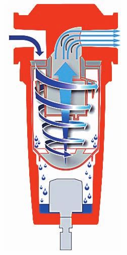
Catalog 603                                                     Air Preparation Systems
Liquid Separators                                               WSA / WSO Series

    Liquid Separators WSA / WSO

                                                                    Specifications
                                                                    Maximum Operating (WSA)                     200 PSIG (13.8 bar)
                                                                    Pressure          (WS0)                     232 PSIG (16.0 bar)
                                                                    Operating             (WSA)           32° to 150°F (0° to 65.5°C)
                                                                    Temperature           (WS0)           35° to 176°F (1.6° to 80°C)
                                                                    Pressure Differential at Rated Flow          1.0 PSID (0.07 bar)

                                                                    Materials of Construction
                                                                                                 WSA                          WS0
                                                                    Housing                      Zinc                     Aluminum
                                                                    Seals                       Nitrile                Fluorocarbon
Features
n   High Flow Rates
n   Less than 1 PSIG Differential Pressure                          Liquid Separators
n   Lightweight Cast Aluminum Housing with                          Our unique design combines the techniques of centrifugal
    1" to 3" NPT Connections (WS0)                                  action and other mechanical separation principles
                                                                    (Impingement, Separation, Laminar Flow and Stokes Law)
n   Cast Zinc Housings with 1/4" to 1" NPT                          to remove large quantities of liquid and solid contamination.
    Connections (WSA)                                               Typical applications include water separation downstream of
n   External Surfaces Epoxy Painted for Maximum                     aftercoolers, protection of refrigerant and heatless
                                                                    regenerative desiccant dryers, downstream of air receivers,
    Corrosion Protection
                                                                    and other liquid / gas separation duties where the volume of
n   Standard Equipped with Quick Disconnect                         water and solids poses a real problem.
    Bowls for Ease of Service (WSA)
n   Three (3) Optional Automatic Drains Available

 Model                                 In / Out              Rated Flow                Approx.                  Recommended
 Number                             NPT Pipe Conn.       (SCFM) @ 100 PSIG*           Weight lbs.               Automatic Drain
 WSA-02-M00**                            1/4"                    25                      2.2                        Optional
 WSA-02-FM0                              1/4"                    25                      2.2                        Internal
 WSA-03-M00**                            3/8"                    50                      2.6                        Optional
 WSA-03-FM0                              3/8"                    50                      2.6                        Internal
 WSA-04-M00**                            1/2"                    50                      2.6                        Optional
 WSA-04-FM0                              1/2"                    50                      2.6                        Internal
 WSA-06-M00**                            3/4"                   100                      6.0                        Optional
 WSA-06-FM0                              3/4"                   100                      6.0                        Internal
 WSA-08-M00**                             1"                    120                      6.0                        Optional
 WSA-08-FM0                               1"                    120                      6.0                        Internal
                                                                                                                 X02-04-FM0
 WS0-08-000B                                1"                  233                       4.8
                                                                                                                   WDV3-G
                                                                                                                  X02-04-FM0
 WS0-0B-000B                              1-1/2"                472                       11.2
                                                                                                                   WDV3-G
                                                                                                                 X02-04-FM0
 WS0-0C-000B                                2"                  742                      11.2
                                                                                                                   WDV3-G
                                                                                                                  X02-04-FM0
 WS0-0E-000B                                3"                  1700                     22.0
                                                                                                                   WDV3-G
*1 PSID maximum differential.   **Models have petcock.

                                                                8                                    Pneumatic Division
                                                                                                     Richland, Michigan
                                                                                                     www.wilkersoncorp.com
Catalog 603 Air Preparation Systems
Liquid Separators Operation WSA / WSO Series
Operation
n Air Enters the Water Separator Inlet and Turns
Into the Separator Module.
n The Inlet of the Separator Module Contains a
Set of Fixed Vanes Which the Air Must Pass
Through.
n The Vanes Force the Air to Spin Inside the
Vessel.
n The Spinning Air is Then Forced to Change
Direction as it Passes the Impinger.
n A Vortex is Created Which, Due to the
Design of the Separator Module, Narrows and
Intensifies as it Reaches the Lower Part of the
Vanes
Separator Module.
n Bulk Liquid is Removed From the Airstream
Impinger Due to:
• Directional Changes of the Airstream
• Velocity Changes
• Centrifugal Action of the Vortex
n As the Vortex Reaches the Bottom of the
Module, Air is Forced Through The Center of
the Vortex.
n Aerospace Turning Vanes, Located in the Outlet
of the Separator Module, Turn an Inefficient
Corner Into a Number of More Efficient Corners.
n Turning Vanes Reduce Turbulence, Minimizing
Pressure Loss and Cost of Ownership.
n The Number of Vanes Required is Dependent
Upon the Conduit Diameter.
9 Pneumatic Division
Richland, Michigan
www.wilkersoncorp.comCatalog 603 Air Preparation Systems
Liquid Separators WSA / WSO Series
A
B
A
CL Pipe
B
H CL Pipe
PRESS
TURN
PRESS
TURN
G E
E C
C
J D
X02
D = Bowl Removal Clearance Dimension
J = External Drain Discharge Port (NPT)
F D F D
(NPT) (NPT)
1.73 3.46
(44) (88)
WSA WS0
ON TEST OFF
4 6 10 20 30
2 8 5 40
0.5 0 10 0.6 ohm 45
4.53
(115)
NOTE: MAXIMUM separator efficiency of 98%+ is achieved
in the range of 15 to 100% of rated flow in SCFM. At flow
rates of 100%, separator efficiency is reduced
considerably. Consult your Wilkerson distributor or contact
Wilkerson for assistance in selecting the correct separator
Front View Side View model for your application.
WDV3-G
Model NPT NPT
Number A B C D E F G H J
WSA-02-M00* 3.00 .90 5.51 3.50 6.41 1/8 — — —
WSA-02-FM0 3.00 .90 5.51 3.50 6.41 1/8 — — —
WSA-03-M00* 3.35 .98 6.36 3.50 7.34 1/8 — — —
WSA-03-FM0 3.35 .98 6.36 3.50 7.34 1/8 — — —
WSA-04-M00* 3.35 .98 6.36 3.50 7.34 1/8 — — —
WSA-04-FM0 3.35 .98 6.36 3.50 7.34 1/8 — — —
WSA-06-M00* 4.62 1.00 9.00 3.50 10.00 1/8 — — —
WSA-06-FM0 4.62 1.00 9.00 3.50 10.00 1/8 — — —
WSA-08-M00* 4.62 1.00 9.00 3.50 10.00 1/8 — — —
WSA-08-FM0 4.62 1.00 9.00 3.50 10.00 1/8 — — —
WS0-08-000B 5.10 1.60 9.20 3.00 10.80 1/2 5.90 18.00 1/4
WDV3-G — — — — — — 1.73 13.83 —
WS0-0B-000B 6.70 2.00 15.00 4.00 17.00 1/2 5.90 18.00 1/4
WDV3-G — — — — — — 1.73 13.83 —
WS0-0C-000B 6.70 2.00 15.00 4.00 17.00 1/2 5.90 24.50 1/4
WDV3-G — — — — — — 1.73 20.33 —
WS0-0E-000B 8.10 2.40 17.50 4.72 19.90 1/2 5.90 28.90 1/4
WDV3-G — — — — — — 1.73 24.73 —
*Models have petcock.
10 Pneumatic Division
Richland, Michigan
www.wilkersoncorp.comCatalog 603 (Revised 10/10/08) Air Preparation Systems
Automatic Electrical Drain Valve WDV3 Series
Automatic Electrical Drain Valve – WDV3-G
Specifications
Operating Pressure................................ 230 PSIG (15,9 bar)
Ambient Operating Range Temperature:
34° to 130°F (1.1° to 54°C)
Coil Insulation
Class H........................................................340°F (171.1°C)
Voltages
AC.................................................................115, 230/50-60
Timer:
Open Time.................................... .5 to 10 sec., Adjustable
Cycle Time.................................... .5 to 45 min., Adjustable
Maximum Current Rating......................................4mA Max.
WDV3-G
Port Size...................................................... 1/4, 3/8, 1/2 NPT
The WDV3 Electrical Drain is designed to remove
Weight.............................................................. 1.8 lb. (0.8 kg)
condensate from compressors, compressed air dryers and
receivers up to any size, type or manufacturer.
The WDV3 offers true installation simplicity and it is
recognized as the most reliable and best performing Materials of Construction
condensate drain worldwide. The large orifice in the direct Valve Body..........................................Brass / Stainless Steel
acting valve, combined with its sophisticated timer module
ensure many years of trouble-free draining of condensate. Enclosure (IP65 / NEMA 4)................................. ABS Plastic
Internal Parts .....................................Brass / Stainless Steel
Benefits Valve Seals............................................. FPM (Fluorocarbon)
n Does Not Air-Lock During Operation.
n Compressed Air Systems Up to Any Size.
n Also Available In Stainless Steel.
n The Direct Acting Valve Is Serviceable.
n Suitable for All Types of Compressors.
n TEST (Micro-Switch) Feature.
n High Time Cycle Accuracy.
n Large (4.5mm) Valve Orifice. A C
Ordering Information
ON TEST OFF
4 6 10 20 30
2 8 5 40
0.5 0 10 0.6 ohm 45
Pipe Valve
Family Voltage Size Material Pressure
B
WDV3 – G 1 2 B L
Family Pressure
G General L 230 PSIG
(16 bar)
Voltage Valve Material Model Selection and Dimensions
1 120V AC B Brass Model
Pipe Size A B C
2 230V AC
2 1/4" General Number
3 3/8" General 1.73 4.53 3.46
4 1/2" General WDV3-G**BL
(44) (115) (88)
11 Pneumatic Division
Richland, Michigan
www.wilkersoncorp.comCatalog 603 Air Preparation Systems
Zero Loss Drain WDV2 Series
Zero Loss Drain – WDV2
Specifications
Drain Volume..........................................0.01 Gallons / Cycle
Maximum Fluid Temperature...........................150°F (60°C)
Voltage.................................................110 to 240V, 50/60 Hz
Inlet Ports (2)........................................................... 1/2" NPT
Outlet Ports (1)................................... 5/16" (8mm) I.D. Hose
Operating Conditions
Ambient Temperature....................33° to 140°F (0° to 60°C)
Maximum Operating Pressure................. 232 PSIG (16 bar)
WDV2-425 The WDV2 Electronic Demand Drain Valves, with zero air
loss, are suitable for all compressed air system applications
Features from aftercoolers to filters to receivers to refrigerated dryers.
n Zero Air Loss. These drain valves activate automatically and are both
reliable and economical.
n Automatically Self-Adjusting for Voltages
from 110 to 230V. Alarm Mode
n Sensor Device with No Moving Parts. Should the drain fail to discharge due to an excessive
volume of condensate or blocked outlet piping, an alarm
n Sophisticated Electronic Controls.
condition is activated. During the alarm condition, the drain
n Alarm with Remote Contacts. cycles continuously in an attempt to remove the excess
n Large Inlet Port to Eliminate Clogging. condensate. At the same time, the volt free alarm contacts
change state and the normally green power LED flashes to
n Manual Push-to-Test Button. indicate a problem. When the excess condensate or
n Automatically Clears Slugs. blockage has been cleared, the drain will resume normal
operation.
Benefits Operation
n Energy Efficient. 1. Upon power up, the outlet 2. When condensate is
valve is closed and sensor detected by the sensor, the
n World-Wide Applications.
is constantly monitoring for outlet valve is opened for a
n Long Life. presence of liquid. pre-set time.
n High Reliability.
n Versatility, Early Warning.
n Low Maintenance.
n On Demand Operation.
n Maintenance Free.
3. The condensate is 4. The outlet valve is closed
B
discharged from the outlet after a pre-set time has
port, due to the system expired. The opening time
pressure acting on the top has been calculated to
of the liquid. always ensure a small
C amount of liquid remains in
A
bowl. This liquid acts as a
seal, preventing air loss.
Model Selection and Dimensions
Model
A D C
Number
3.23 4.61 4.65
WDV2-425
(82) (117) (118) Level monitoring and discharge operation are continuous.
12 Pneumatic Division
Richland, Michigan
www.wilkersoncorp.comCatalog 603 Air Preparation Systems
Refrigeration Dryers WDRD Series
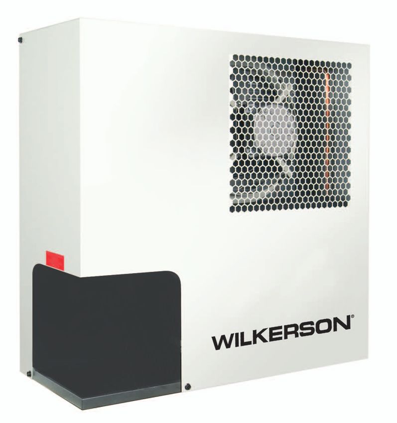
Refrigeration Dryers – WDRD
Key Features:
n “Plug & Play” Design for Easy Installation and
Operation (WDRD10 - WDRD125).
n Small Space Saving Design.
n Oversized Demister Separator Resulting in
Excellent Liquid Removal Over all Operating
Conditions.
n Low Pressure Differential Across The Dryer
(1.45 PSIG Average).
n Environmentally Friendly Refrigerant.
n Oversized Condenser to Operate in Ambients to
122°F (50°C).
n All Models Incorporate a Dewpoint Indicator.
WDRD10 - 175
Why Refrigeration Dryers?
Compressed air is an important provider of energy for industry; what is often overlooked however is the need to
provide quality treatment for this air. Compressed air contains condensate which, when cooled, will turn into water,
causing extensive damage to both the compressed air network and the finished product itself. WDRD refrigeration
dryers actively remove this condensate to achieve near perfectly dry compressed air. The benefits are notable:
less system downtime, reduced costs and maintenance, and an improved finished product. WDRD, thanks to its
PlusPack heat exchanger (patent pending) and the most compact dimensions on the market, will prove a major
asset in your factory.
Model Selection
Model Recommended
Pipe Size
Number Filtration†
WDRD10 1/2" NPT-F
WDRD15 1/2" NPT-F
F2804WDRD
WDRD25 1/2" NPT-F
WDRD35 1/2" NPT-F
WDRD50 3/4" NPT-F
WDRD75 3/4" NPT-F F2806WDRD
WDRD100 3/4" NPT-F
WDRD125 1-1/2" NPT-F
WDRD150 1-1/2" NPT-F F3908WDRD
WDRD175 1-1/2" NPT-F
† Consists of: Particle & Coalescing Filter Assembly with Mounting Bracket.
13 Pneumatic Division
Richland, Michigan
www.wilkersoncorp.comCatalog 603 Air Preparation Systems
Refrigeration Dryers WDRD Series
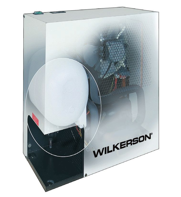
PlusPack Heat Exchanger Demister Separator
(patent pending) A high capacity demister separator is employed for the
removal of condensed liquids. This lowers the air velocity
The revolutionary PlusPack features a 3-in-1
which maximizes the condensate separation from the air,
aluminum design with integral air connections. All even when the dryer is not operating at maximum flow. This
models include an air-to-air freecooler, while the design also ensures the differential pressure across the
unique “slowflow” demister ensures perfect dewpoints dryer is kept to a minimum.
whatever the operating conditions.
Refrigerant Condenser Refrigerant Compressor
Oversized high efficiency air cooled condenser. Maintenance free hermetically sealed refrigerant
Re-positioned to improve reliability and reduce the risk of dirt compressor. Low refrigerant charge eliminates the
contamination. requirement for pre-heating on start up & prevents any liquid
refrigerant returns.
Condensate Drain Niche
The WDRD Refrigeration Dryer range comes standard Assured Quality & Performance
with a level sensing automatic float drain. Other drains are Every dryer undergoes sophisticated testing, including
available upon request. The positioning of the drain niche dewpoint tests with compressed air flow. Multiple helium
allows for easy access to the drain without the requirement leak testing, again on every dryer, ensures years of trouble-
of removing panels. free operation.
14 Pneumatic Division
Richland, Michigan
www.wilkersoncorp.comCatalog 603 Air Preparation Systems
Technical Specifications Refrigeration Dryers - WDRD Series
Energy Efficiency
Poorly constructed heat exchangers and liquid separators
create a high pressure differential across the dryer
which leads to high operational costs and poor dewpoint
performance.
The WDRD dryer range utilizes advanced heat exchanger
and demister separation technology and delivers
uncompromising performance at the lowest cost of
ownership.
Moisture Separation Technology
slowflow demister moisture removal
Separation Efficiency
centrifugal separator
demister separator
Air
The oversized “slowflow” demister is non-velocity sensitive
and therefore offers excellent liquid separation whatever the
airflow.
15 Pneumatic Division
Richland, Michigan
www.wilkersoncorp.comCatalog 603 (Revised 01/28/10) Air Preparation Systems
Technical Specifications Refrigeration Dryers - WDRD Series
Technical Information
Maximum Ambient Temperature........................... 122°F (50°C)
Maximum Inlet Temperature –
Models WDRD10 thru WDRD175:................. 149°F (65°C)
Minimum Ambient Temperature................................ 41°F (5°C)
Maximum Inlet Pressure –
Models WDRD10 thru WDRD175:.........232 PSIG (16 bar)
Refrigerant –
Models WDRD10 thru WDRD175:............................R134a
Nominal Flow*
Model Primary Recommended
Pipe Size
Number SCFM Nm3/hr Nm3/min Voltages Filtration†
WDRD10-115160 1/2" NPT-F 10 17 0.3 115V/1ph/60Hz
WDRD15-115160 1/2" NPT-F 15 26 0.4 115V/1ph/60Hz
F2804WDRD
WDRD25-115160 1/2" NPT-F 25 43 0.7 115V/1ph/60Hz
WDRD35-115160 1/2" NPT-F 35 60 1.0 115V/1ph/60Hz
WDRD50-115160 3/4" NPT-F 50 85 1.4 115V/1ph/60Hz
WDRD75-115160 3/4" NPT-F 75 127 2.1 115V/1ph/60Hz F2806WDRD
WDRD100-115160 3/4" NPT-F 100 170 2.8 115V/1ph/60Hz
WDRD125-115160 115V/1ph/60Hz &
1-1/2" NPT-F 125 212 3.5
WDRD125-230160 230V/1ph/60Hz
WDRD150-115160 115V/1ph/60Hz & F3908WDRD
1-1/2" NPT-F 150 255 4.2
WDRD150-230160 230V/1ph/60Hz
WDRD175-230160 1-1/2" NPT-F 175 297 5.0 230V/1ph/60Hz
† Consists of: Particle & Coalescing Filter Assembly with Mounting Bracket.
*Capacities are based upon:
Ambient Temperature..............................................................100°F (38°C)
Inlet Temperature................................................................... 100°F (38°C)
Working Pressure............................................................. 100 PSIG (7 bar)
16 Pneumatic Division
Richland, Michigan
www.wilkersoncorp.comCatalog 603 Air Preparation Systems
Technical Specifications Refrigeration Dryers - WDRD Series
Air Flow Correction Factors Using the correction factors from the tables:
Capacity correction factors to be used when operating Nominal Flow = 25 SCFM
conditions differ from those shown below. C1 = 1.09
To obtain dryer capacity at new conditions multiply nominal C2 = .67
capacity* x C1 x C2 x C3 C3 = 1.07
25 x 1.09 x .67 x 1.07 = 19.53 SCFM
Models WDRD10 - WDRD175 Or, our 25 SCFM capacity dryer, under these new
Ambient Temperature (C1) conditions, will have a new flow capacity of only 19.53
°F 60 70 80 90 100 110 120 SCFM. If we truly needed to flow 25 SCFM of air, we need
to adjust our selection to a bigger dryer.
°C 16 21 27 32 38 43 49
A WDRD35 would have a flow capacity of 27.35 SCFM,
Correction
1.34 1.26 1.17 1.09 1.00 0.91 0.82 making it the proper selection.
Factor
It is very important to understand the operating conditions
under which your refrigerated dryer will function, to make a
Inlet Temperature (C2)
selection that will give you the desired performance.
°F 90 100 110 120 140 149
°C 32 38 43 49 60 65
Correction
1.24 1.00 0.81 0.67 0.45 0.43
Factor
Working Pressure (C3)
PSIG 60 80 100 125 150 175 200 230
bar 4 6 7 9 10 12 14 16
Correction
0.83 0.93 1.00 1.07 1.12 1.13 1.19 1.22
Factor
*Capacities are based upon: B
Ambient Temperature..............................................................100°F (38°C)
Inlet Temperature................................................................... 100°F (38°C)
Working Pressure............................................................. 100 PSIG (7 bar)
Example: Using Air Flow Correction
Factors
The WDRD dryers on page 16 have been sized for the
following conditions with the stated flows listed in SCFM and
Nm3. A C
Ambient Temperature = 100° F
Inlet Temperature = 100° F
Working Pressure = 100 PSIG
Weights and Dimensions
However, many applications are not under these conditions, Dimensions
Model Inches (mm) Weight
so we need to understand the use of the “Air Flow Number lbs (Kg)
Correction Factors”. These factors allow you to adjust for A B C
changes in the ambient temperature, inlet temperature and
WDRD10 8.3 (210) 17 (430) 17,7 (450) 42 (19)
working pressure.
WDRD15 8.3 (210) 17 (430) 17.7 (450) 42 (19)
The formula is simple to use, new dryer capacity = nominal
dryer flow x C1 (correction factor for ambient temperature) x WDRD25 8.3 (210) 19.9 (505) 19.7 (500) 52 (24)
C2 (correction factor for inlet temperature) x C3 (correction WDRD35 8.3 (210) 19.9 (505) 19.7 (500) 52 (24)
factor for working pressure.
WDRD50 8.9 (225) 22.3 (565) 20.5 (520) 58 (27)
We have selected a WDRD25 for our initial dryer for
conditions of 100° F ambient temperature, 100° F inlet WDRD75 8.9 (225) 22.3 (565) 20.5 (520) 68 (31)
temperature and 100 PSIG working pressure. WDRD100 8.9 (225) 22.3 (565) 20.5 (520) 77 (35)
We find, however, that the applications’ conditions really are: WDRD125 16.7 (425) 23.8 (605) 21.8 (555) 115 (52)
Ambient Temperature = 90° F
WDRD150 16.7 (425) 23.8 (605) 21.8 (555) 128 (52)
Inlet Temperature = 120° F
Working Pressure = 125 PSIG WDRD175 16.7 (425) 23.8 (605) 21.8 (555) 132 (60)
17 Pneumatic Division
Richland, Michigan
www.wilkersoncorp.comCatalog 603 Air Preparation Systems
Safety Guidelines
Safety Guide For Selecting And Using Pneumatic Division
Products And Related Accessories
! WARNING:
FAILURE OR IMPROPER SELECTION OR IMPROPER USE OF PNEUMATIC DIVISION PRODUCTS,
ASSEMBLIES OR RELATED ITEMS (“PRODUCTS”) CAN CAUSE DEATH, PERSONAL INJURY, AND PROPERTY
DAMAGE. POSSIBLE CONSEQUENCES OF FAILURE OR IMPROPER SELECTION OR IMPROPER USE OF
THESE PRODUCTS INCLUDE BUT ARE NOT LIMITED TO:
• Unintended or mistimed cycling or motion of machine members or failure to cycle
• Work pieces or component parts being thrown off at high speeds.
• Failure of a device to function properly for example, failure to clamp or unclamp an associated item or device.
• Explosion
• Suddenly moving or falling objects.
• Release of toxic or otherwise injurious liquids or gasses.
Before selecting or using any of these Products, it is important that you read and follow the instructions below.
1. GENERAL INSTRUCTIONS
1.1. Scope: This safety guide is designed to cover general guidelines on the installation, use, and maintenance of Pneumatic Division
Valves, FRLs (Filters pressure Regulators and Lubricators), Vacuum products and related accessory components.
1.2. Fail-Safe: Valves, FRLs, Vacuum products and their related components can and do fail without warning for many reasons. Design
all systems and equipment in a fail-safe mode, so that failure of associated valves, FRLs or Vacuum products will not endanger
persons or property.
1.3. Distribution: Provide a copy of this safety guide to each person that is responsible for selection, installation, or use of Valves, FRLs
or Vacuum products. Do not select, or use Wilkerson valves, FRLs or vacuum products without thoroughly reading and
understanding this safety guide as well as the specific Wilkerson publications for the products considered or selected.
1.4. User Responsibility: Due to the wide variety of operating conditions and applications for valves, FRLs, and vacuum products
Wilkerson and its distributors do not represent or warrant that any particular valve, FRL or vacuum product is suitable for any specific
end use system. This safety guide does not analyze all technical parameters that must be considered in selecting a product. The
user, through its own analysis and testing, is solely responsible for:
• Making the final selection of the appropriate valve, FRL, Vacuum component, or accessory.
• Assuring that all user’s performance, endurance, maintenance, safety, and warning requirements are met and that the application
presents no health or safety hazards.
• Complying with all existing warning labels and / or providing all appropriate health and safety warnings on the equipment on
which the valves, FRLs or Vacuum products are used; and,
• Assuring compliance with all applicable government and industry standards.
1.5. Safety Devices: Safety devices should not be removed, or defeated.
1.6. Warning Labels: Warning labels should not be removed, painted over or otherwise obscured.
1.7. Additional Questions: Call the appropriate Wilkerson technical service department if you have any questions or require any
additional information. See the Wilkerson publication for the product being considered or used, or call 269-629-2550, or go to
www.wilkersoncorp.com, for telephone numbers of the appropriate technical service department.
2. PRODUCT SELECTION INSTRUCTIONS
2.1. Flow Rate: The flow rate requirements of a system are frequently the primary consideration when designing any pneumatic system.
System components need to be able to provide adequate flow and pressure for the desired application.
2.2. Pressure Rating: Never exceed the rated pressure of a product. Consult product labeling, Pneumatic Division catalogs or the
instruction sheets supplied for maximum pressure ratings.
2.3. Temperature Rating: Never exceed the temperature rating of a product. Excessive heat can shorten the life expectancy of a
product and result in complete product failure.
2.4. Environment: Many environmental conditions can affect the integrity and suitability of a product for a given application. Pneumatic
Division products are designed for use in general purpose industrial applications. If these products are to be used in unusual
circumstances such as direct sunlight and/or corrosive or caustic environments, such use can shorten the useful life and lead to
premature failure of a product.
2.5. Lubrication and Compressor Carryover: Some modern synthetic oils can and will attack nitrile seals. If there is any possibility of
synthetic oils or greases migrating into the pneumatic components check for compatibility with the seal materials used. Consult the
factory or product literature for materials of construction.
2.6. Polycarbonate Bowls and Sight Glasses: To avoid potential polycarbonate bowl failures:
• Do not locate polycarbonate bowls or sight glasses in areas where they could be subject to direct sunlight, impact blow, or
temperatures outside of the rated range.
• Do not expose or clean polycarbonate bowls with detergents, chlorinated hydro-carbons, keytones, esters or certain alcohols.
• Do not use polycarbonate bowls or sight glasses in air systems where compressors are lubricated with fire resistant fluids such as
phosphate ester and di-ester lubricants.
18 Pneumatic Division
Richland, Michigan
www.wilkersoncorp.comCatalog 603 Air Preparation Systems
Safety Guidelines
2.7. Chemical Compatibility: For more information on plastic component chemical compatibility see Pneumatic Division technical
bulletins Tec-3, Tec-4, and Tec-5
2.8. Product Rupture: Product rupture can cause death, serious personal injury, and property damage.
• Do not connect pressure regulators or other Pneumatic Division products to bottled gas cylinders.
• Do not exceed the maximum primary pressure rating of any pressure regulator or any system component.
• Consult product labeling or product literature for pressure rating limitations.
3. PRODUCT ASSEMBLY AND INSTALLATION INSTRUCTIONS
3.1. Component Inspection: Prior to assembly or installation a careful examination of the valves, FRLs or vacuum products must be
performed. All components must be checked for correct style, size, and catalog number. DO NOT use any component that displays
any signs of nonconformance.
3.2. Installation Instructions: Wilkerson published Installation Instructions must be followed for installation of Wilkerson valves, FRLs
and vacuum components. These instructions are provided with every Wilkerson valve or FRL sold, or by calling 269-629-2550, or at
www.wilkersoncorp.com.
3.3. Air Supply: The air supply or control medium supplied to Valves, FRLs and Vacuum components must be moisture-free if ambient
temperature can drop below freezing
4. VALVE AND FRL MAINTENANCE AND REPLACEMENT INSTRUCTIONS
4.1. Maintenance: Even with proper selection and installation, valve, FRL and vacuum products service life may be significantly reduced
without a continuing maintenance program. The severity of the application, risk potential from a component failure, and experience
with any known failures in the application or in similar applications should determine the frequency of inspections and the servicing or
replacement of Pneumatic Division products so that products are replaced before any failure occurs. A maintenance program must
be established and followed by the user and, at minimum, must include instructions 4.2 through 4.10.
4.2. Installation and Service Instructions: Before attempting to service or replace any worn or damaged parts consult the appropriate
Service Bulletin for the valve or FRL in question for the appropriate practices to service the unit in question. These Service and
Installation Instructions are provided with every Wilkerson valve and FRL sold, or are available by calling 269-629-2550, or by
accessing the Wilkerson web site at www.wilkersoncorp.com.
4.3. Lockout / Tagout Procedures: Be sure to follow all required lockout and tagout procedures when servicing equipment. For more
information see: OSHA Standard – 29 CFR, Part 1910.147, Appendix A, The Control of Hazardous Energy – (Lockout / Tagout)
4.4. Visual Inspection: Any of the following conditions requires immediate system shut down and replacement of worn or damaged
components:
• Air leakage: Look and listen to see if there are any signs of visual damage to any of the components in the system. Leakage is an
indication of worn or damaged components.
• Damaged or degraded components: Look to see if there are any visible signs of wear or component degradation.
• Kinked, crushed, or damaged hoses. Kinked hoses can result in restricted air flow and lead to unpredictable system behavior.
• Any observed improper system or component function: Immediately shut down the system and correct malfunction.
• Excessive dirt build-up: Dirt and clutter can mask potentially hazardous situations.
Caution: Leak detection solutions should be rinsed off after use.
4.5. Routine Maintenance Issues:
• Remove excessive dirt, grime and clutter from work areas.
• Make sure all required guards and shields are in place.
4.6. Functional Test: Before initiating automatic operation, operate the system manually to make sure all required functions operate
properly and safely.
4.7. Service or Replacement Intervals: It is the user’s responsibility to establish appropriate service intervals. Valves, FRLs and
vacuum products contain components that age, harden, wear, and otherwise deteriorate over time. Environmental conditions can
significantly accelerate this process. Valves, FRLs and vacuum components need to be serviced or replaced on routine intervals.
Service intervals need to be established based on:
• Previous performance experiences.
• Government and / or industrial standards.
• When failures could result in unacceptable down time, equipment damage or personal injury risk.
4.8. Servicing or Replacing of any Worn or Damaged Parts: To avoid unpredictable system behavior that can cause death, personal
injury and property damage:
• Follow all government, state and local safety and servicing practices prior to service including but not limited to all OSHA Lockout
Tagout procedures (OSHA Standard – 29 CFR, Part 1910.147, Appendix A, The Control of Hazardous Energy – Lockout / Tagout).
• Disconnect electrical supply (when necessary) before installation, servicing, or conversion.
• Disconnect air supply and depressurize all air lines connected to system and Pneumatic Division products before installation,
service, or conversion.
• Installation, servicing, and / or conversion of these products must be performed by knowledgeable personnel who understand how
pneumatic products are to be applied.
• After installation, servicing, or conversions air and electrical supplies (when necessary) should be connected and the product
tested for proper function and leakage. If audible leakage is present, or if the product does not operate properly, do not put product
or system into use.
• Warnings and specifications on the product should not be covered or painted over. If masking is not possible, contact your local
representative for replacement labels.
4.9. Putting Serviced System Back into Operation: Follow the guidelines above and all relevant Installation and Maintenance
instructions supplied with the valve FRL or vacuum component to insure proper function of the system.
19 Pneumatic Division
Richland, Michigan
www.wilkersoncorp.comCatalog 603 Air Preparation Systems
Offer of Sale
The items described in this document and other documents and descriptions provided by The Company, its subsidiaries and its authorized distributors (“Seller”) are
hereby offered for sale at prices to be established by Seller. This offer and its acceptance by any customer (“Buyer”) shall be governed by all of the following Terms
and Conditions. Buyer’s order for any item described in its document, when communicated to Seller verbally, or in writing, shall constitute acceptance of this offer. All
goods or work described will be referred to as “Products”.
1. Terms and Conditions. Seller’s willingness to offer Products, or accept an order infringement or any other claim, brought by or incurred by Buyer, Buyer’s employees,
for Products, to or from Buyer is subject to these Terms and Conditions or any newer or any other person, arising out of: (a) improper selection, improper application or other
version of the terms and conditions found on-line at www.parker.com/saleterms/. Seller misuse of Products purchased by Buyer from Seller; (b) any act or omission, negligent
objects to any contrary or additional terms or conditions of Buyer’s order or any other or otherwise, of Buyer; (c) Seller’s use of patterns, plans, drawings, or specifications
document issued by Buyer. furnished by Buyer to manufacture Product; or (d) Buyer’s failure to comply with these
2. Price Adjustments; Payments. Prices stated on Seller’s quote or other terms and conditions. Seller shall not indemnify Buyer under any circumstance except as
documentation offered by Seller are valid for 30 days, and do not include any sales, use, otherwise provided.
or other taxes unless specifically stated, Unless otherwise specified by Seller, all prices 12. Cancellations and Changes. Orders shall not be subject to cancellation or
are F.C.A. Seller’s facility (INCOTERMS 2010). Payment is subject to credit approval and change by Buyer for any reason, except with Seller’s written consent and upon terms
is due 30 days from the date of invoice or such other term as required by Seller’s Credit that will indemnify, defend and hold Seller harmless against all direct, incidental and
Department, after which Buyer shall pay interest on any unpaid invoices at the rate of consequential loss or damage. Seller may change product features, specifications,
1.5% per month or the maximum allowable rate under applicable law. designs and availability with notice to Buyer.
3. Delivery Dates; Title and Risk; Shipment. All delivery dates are approximate and 13. Limitation on Assignment. Buyer may not assign its rights or obligations under
Seller shall not be responsible for any damages resulting from any delay. Regardless this agreement without the prior written consent of Seller.
of the manner of shipment, title to any products and risk of loss or damage shall pass 14. Force Majeure. Seller does not assume the risk and shall not be liable for delay
to Buyer upon placement of the products with the shipment carrier at Seller’s facility. or failure to perform any of Seller’s obligations by reason of circumstances beyond the
Unless otherwise stated, Seller may exercise its judgment in choosing the carrier and reasonable control of Seller (hereinafter “Events of Force Majeure”) Events of Force
means of delivery. No deferment of shipment at Buyers’ request beyond the respective Majeure shall include without limitation: accidents, strikes or labor disputes, acts of
dates indicated will be made except on terms that will indemnify, defend and hold Seller any government or government agency, acts of nature, delays or failures in delivery
harmless against all loss and additional expense. Buyer shall be responsible for any from carriers or suppliers, shortages of materials, or any other cause beyond Seller’s
additional shipping charges incurred by Seller due to Buyer’s acts or omissions. reasonable control.
4. Warranty. Seller warrants that the Products sold hereunder shall be free from 15. Waiver and Severability. Failure to enforce any provision of this agreement will
defects in material or workmanship for a period of twelve months from the date of delivery not waive that provision nor will any such failure prejudice Seller’s right to enforce that
to Buyer or 2,000 hours of normal use, whichever occurs first. The prices charged for provision in the future. Invalidation of any provision of this agreement by legislation or
Seller’s products are based upon the exclusive limited warranty stated above, and other rule of law shall not invalidate any other provision herein. The remaining provisions
upon the following disclaimer: DISCLAIMER OF WARRANTY: THIS WARRANTY of this agreement will remain in full force and effect.
COMPRISES THE SOLE AND ENTIRE WARRANTY PERTAINING TO PRODUCTS 16. Termination. Seller may terminate this agreement for any reason and at any time
PROVIDED HEREUNDER. SELLER DISCLAIMS ALL OTHER WARRANTIES, by giving Buyer thirty (30) days written notice of termination. Seller may immediately
EXPRESS AND IMPLIED, INCLUDING DESIGN, MERCHANTABILITY AND FITNESS terminate this agreement, in writing, if Buyer: (a) commits a breach of any provision
FOR A PARTICULAR PURPOSE. of this agreement (b) appointments a trustee, receiver or custodian for all or any part
5. Claims; Commencement of Actions. Buyer shall promptly inspect all Products of Buyer’s property (c) files a petition for relief in bankruptcy on its own behalf, or by a
upon delivery. No claims for shortages will be allowed unless reported to the Seller within third party (d) makes an assignment for the benefit of creditors, or (e) the dissolves or
10 days of delivery. No other claims against Seller will be allowed unless asserted in liquidates all or a majority of its assets.
writing within 30 days after delivery. Buyer shall notify Seller of any alleged breach of 17. Governing Law. This agreement and the sale and delivery of all Products
warranty within 30 days after the date the defect is or should have been discovered by hereunder shall be deemed to have taken place in and shall be governed and construed
Buyer. Any action based upon breach of this agreement or upon any other claim arising in accordance with the laws of the State of Ohio, as applicable to contracts executed
out of this sale (other than an action by Seller for an amount due on any invoice) must and wholly performed therein and without regard to conflicts of laws principles. Buyer
be commenced within 12 months from the date of the breach without regard to the date irrevocably agrees and consents to the exclusive jurisdiction and venue of the courts of
breach is discovered. Cuyahoga County, Ohio with respect to any dispute, controversy or claim arising out of
6. LIMITATION OF LIABILITY. UPON NOTIFICATION, SELLER WILL, AT ITS OPTION, or relating to this agreement.
REPAIR OR REPLACE A DEFECTIVE PRODUCT, OR REFUND THE PURCHASE 18. Indemnity for Infringement of Intellectual Property Rights. Seller shall have no
PRICE. IN NO EVENT SHALL SELLER BE LIABLE TO BUYER FOR ANY SPECIAL, liability for infringement of any patents, trademarks, copyrights, trade dress, trade secrets
INDIRECT, INCIDENTAL OR CONSEQUENTIAL DAMAGES ARISING OUT OF, OR or similar rights except as provided in this Section. Seller will defend and indemnify Buyer
AS THE RESULT OF, THE SALE, DELIVERY, NON-DELIVERY, SERVICING, USE against allegations of infringement of U.S. patents, U.S. trademarks, copyrights, trade
OR LOSS OF USE OF THE PRODUCTS OR ANY PART THEREOF, OR FOR ANY dress and trade secrets (“Intellectual Property Rights”). Seller will defend at its expense
CHARGES OR EXPENSES OF ANY NATURE INCURRED WITHOUT SELLER’S and will pay the cost of any settlement or damages awarded in an action brought
WRITTEN CONSENT, EVEN IF SELLER HAS BEEN NEGLIGENT, WHETHER IN against Buyer based on an allegation that a Product sold pursuant to this Agreement
CONTRACT, TORT OR OTHER LEGAL THEORY. IN NO EVENT SHALL SELLER’S infringes the Intellectual Property Rights of a third party. Seller’s obligation to defend
LIABILITY UNDER ANY CLAIM MADE BY BUYER EXCEED THE PURCHASE PRICE and indemnify Buyer is contingent on Buyer notifying Seller within ten (10) days after
OF THE PRODUCTS. Buyer becomes aware of such allegations of infringement, and Seller having sole control
7. User Responsibility. The user, through its own analysis and testing, is solely over the defense of any allegations or actions including all negotiations for settlement or
responsible for making the final selection of the system and Product and assuring that compromise. If a Product is subject to a claim that it infringes the Intellectual Property
all performance, endurance, maintenance, safety and warning requirements of the Rights of a third party, Seller may, at its sole expense and option, procure for Buyer
application are met. The user must analyze all aspects of the application and follow the right to continue using the Product, replace or modify the Product so as to make it
applicable industry standards and Product information. If Seller provides Product or noninfringing, or offer to accept return of the Product and return the purchase price less
system options, the user is responsible for determining that such data and specifications a reasonable allowance for depreciation. Notwithstanding the foregoing, Seller shall have
are suitable and sufficient for all applications and reasonably foreseeable uses of the no liability for claims of infringement based on information provided by Buyer, or directed
Products or systems. to Products delivered hereunder for which the designs are specified in whole or part by
8. Loss to Buyer’s Property. Any designs, tools, patterns, materials, drawings, Buyer, or infringements resulting from the modification, combination or use in a system
confidential information or equipment furnished by Buyer or any other items which of any Product sold hereunder. The foregoing provisions of this Section shall constitute
become Buyer’s property, may be considered obsolete and may be destroyed by Seller Seller’s sole and exclusive liability and Buyer’s sole and exclusive remedy for infringement
after two consecutive years have elapsed without Buyer ordering the items manufactured of Intellectual Property Rights.
using such property. Seller shall not be responsible for any loss or damage to such 19. Entire Agreement. This agreement contains the entire agreement between the
property while it is in Seller’s possession or control. Buyer and Seller and constitutes the final, complete and exclusive expression of the
9. Special Tooling. A tooling charge may be imposed for any special tooling, including terms of sale. All prior or contemporaneous written or oral agreements or negotiations
without limitation, dies, fixtures, molds and patterns, acquired to manufacture Products. with respect to the subject matter are herein merged.
Such special tooling shall be and remain Seller’s property notwithstanding payment of 20. Compliance with Law, U. K. Bribery Act and U.S. Foreign Corrupt Practices
any charges by Buyer. In no event will Buyer acquire any interest in apparatus belonging Act. Buyer agrees to comply with all applicable laws and regulations, including both
to Seller which is utilized in the manufacture of the Products, even if such apparatus those of the United Kingdom and the United States of America, and of the country or
has been specially converted or adapted for such manufacture and notwithstanding any countries of the Territory in which the Buyer may operate, including without limitation
charges paid by Buyer. Unless otherwise agreed, Seller shall have the right to alter, the U. K. Bribery Act, the U.S. Foreign Corrupt Practices Act (“FCPA”) and the U.S.
discard or otherwise dispose of any special tooling or other property in its sole discretion Anti-Kickback Act (the “Anti-Kickback Act”), and agrees to indemnify and hold harmless
at any time. Seller from the consequences of any violation of such provisions by Buyer, its employees
10. Buyer’s Obligation; Rights of Seller. To secure payment of all sums due or or agents. Buyer acknowledges that they are familiar with the provisions of the U. K.
otherwise, Seller shall retain a security interest in the goods delivered and this agreement Bribery Act, the FCPA and the Anti-Kickback Act, and certifies that Buyer will adhere to
shall be deemed a Security Agreement under the Uniform Commercial Code. Buyer the requirements thereof. In particular, Buyer represents and agrees that Buyer shall not
authorizes Seller as its attorney to execute and file on Buyer’s behalf all documents Seller make any payment or give anything of value, directly or indirectly to any governmental
deems necessary to perfect its security interest. official, any foreign political party or official thereof, any candidate for foreign political
11. Improper use and Indemnity. Buyer shall indemnify, defend, and hold Seller office, or any commercial entity or person, for the purpose of influencing such person to
harmless from any claim, liability, damages, lawsuits, and costs (including attorney purchase products or otherwise benefit the business of Seller.
fees), whether for personal injury, property damage, patent, trademark or copyright 02/12
20 Pneumatic Division
Richland, Michigan
www.wilkersoncorp.comYou can also read