OptiStar CG06 Automatic gun control unit - En Operating instructions and spare parts list
←
→
Page content transcription
If your browser does not render page correctly, please read the page content below
En

          Operating instructions and spare parts list

           OptiStar CG06
Automatic gun control unit

          Translation of the original operating instructions
V 09/13

Documentation OptiStar CG06 Automatic gun control unit

                         © Copyright 2006 Gema Switzerland GmbH
                         All rights reserved.

                         This publication is protected by copyright. Unauthorized copying is pro-
                         hibited by law. No part of this publication may be reproduced, photocop-
                         ied, translated, stored on a retrieval system or transmitted in any form or
                         by any means for any purpose, neither as a whole nor partially, without
                         the express written consent of Gema Switzerland GmbH.
                         OptiFlex, OptiTronic, OptiGun, EasyTronic, EasySelect, OptiFlow and
                         SuperCorona are registered trademarks of Gema Switzerland GmbH.
                         OptiStar, OptiMatic, OptiMove, OptiMaster, OptiPlus, MultiTronic and
                         Gematic are trademarks of Gema Switzerland GmbH.
                         All other product names are trademarks or registered trademarks of their
                         respective holders.
                         Reference is made in this manual to different trademarks or registered
                         trademarks. Such references do not mean that the manufacturers con-
                         cerned approve of or are bound in any form by this manual. We have en-
                         deavored to retain the preferred spelling of the trademarks, and regis-
                         tered trademarks of the copyright holders.
                         To the best of our knowledge and belief, the information contained in this
                         publication was correct and valid on the date of issue. Gema Switzerland
                         GmbH makes no representations or warranties with respect to the con-
                         tents or use of this publication, and reserves the right to revise this publi-
                         cation and make changes to its content without prior notice.

                         Printed in Switzerland

                         Gema Switzerland GmbH
                         Mövenstrasse 17
                         9015 St. Gallen
                         Switzerland
                         Phone: +41-71-313 83 00
                         Fax.: +41-71-313 83 83

                         E-Mail: info@gema.eu.com
                         Homepage: www.gemapowdercoating.com
V 09/13

Table of contents
                General safety regulations                                                                                                      5
                        Safety symbols (pictograms)................................................................................... 5
                        Conformity of use .................................................................................................... 5
                        Technical safety regulations for stationary electrostatic powder spraying
                        equipment ............................................................................................................... 6
                                General information ................................................................................... 6
                                Safety conscious working .......................................................................... 7
                                Individual safety regulations for the operating firm and/or operating
                                personnel ................................................................................................... 7
                                Notes on special types of hazard ............................................................... 8
                                Safety requirements for electrostatic powder coating ................................ 9
                                A summary of the rules and regulations .................................................. 10
                        Product specific security measures ...................................................................... 12

                About this manual                                                                                                             13
                        General information .............................................................................................. 13
                        Software version ................................................................................................... 13

                Function description                                                                                                          15
                        Field of application ................................................................................................ 15
                        OptiStar CG06 Automatic gun control unit ............................................................ 15
                                 Typical characteristics.............................................................................. 15
                                 Basic functions ......................................................................................... 16
                                 Additional functions .................................................................................. 16
                                 OptiStar CG06 functions - overview ........................................................ 16
                        Operating modes .................................................................................................. 17
                                 Predefined operating mode (Preset mode).............................................. 17
                                 User-defined operating mode (Program mode) ....................................... 17

                Technical Data                                                                                                                19
                        OptiStar CG06 Gun control unit ............................................................................ 19
                                OptiStar CG06 - versions ......................................................................... 19
                                Connectable guns .................................................................................... 19
                                Electrical data .......................................................................................... 20
                                Pneumatical data ..................................................................................... 20
                                Dimensions .............................................................................................. 20
                                Air flow rates ............................................................................................ 21

                Operating and display elements                                                                                                23
                        Display and LEDs ................................................................................................. 23
                        Input keys and switches ........................................................................................ 24
                        General information .............................................................................................. 25
                                Displaying the programs .......................................................................... 25
                                Displaying the values ............................................................................... 25

OptiStar CG06 Automatic gun control unit                                                                           Table of contents • 1
V 09/13

                Start-up and operation                                                                                                         27
                        OptiStar CG06 connections .................................................................................. 27
                                  2.3 and 2.4 Aux connections ................................................................... 28
                                  Connection guide..................................................................................... 28
                                  CG06 pin assignment .............................................................................. 29
                                  CG06-C(F) pin assignment...................................................................... 29
                                  CG06-D(F) pin assignment...................................................................... 29
                        Initial start-up ........................................................................................................ 30
                                  Setting the device type ............................................................................ 30
                                  Preparing the powder hopper/container .................................................. 30
                                  Switch on the booth ................................................................................. 30
                        Daily start up ......................................................................................................... 30
                                  Select the operating mode....................................................................... 30
                                  Setting powder output and powder cloud ................................................ 31
                                  OptiStar CG06 gun release ..................................................................... 32
                                  Setting the electrode rinsing air ............................................................... 33
                                  Setting the shaping air (optional) ............................................................. 33
                                  Powder coating ........................................................................................ 34
                                  Remote control by OptiSelect GM02 manual gun ................................... 34
                                  Shut-down ............................................................................................... 34
                        Saving programs .................................................................................................. 34
                        Technical explanations concerning high voltage and spray current..................... 35
                                  Characteristic curves of Preset mode ..................................................... 35
                                  Characteristic curve of Program mode .................................................... 35

                Additional functions                                                                                                           37
                        System parameters .............................................................................................. 37
                                Entering the system parameters ............................................................. 37
                                Exiting the system parameter mode ........................................................ 38
                        Trigger counter and software request .................................................................. 38
                        Keyboard lock ....................................................................................................... 38
                        Operation with other guns .................................................................................... 39
                                Configuration of the Tribo gun ................................................................. 39
                                Operation of the Tribo gun without adapter ............................................. 39
                        Powder output/powder hose correction ................................................................ 40
                                Carrying out a powder output correction ................................................. 40
                                Procedure (powder output correction) ..................................................... 40
                                Procedure (powder hose correction) ....................................................... 41
                                Example table for powder output/powder hose correction ...................... 41
                                Correction factor - diagram ...................................................................... 42
                        RAM reset ............................................................................................................. 42
                        Cleaning mode ..................................................................................................... 43

                Options                                                                                                                        45
                        FlowControl module .............................................................................................. 45
                        DigitalBus.............................................................................................................. 46
                                Controlling the OptiStar control units by a superordinated control unit ... 46
                                Structure of the 16 bit parallel bus ........................................................... 47
                                Command table and value ranges .......................................................... 48
                                Timing diagram ........................................................................................ 48
                                DigitalBus - allocation .............................................................................. 50
                                Digital Connector CD02 with connection designations ........................... 51
                        CAN bus ............................................................................................................... 51
                                Hardware ................................................................................................. 52
                                CAN bus cable - plug assignment ........................................................... 52
                                System release in network operation ...................................................... 53
                                Determining user address (Node-ID) and Baud rate ............................... 53

2 • Table of contents                                                                 OptiStar CG06 Automatic gun control unit
V 09/13

                Schematic diagrams                                                                                                       55
                        OptiStar CG06 - pneumatic diagram..................................................................... 55
                        OptiStar CG06 - electrical diagram ....................................................................... 56

                Troubleshooting                                                                                                          57
                        Repairing the electrical part of the control unit ..................................................... 57
                                 Replacing the fuse(s) ............................................................................... 57
                                 Replacing the power supply board .......................................................... 57
                                 Replace the front plate ............................................................................. 58
                        Repairing the pneumatic part ................................................................................ 59
                                 Replacing the pneumatic part .................................................................. 59
                                 Removing the pneumatic hoses .............................................................. 59
                                 Fitting the pneumatic hoses ..................................................................... 59
                        Error diagnosis of the software ............................................................................. 59
                                 General information ................................................................................. 59
                                 Help codes ............................................................................................... 60
                                 Help codes list .......................................................................................... 62
                                 Appearance of errors ............................................................................... 62

                Spare parts list                                                                                                         63
                        Ordering spare parts ............................................................................................. 63
                        OptiStar CG06 Automatic gun control unit - general ............................................ 64
                        OptiStar CG06 Automatic gun control unit - inside rear wall ................................ 65
                        OptiStar CG06 - outside rear wall ......................................................................... 66
                        OptiStar CG06-C - inside rear wall ....................................................................... 67
                        OptiStar CG06-C - outside rear wall ..................................................................... 68
                        OptiStar CG06-CF - inside rear wall ..................................................................... 69
                        OptiStar CG06-CF - outside rear wall ................................................................... 70
                        OptiStar CG06-D - inside rear wall ....................................................................... 71
                        OptiStar CG06-D - outside rear wall ..................................................................... 72
                        OptiStar CG06-DF - inside rear wall ..................................................................... 73
                        OptiStar CG06-DF - outside rear wall ................................................................... 74
                        OptiStar CG06 - enclosure and power pack ......................................................... 75
                        OptiStar CG06 - front plate ................................................................................... 76

OptiStar CG06 Automatic gun control unit                                                                       Table of contents • 3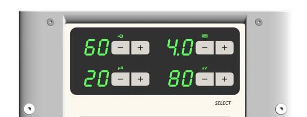
V 09/13

General safety regulations

                                This chapter sets out the fundamental safety regulations that must be fol-
                                lowed by the user and third parties using the OptiStar CG06 Automatic
                                gun control unit.
                                These safety regulations must be read and understood before the Op-
                                tiStar CG06 Automatic gun control unit is used.

Safety symbols (pictograms)
                                The following warnings with their meanings can be found in the Gema
                                operating instructions. The general safety precautions must also be fol-
                                lowed as well as the regulations in the operating instructions.

                                DANGER!
                                Danger due to live electricity or moving parts. Possible consequences:
                                Death or serious injury

                                ATTENTION!
                                Improper use of the equipment could damage the machine or cause it to
                                malfunction. Possible consequences: minor injuries or damage to equip-
                                ment

                                NOTE!
                                Useful tips and other information

Conformity of use
                                    1. The OptiStar CG06 Automatic gun control unit is built to the lat-
                                       est specification and conforms to the recognized technical safety
                                       regulations. It is designed for the normal application of powder
                                       coating.
                                    2. Any other use is considered as non-conform. The manufacturer
                                       is not responsible for damage resulting from improper use of this
                                       equipment; the end-user alone is responsible. If the OptiStar
                                       CG06 Automatic gun control unit is to be used for other purposes
                                       or other substances outside of our guidelines then Gema Swit-
                                       zerland GmbH should be consulted.
                                    3. Observance of the operating, service and maintenance instruc-
                                       tions specified by the manufacturer is also part of conformity of

OptiStar CG06 Automatic gun control unit                                    General safety regulations • 5
V 09/13
use. The OptiStar CG06 Automatic gun control unit should only
be used, maintained and started up by trained personnel, who
are informed about and are familiar with the possible hazards in-
volved.
4. Start-up (i.e. the execution of a particular operation) is forbidden
until it has been established that the OptiStar CG06 Automatic
gun control unit has been set up and wired according to the
guidelines for machinery (2006/42 EG). EN 60204-1 (machine
safety) must also be observed.
5. Unauthorized modifications to OptiStar CG06 Automatic gun con-
trol unit exempt the manufacturer from any liability from resulting
damage.
6. The relevant accident prevention regulations, as well as other
generally recognized safety regulations, occupational health and
structural regulations are to be observed.
7. Furthermore the country-specific safety regulations must be ob-
served.
Explosion protection Protection type Temperature class
T6 (zone 21)
IP54
II (2) 3 D T4 (zone 22)
Technical safety regulations for stationary electrostat-
ic powder spraying equipment
General information
The powder spraying equipment from Gema is designed with safety in
mind and is built according to the latest technological specifications. This
equipment can be dangerous if it is not used for its specified purpose.
Consequently it should be noted that there exists a danger to life and
limb of the user or third party, a danger of damage to the equipment and
other machinery belonging to the user and a hazard to the efficient op-
eration of the equipment.
1. The powder spraying equipment should only be started up and
used once the operating instructions have been carefully studied.
Improper use of the controlling device can lead to accidents, mal-
function or damage to the control itself.
2. Before every start-up check the equipment for operational safety
(regular servicing is essential)!
3. Safety regulations BGI 764 and VDE regulations DIN VDE 0147,
Part 1, must be observed for safe operation.
4. Safety precautions specified by local legislation must be ob-
served.
5. The plug must be disconnected before the machine is opened for
repair.
6. The plug and socket connection between the powder spraying
equipment and the mains network should only be taken out when
the power is switched off.
6 • General safety regulations OptiStar CG06 Automatic gun control unitV 09/13
7. The connecting cable between the controlling device and the
spray gun must be set up so that it cannot be damaged during
operation. Safety precautions specified by local legislation must
be observed!
8. Only original Gema spare parts should be used, because the ex-
plosion protection will also be preserved that way. Damage
caused by other parts is not covered by guarantee.
9. If Gema powder spraying equipment is used in conjunction with
machinery from other manufacturers then their safety regulations
must also be taken into account.
10. Before starting work familiarize yourself with all installations and
operating elements, as well as with their functions! Familiariza-
tion during operation is too late!
11. Caution must be exercised when working with a powder/air mix-
ture! A powder/air mixture in the right concentration is flammable!
Smoking is forbidden in the entire plant area!
12. As a general rule for all powder spraying installations, persons
with pacemakers should never enter high voltage areas or areas
with electromagnetic fields. Persons with pacemakers should not
enter areas with powder spraying installations!
ATTENTION!
We emphasize that the customer himself is responsible for the safe
operation of equipment. Gema is in no way responsible for any re-
sulting damages!
Safety conscious working
Each person responsible for the assembly, start-up, operation, service
and repair of powder spraying equipment must have read and under-
stood the operating instructions and the "Safety regulations"-chapter. The
operator must ensure that the user has had the appropriate training for
powder spraying equipment and is aware of the possible sources of dan-
ger.
The control units for the spray guns must only be set up and used in zone
22. The spray guns are permitted in the zone 21 created by them.
The powder spraying equipment should only be used by trained and au-
thorized personnel. This applies to modifications to the electrical equip-
ment, which should only be carried out by a specialist.
The operating instructions and the necessary closing down procedures
must be followed before any work is carried out concerning the set-up,
start-up, operation, modification, operating conditions, mode of operation,
servicing, inspection or repairs.
The powder spray equipment can be turned off by using the main switch
or failing that, the emergency shut-down. Individual components can be
turned off during operation by using the appropriate switches.
Individual safety regulations for the operating
firm and/or operating personnel
1. Any operating method which will negatively influence the tech-
nical safety of the powder spraying equipment is to be avoided.
OptiStar CG06 Automatic gun control unit General safety regulations • 7V 09/13
2. The operator should care about no non-authorized personnel
works on the powder spraying equipment (e.g. this also includes
using the equipment for non-conform work).
3. For dangerous materials, the employer has to provide an operat-
ing instructions manual for specifying the dangers arising for hu-
mans and environment by handling dangerous materials, as well
as the necessary preventive measures and behavior rules. The
operating instructions manual has to be written in an under-
standable form and in the language of the persons employed,
and has to be announced in a suitable place in the working area.
4. The operator is under obligation to check the powder spraying
equipment at least once every shift for signs of external damage,
defects or changes (including the operating characteristics)
which could influence safety and to report them immediately.
5. The operator is obliged to check that the powder spraying
equipment is only operated when in satisfactory condition.
6. As far as it is necessary, the operating firm must ensure that the
operating personnel wear protective clothing (e.g. facemasks).
7. The operating firm must guarantee cleanliness and an overview
of the workplace with suitable instructions and checks in and
around the powder spraying equipment.
8. No safety devices should be dismantled or put out of operation. If
the dismantling of a safety device for set-up, repair or servicing is
necessary, reassembly of the safety devices must take place
immediately after the maintenance or repair work is finished. The
powder spraying device must be turned off while servicing is car-
ried out. The operator must train and commit the responsible
personnel to this.
9. Activities such as checking powder fluidization or checking the
high voltage spray gun etc. must be carried out with the powder
spraying equipment switched on.
Notes on special types of hazard
Power
It is necessary to refer once more to the danger of life from high voltage
current if the shut-down procedures are not observed. High voltage
equipment must not be opened - the plug must first be taken out - other-
wise there is danger of electric shock.
Powder
Powder/air mixtures can be ignited by sparks. There must be sufficient
ventilation in the powder coating booth. Powder lying on the floor around
the powder spraying device is a potentially dangerous source of slipping.
Static charges
Static charges can have the following consequences: Charges to people,
electric shocks, sparking. Charging of objects must be avoided - see
"Earthing".
Grounding/Earthing
All electricity conducting parts and machinery found in the workplace (ac-
cording to DIN VDE 0745, part 102) must be earthed 1.5 meters either
8 • General safety regulations OptiStar CG06 Automatic gun control unitV 09/13
side and 2.5 meters around each booth opening. The earthing resistance
must amount to maximally 1 MOhm. The resistance must be tested on a
regular basis. The condition of the machinery surroundings as well as the
suspension gear must ensure that the machinery remains earthed. If the
earthing of the machinery includes the suspension arrangements, then
these must constantly be kept clean in order to guarantee the necessary
conductivity. The appropriate measuring devices must be kept ready in
the workplace in order to check the earthing.
Compressed air
When there are longer pauses or stand-still times between working, the
powder spraying equipment should be drained of compressed air. There
is a danger of injury when pneumatic hoses are damaged and from the
uncontrolled release and improper use of compressed air.
Crushing and cutting
During operation, moving parts may automatically start to move in the
operating area. It must be ensured that only instructed and trained per-
sonnel go near these parts. The operator should ensure that barriers
comply with the local security regulations.
Access under exceptional circumstances
The operating firm must ensure that local conditions are met when re-
pairs are made to the electronic parts or when the equipment is restarted
so that there are additional measures such as barriers to prevent unau-
thorized access.
Prohibition of unauthorized conversions and modifica-
tions to machines
All unauthorized conversions and modifications to electrostatic spraying
equipment are forbidden for safety reasons.
The powder spraying equipment should not be used if damaged, the
faulty part must be immediately replaced or repaired. Only original Gema
replacement parts should be used. Damage caused by other parts is not
covered by guarantee.
Repairs must only be carried out by specialists or in Gema workshops.
Unauthorized conversions and modifications may lead to injury or dam-
age to machinery. The Gema Switzerland GmbH guarantee would no
longer be valid.
Safety requirements for electrostatic powder
coating
1. This equipment is dangerous if the instructions in this operating
manual are not followed.
2. All electrostatic conductive parts, in particular the machinery
within 5 meters of the coating equipment, must be earthed.
3. The floor of the coating area must conduct electricity (normal
concrete is generally conductive).
4. The operating personnel must wear electricity conducting foot-
wear (e.g. leather soles).
5. The operating personnel should hold the gun with bare hands. If
gloves are worn, these must also conduct electricity.
OptiStar CG06 Automatic gun control unit General safety regulations • 9V 09/13
6. The supplied earthing cable (green/yellow) must be connected to
the earthing screw of the electrostatic powder spraying hand ap-
pliance. The earthing cable must have a good metallic connec-
tion with the coating booth, the recovery unit and the conveyor
chain and with the suspension arrangement of the objects.
7. The electricity and powder supply to the hand guns must be set
up so that they are fully protected against heat and chemical
damage.
8. The powder coating device may only be switched on once the
booth has been started up. If the booth cuts out then the powder
coating device must be switched off.
9. The earthing of all electricity conducting devices (e.g. hooks,
conveyor chains) must be checked on a weekly basis. The earth-
ing resistance must amount to maximally 1 MOhm.
10. The control device must be switched off if the hand gun is
cleaned or the nozzle is changed.
11. When working with cleaning agents there may be a risk of haz-
ardous fumes. The manufacturer's instructions must be observed
when using such cleaning agents.
12. The manufacturer's instructions and the applicable environmental
requirements must be observed when disposing of powder lac-
quer and cleaning agents.
13. If any part of the spray gun is damaged (broken parts, tears) or
missing then it should not be used.
14. For your own safety, only use accessories and attachments listed
in the operating instructions. The use of other parts can lead to
risk of injury. Only original Gema replacement parts should be
used.
15. Repairs must only be carried out by specialists and under no cir-
cumstances should they be carried out in the operating area. The
former protection must not be reduced.
16. Conditions leading to dangerous levels of dust concentration in
the powder spraying booths or in the powder spraying areas
must be avoided. There must be sufficient technical ventilation
available, to prevent a dust concentration of more than 50% of
the lower explosion limit (UEG) (UEG = max. permissible pow-
der/air concentration). If the UEG is not known then a value of 10
g/m³ should be used.
A summary of the rules and regulations
The following is a list of relevant rules and regulations which are to be
observed:
Guidelines and regulations, German professional asso-
ciation
BGV A1 Prevention principles
BGV A3 Electrical equipment and material
BGI 764 Electrostatic coating
BGR 132 Guidelines for the avoidance of the dangers of ignition
due to electrostatic charging (guideline "Static Electrici-
ty")
10 • General safety regulations OptiStar CG06 Automatic gun control unitV 09/13
VDMA 24371 Guidelines for electrostatic coating with synthetic pow-
der1)
- Part 1 General requirements
- Part 2 Examples of use
EN European standards
RL94/9/EC The approximation of the laws of the Member States
relating to apparatus and safety systems for their in-
tended use in potentially explosive atmospheres
EN 12100-1 Machine safety 2)
EN 12100-2
EN IEC 60079-0 Electrical equipment for locations where there is danger
of explosion 3)
EN 50 050 Electrical apparatus for potentially explosive atmos-
pheres - electrostatic hand-held spraying equipment 2)
EN 50 053, part 2 Requirements for the selection, installation and use of
electrostatic spraying equipment for flammable materi-
als - hand-held electrostatic powder spray guns 2)
EN 50 177 Stationary electrostatic spraying equipment for flamma-
ble coating powder 2)
EN 12981 Coating plants - spray booths for application of organic
powder coating material - safety requirements
EN 60 529, identi- IP-Type protection: contact, foreign bodies and water
2)
cal: DIN 40050 protection for electrical equipment
EN 60 204 identi- VDE regulations for the setting up of high voltage elec-
cal: DIN VDE 0113 trical machine tools and processing machines with
mains voltages up to 1000 V 3)
VDE (Association of German Engineers) Regulations
DIN VDE 0100 Regulations for setting-up high voltage equipment with
mains voltages up to 1000 V 4)
DIN VDE 0105 VDE regulations for the operation of high voltage
4)
equipment
part 1 General regulations
part 4 Supplementary definitions for stationary electrical spray-
ing equipment
DIN VDE 0147 Setting up stationary electrostatic spraying equipment 4)
part 1
DIN VDE 0165 Setting up electrical equipment in locations in areas with
danger of explosion 4)
*Sources:
1)
Carl Heymanns Verlag KG, Luxemburger Strasse 449, 5000 Köln 41,
or from the appropriate employers association
2)
Beuth Verlag GmbH, Burgrafenstrasse 4, 1000 Berlin 30
3)
General secretariat, Rue Bréderode 2, B-1000 Bruxelles, or the appro-
priate national committee
4)
VDE Verlag GmbH, Bismarckstrasse 33, 1000 Berlin 12
OptiStar CG06 Automatic gun control unit General safety regulations • 11V 09/13
Product specific security measures
- The installation work, to be done by the customer, must be
carried out according to local regulations
- Before starting up the plant a check must be made that no
foreign objects are in the booth or in the ducting (input and
exhaust air)
- It must be observed, that all components are grounded ac-
cording to the local regulations, before start-up
12 • General safety regulations OptiStar CG06 Automatic gun control unitV 09/13
About this manual
General information
This operating manual contains all the important information which you re-
quire for the working with the OptiStar CG06 Automatic gun control unit. It
will safely guide you through the start-up process and give you references
and tips for the optimal use of your new powder coating system.
Information about the function mode of the individual system components
- reciprocators, booths, powder gun controls, powder guns etc. - should
be referenced to their corresponding documents.
Software version
This document describes the operation of the OptiStar CG06 Gun control
unit, with software version starting from 1.05!
OptiStar CG06 Automatic gun control unit About this manual • 13V 09/13
Function description
Field of application
The OptiStar CG06 Automatic gun control unit is designed exclusively for
controlling the Gema powder coating guns (see also in chapter "Tech-
nical Data").
Any other use, beyond the above mentioned is considered non-
conforming. The manufacturer is not responsible for any damage result-
ing from this, the risk for this is assumed by the user alone!
For a better understanding of the relationships in powder coating, it is
recommended to read the operating instructions of other components,
thoroughly, so as to be familiar with their functions also.
OptiStar CG06 Automatic gun control unit
Typical characteristics
- The OptiStar CG06 Automatic gun control unit is used for au-
tomatic electrostatic powder coating equipment.
- The OptiStar CG06 Automatic gun control unit allows the
configuration of process parameters (air settings, high volt-
age settings), system parameters, process data, status in-
formation and the powder hose correction values. All air vol-
umes can be controlled centrally by the unit.
- The handling is simple and self-explanatory. The coating
personnel can save individual settings, based off personnel
experience, in 250 different programs.
- All settings for efficient powder coating are simple to operate
and repeatable. The control unit electronics permit the exact
amount of powder delivery and the adjusted values can be
read on the digital displays.
- Optional bus connections by CAN bus and DigitalBus allow a
simple, superordinated control.
- A shaping air option is available, in combination with a flow
control for all four air types.
- The OptiStar CG06 unit can be connected to all mains volt-
ages between 100-240VAC, 50-60 Hz, single phase.
OptiStar CG06 Automatic gun control unit Function description • 15V 09/13
Basic functions
- Intuitive operation
- Setting and display of the values on two levels
- Saving/recalling of process parameters in the form of pro-
grams
- Remote control option on the manual powder gun (OptiSelect
GM02 only)
Additional functions
- Spray current regulation with high voltage limitation
- Control of the air volumes
- Status indications and error diagnosis
- Several input air pressures are definable with parameteriza-
tion
- Flow control for total air (conveying air plus supplementary
air), electrode rinsing air and shaping air (optional)
- Bus connections by CAN bus or DigitalBus (optional)
OptiStar CG06 functions - overview
Setting possibilities
- Setting possibilities for powder rate, total air, spray current,
high voltage, electrode rinsing air and shaping air (option)
Correction values
- Correction values for powder offset, powder hose correction
value and daily correction value
Request values
- Request values for software version and trigger hours coun-
ter
Features
- Keyboard lock, Preset mode, 250 programs, error display
and remote control on manual gun (OptiSelect GM02)
Options
- Flow control and shaping air, CAN bus and DigitalBus
16 • Function description OptiStar CG06 Automatic gun control unitV 09/13
Operating modes
The OptiStar CG06 Automatic gun control unit can be operated with two
operating modes. According to the selected application mode, spray volt-
age and spray current are automatically adjusted and limited.
Predefined operating mode (Preset mode)
The OptiStar CG06 Automatic gun control unit provides three predefined
application modes (flat parts, complicated parts and recoat parts already
painted one time).
In this operating mode, current (µA) and high voltage (kV) are preset,
powder and air volume can be adjusted and saved.
The remaining preset values are not changed by transition to the prede-
fined operating mode, they can be configured furthermore and will be
saved in memory.
User-defined operating mode (Program mode)
In this operating mode, 250 individually definable programs (P001-P250)
are available. These programs are automatically saved and can be re-
called again as the application requires.
The values for current, high voltage, powder output, total air, electrode
rinsing air and fluidizing air (if available) can be set as needed for a given
application.
NOTE:
The specified settings in the 250 programs and 3 application modes
are saved automatically, without confirmation, after a two second
delay and the display changes from preset values to actual values!
OptiStar CG06 Automatic gun control unit Function description • 17V 09/13
Technical Data
OptiStar CG06 Gun control unit
OptiStar CG06 - versions
Shaping
OptiStar CAN bus DigitalBus FlowControl
air
CG06
CG06-C yes
CG06-CF yes yes yes
CG06-D yes
CG06-DF yes yes yes
The equipment designation is indicated on the rear side of the equip-
ment.
Connectable guns
OptiStar CG06 Gun control unit connectable
OptiSelect GM02 yes
OptiGun GA02 yes
yes (no remote control on
PG1 / PG2-A / PG2-AX
gun)
PG3-E** yes
TriboJet* (adapter required) yes
EasySelect GM01 no
* The gun type must be adjusted (reference chapter "Additional func-
tions")! The Tribo gun is not type approved (ATEX).
** Only for enamel powder, the gun is not type approved (ATEX).
ATTENTION:
The OptiStar CG06 Automatic gun control unit can only be used
with the specified gun types!
OptiStar CG06 Automatic gun control unit Technical Data • 19V 09/13
Electrical data
OptiStar CG06 Gun control unit
Mains input voltage 100-240 VAC
Operating frequency 50-60 Hz
Input power 40 VA
Nominal output voltage (to the gun) max. 12 V
Nominal output current (to the gun) max. 1 A
Protection type IP54
0 °C - +40 °C
Ambient temperature range
(+32 °F - +104 °F)
Max. operating temperature 85 °C (+185 °F)
Approvals II (2) 3 D
PTB05 ATEX 5009
FM approvals (pending)
Pneumatical data
OptiStar CG06 Gun control unit
Compressed air connection 1/4" male quick release
5.5 bar
Input pressures (must be set in the software) 6.0 bar
6.5 bar
Max. input pressure 10 bar / 145 psi
Min. input pressure (while unit in operation) 6 bar / 87 psi
Max. water vapor content of the compressed air 1.3 g/m³
Max. oil vapor content of the compressed air 0.1 mg/m³
Dimensions
OptiStar CG06 Gun control unit
Width 248 mm
Depth 250 mm
Height 174 mm
Weight approx. 5.2 kg
20 • Technical Data OptiStar CG06 Automatic gun control unitV 09/13
Air flow rates
The total air consists of conveying air and supplementary air, in relation
to the selected powder quantity (in %). Hereby, the total air volume is
maintained constant. For explanation, see the following examples with
correction factor C0=1.8 and conveying air nozzle=1.4 mm.
This table refers to an input pressure of 5.5 bar (system parameter
P2=0).
OptiStar CG06 Gun control unit
Powder Supplementary
Total air Conveying air
quantity air
81 % 5.4 Nm³/h 1.1 Nm³/h
6.5 Nm³/h 40 % 3.7 Nm³/h 2.8 Nm³/h
0% 1.8 Nm³/h 4.7 Nm³/h
100 % 5.5 Nm³/h 0 Nm³/h
5.5 Nm³/h 50 % 3.6 Nm³/h 1.9 Nm³/h
0% 1.8 Nm³/h 3.7 Nm³/h
100 % 4.0 Nm³/h 0 Nm³/h
4.0 Nm³/h 50 % 2.8 Nm³/h 1.2 Nm³/h
0% 1.8 Nm³/h 2.2 Nm³/h
OptiStar CG06 Gun control unit
Fluidizing air flow rate 0-5.0 Nm³/h
Electrode rinsing air flow rate 0-3.0 Nm³/h
Conveying air flow rate 0-5.4 Nm³/h
Supplementary air flow rate 0-4.5 Nm³/h
NOTE:
The total air consumption without FlowControl and shaping air
amounts to max. 10.5 Nm³/h (with a parameterized input pressure of
6.5 bar)!
The total air consumption with FlowControl and shaping air
amounts to max. 15.5 Nm³/h (with a parameterized input pressure of
6.5 bar)!
OptiStar CG06 Automatic gun control unit Technical Data • 21V 09/13
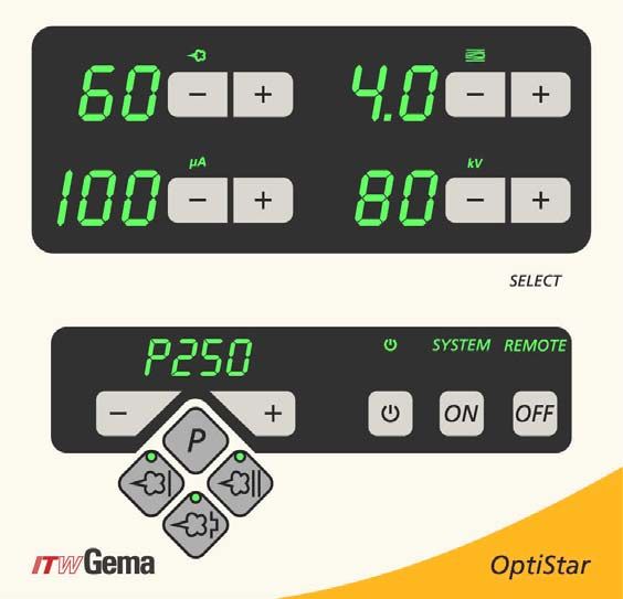
Operating and display elements
Display and LEDs
L1 L2
A1 A2
L3 L4 L5 L6
A3 A4
L7 L8 L9
A5
L13 L15
L14
OptiStar CG06 Automatic gun control unit - display and LEDs
Designation Function
Display of actual values, preset values and system param-
A1-A4
eters
Display of program numbers, error diagnosis codes and
A5
status information
L1 Powder output (display in %)
L2 Total air volume (display in Nm³/h)
L3 Spraying current (display in µA)
L4 Shaping air (display in Nm³/h, if available)
L5 High voltage (display in kV)
L6 Electrode rinsing air (display in Nm³/h)
L7 Gun enable display
L8 External release signal (from superordinated control unit)
OptiStar CG06 Automatic gun control unit Operating and display elements • 23V 09/13
Designation Function
L9 Remote PLC control
L13 Application mode for flat parts is activated
L14 Application mode for complicated parts is activated
Application mode for recoating parts already coated is ac-
L15
tivated
Input keys and switches
T1 T2 T3 T4
T5 T6 T7 T8
T9
T16 S1 S2
T10 T12 T11
T13 T15
T14
OptiStar CG06 Automatic gun control unit - input keys and switches
Designation Function
T1-T8 Input keys for preset values and system parameters
T9 (Select) Switch between display levels
T10-T11 Program change
T12 (P) Program selection for user-defined programs (max. 250)
T13 Application mode for flat parts (fixed values)
Application mode for complicated parts with depressions
T14
(fixed values)
Application mode for overcoating parts already coated
T15
(fixed values)
Switching the gun on and off (system input must be active)
T16 Switch to system parameter mode (press for at least 5 se-
conds)
S1/S2 Power switch On/Off
24 • Operating and display elements OptiStar CG06 Automatic gun control unitV 09/13
General information
Displaying the programs
The number of the adjusted program is shown on display A5. A
P=Program is placed in front of the three digit program number as a ref-
erence.
Displaying the values
Displaying the actual values
The actual values are shown on the displays A1-A4. By operating the
keys T1-T8 and T12-T15, preset values display will be switched over.
Display of the preset values/setting values
The preset values are shown on the displays A1-A4. If no operation
takes place during 3 seconds, the actual values displayed will be
switched over.
Edit and save the preset values
The preset values can be adjusted in steps by ± 1 with the keys T1-T8.
Modified preset values are saved automatically, after 2 seconds, in the
current program.
Change between program and application mode
Pressing the keys T10 and T11 in one of the three predefined application
modes (Preset mode), causes the unit to change to user-defined pro-
grams. These keys also allow the change of programs in the program
mode.
The simultaneous operation of the + and - key on the back of the powder
gun (OptiSelect gun) causes the control unit to rotate between the Preset
mode and the Program mode.
Viewing of preset values
To change from the actual value to the preset value display without
changing a preset value at the same time, the corresponding keys must
be lightly touched.
Example:
Lightly touching key T1 indicates the preset values, pushing harder on
this key, reduces the powder output. This behavior does not apply to the
program select keys, where the program number is directly changed.
OptiStar CG06 Automatic gun control unit Operating and display elements • 25V 09/13
Start-up and operation
OptiStar CG06 connections
OptiStar CG06 Automatic gun control unit - connections on the rear wall
Connection Description
1.1 Air Supply IN Compressed air connection (6-10 bar / 87-145 PSI)
2.1 Power IN Mains cable connection (100-240 VAC)
2.2 Gun Gun cable connection
2.3 Aux CAN bus connection (OUT)
2.4 Aux CAN bus connection (IN)
2.4 Aux DigitalBus connection (option)
1.5 Shaping air connection (option)
1.4 Electrode rinsing air connection
1.3 Supplementary air connection
1.2 Conveying air connection
Grounding connection
OptiStar CG06 Automatic gun control unit Start-up and operation • 27V 09/13
2.3 and 2.4 Aux connections
Equipment Allocation 2.3 Allocation 2.4
CG06 closed closed
CG06-C(F) CAN bus (OUT) CAN bus (IN)
CG06-D(F) closed DigitalBus
Connection guide
1. Connect the compressed air supply from the compressed air
circuit to the 1.1 Air supply IN (1/4" male quick release)
connection on the control unit
NOTE:
The compressed air must be free from oil and water!
2. Connect the grounding cable to the control unit with the
grounding screw, and the 5 m long grounding cable with the
clamping clip to the booth or the conveyor. Check ground
connections with Ohm meter and ensure 1 MOhm or less
3. Connect the gun cable plug to the socket 2.2 on the rear side
of the control unit
4. Connect the rinsing air hose to the electrode rinsing air out-
put 1.4 and to the powder gun
5. Insert the injector, connect the powder hose to the injector
and to the powder gun
6. Connect the red hose for the conveying air to the correspond-
ing output 1.2 on the rear of the control unit and to the injector
7. Connect the black hose for supplementary air to the corre-
sponding output 1.3 on the rear side of the control unit and to
the injector (this hose is electrically conductive)
8. Connect the hose for shaping air (optional) to the corre-
sponding output 1.5 on the rear side of the control unit
9. Connect the mains cable to the 2.1 Power IN plug and screw it on
Pressure regulator Powder gun
after filter
(5.5/6.0/6.5 bar)
Shaping air (optional)
Injector
Connecting guide - overview
28 • Start-up and operation OptiStar CG06 Automatic gun control unitV 09/13
CG06 pin assignment
Power IN connection
2 1 Neutral conductor (power supply)
PE 3 2 Phase conductor (100-240 VAC)
1
3 Input System ON/OFF (90-240 VAC)
PE Ground PE
Gun connection
1 Ground
2 Remote control 1 (GM02)
3
4 2 3 Ground
PE 1 4 Trigger
5
6 5 Remote control 2 (GM02)
6 Oscillator
7 Ground PE
CG06-C(F) pin assignment
2 3
CAN IN socket with 4 pins (2.4 Aux)
1 Ground
1 4
2 24 VDC
3 CAN high
4 CAN low
Enclosure - shield
CAN OUT plug with 4 pins (2.3 Aux)
1 Ground
3 2 2 24 VDC
3 CAN high
4 1 4 CAN low
Enclosure - shield
CG06-D(F) pin assignment
DigitalBus plug with 19 pins (2.4 Aux)
Pin Bit Function (binary value)
A 1 IN-D0 Preset values, program number binary value 20 (=1)
B 2 IN-D1 Preset values, program number binary value 21 (=2)
C 3 IN-D2 Preset values, program number binary value 22 (=4)
D 4 IN-D3 Preset values, program number binary value 23 (=8)
E 5 IN-D4 Preset values, program number binary value 24 (=16)
F 6 IN-D5 Preset values, program number binary value 25 (=32)
G 7 IN-D6 Preset values, program number binary value 26 (=64)
H 8 IN-D7 Preset values, program number binary value 27 (=128)
J 9 IN-A0 Identification number binary value 20 (=1)
K 10 IN-A1 Identification number binary value 21 (=2)
OptiStar CG06 Automatic gun control unit Start-up and operation • 29V 09/13
Pin Bit Function (binary value)
L 11 IN-A2 Identification number binary value 22 (=4)
M 12 IN System ON/OFF (gun release)
N 13 IN Strobe (data transfer from data Bus)
O 14 IN Remote/manual
P 15 IN Preset values program no. binary value 2^8 (=256) reserve
R 16 IN GND external
S 1 OUT Composite error message (signal: Error)
T 2 OUT System activated
U 24 VDC external
Enclosure Shield
Initial start-up
Setting the device type
Adjust the corresponding device type (manual device types or automatic
device) with the system parameter P0 (see therefore in chapter "System
parameters").
NOTE:
If the control unit is supplied as a component of an OptiFlex auto-
matic unit, then the corresponding system parameter is set correct-
ly by the factory!
System parameter P0=3
Preparing the powder hopper/container
Prepare the powder hopper or powder box (reference the corresponding
operating manual).
Switch on the booth
Switch on the powder coating booth according to its operating manual.
Daily start up
The daily start-up of the OptiStar CG06 Automatic gun control unit takes
place by the following steps:
Select the operating mode
Select the application mode with three predefined modes (Preset mode)
or the user-defined program mode with 250 adjustable programs (Pro-
gram mode).
1. Turn on the gun control unit with the ON key
2. Select the corresponding application mode with key T12 (for
Program mode) or keys T13/T14/T15 (for Preset mode)
30 • Start-up and operation OptiStar CG06 Automatic gun control unitV 09/13
The predefined mode automatically set values for high voltage and spray-
ing current:
Presetting Desired µA Desired kV
Flat parts 100 100
Complicated parts 22 100
Overcoating 10 100
Starting the predefined operating mode (Preset mode)
Select the preset mode with the application keys T13/T14/T15. The LED
of the corresponding application key illuminates. No program number will
be shown on the display A5. The values for powder output and total air
volume, indicated before the changeover, are maintained.
Application mode for flat parts
This application mode is suitable for the coating of simple, flat workpieces
without larger cavities.
Application mode for complicated parts
This application mode is suitable for the coating of three-dimensional
workpieces with complicated shapes (e.g. profiles).
Application mode for recoating parts already coated
This application mode is suitable for the over-coating of workpieces
which are already coated.
Exiting the Preset mode
Exit the Preset mode with the keys T10, T11 or T12. The preset values of
the Program mode used before the Preset mode are displayed by the
control unit memory.
Starting the user-defined operating mode (Program
mode)
Select this application mode with the program key T12. Here, 250 indi-
vidually adjustable programs can be defined and saved. The programs 1-
250 were loaded with presets by factory. Factory preset values are 60%
powder output at 4.0Nm³/h total air and 20µA spray current at 80kV high
voltage.
Setting powder output and powder cloud
The powder output is dependent on the selected powder output (in %)
and the selected total air volume.
Setting the total air volume
1. Adjust the total air volume with the keys T3/T4 (see also the
injector operating manual)
- Adjust the total air volume according to the correspond-
ing coating requests
OptiStar CG06 Automatic gun control unit Start-up and operation • 31V 09/13
Setting the powder output
2. Adjust the powder output volume (e.g. according to the de-
sired coating thickness)
- The selection takes place with the keys T1/T2 on the
control unit or with the +/- keys on the rear side of the
powder gun (OptiSelect gun type). Factory default setting
of 60% is recommended for initial spraying. The total air
volume is maintained constant automatically
3. Release the OptiStar CG06 control unit by superordinated
control unit (external release signal)
4. Activate the gun with the key T16, the LED L7 illuminates
5. If a manual gun is connected, point it into the booth and
press the gun trigger
NOTE:
As a factory default value, a powder rate of 60% and a total air vol-
ume of 4 Nm³/h are recommended.
By inserting values, which the equipment cannot convert, the opera-
tor is made aware by flashing of the appropriate display and a tem-
porary out of range message!
OptiStar CG06 gun release
In order that the gun can spray powder, no error may be present, which
causes the control unit to deactivate the gun. Furthermore, depending on
the device, the following conditions must be complied:
OptiStar CG06 with DigitalBus:
- SYSTEM activated, DigitalBus or SYSTEM (Power In)
- Gun release activated
- Trigger pressed (manual gun only)
OptiStar CG06 with CAN bus:
- SYSTEM (Power In)
- Gun release by CAN bus
- Trigger pressed (manual gun only)
OptiStar CG06 without bus connection:
- SYSTEM (Power In)
- Gun release
- Trigger pressed (manual gun only)
32 • Start-up and operation OptiStar CG06 Automatic gun control unitV 09/13
Trigger (gun)
Sys (mains input)
SYS (DigitalBus)
System release
Gun key System release logic
Release by CAN
Error Lock
System Lock
Internal signals are derived from input signals, which are logically linked
together:
Ext. release
Gun release
System release
Trigger
Error Lock
System Lock
System release
Setting the electrode rinsing air
1. Adjust the correct electrode rinsing air according to the ap-
plied nozzles (deflector plate, flat jet nozzle)
- Press key T9 (SELECT)
The second display level is switched over
- Press keys T7/T8
Here, the corresponding air volume value is entered
- If this display level is not operated for 3 seconds, the first
display level is switched over independently
NOTE:
By using flat jet nozzles, the factory default value is approx. 0.2
Nm³/h, by using round jet nozzles with air-rinsed deflector plates,
the factory default value is approx. 0.5 Nm³/h!
Setting the shaping air (optional)
Procedure:
1. Press key T9 (SELECT)
The second display level is switched over
2. Adjust the shaping air with the keys T5/T6
- If this display level is not operated for 3 seconds, the first
display level is switched over independently
OptiStar CG06 Automatic gun control unit Start-up and operation • 33V 09/13
Powder coating
ATTENTION:
Make sure first, that all electrically conductive parts within 5 m of
the coating booth are grounded!
1. Point the gun into the coating booth, but do not yet direct it to
the object to be coated
2. Select the operating mode:
Select the operating mode with program key T12 or applica-
tion keys T13/T14/T15. The LED of the corresponding appli-
cation key illuminates
3. Coat the objects
Remote control by OptiSelect GM02 manual gun
Various functions can be remotely controlled with the + and - keys on the
rear side of the powder gun (OptiSelect gun type):
- Modify the powder output (press the + or - key on the gun).
The powder output will be increased or decreased according-
ly
- Change application modes (Preset mode/Program mode) by
pressing the + and - keys on the gun at the same time. The
change takes place counterclockwise. Check by observing
the key LEDs on the control unit
NOTE:
By pressing one of the keys, the preset values will be displayed
versus the actual values!
Shut-down
The shut-down of the OptiStar CG06 Automatic gun control unit takes
place in following steps:
1. Switch off externally by superordinated control unit, or on the
control unit with key T16 (local operation)
2. In the case of PLC controlled systems, shut-down can take
place directly with the key S2
NOTE:
The adjustments for high voltage, powder output, electrode rinsing
air and fluidizing remain stored!
Saving programs
NOTE:
The values in programs 1-250 and the 3 preset application modes
are saved automatically, without confirmation!
34 • Start-up and operation OptiStar CG06 Automatic gun control unitV 09/13
Technical explanations concerning high voltage and
spray current
Characteristic curves of Preset mode
The preset values for high voltage and spray current in the predefined
operation mode (Preset mode) are to be taken as reference points. The
modification of these values has effects on the characteristic curve of the
gun (see diagram). The operator can optimize the application within the
possible 3 ranges.
Characteristic curves of Preset mode
Preset values:
Flat parts: 100kV/100uA
Complicated parts: 100kV/22uA
Overcoating: 100kV/10uA
High voltage (kV)
Spray Current (µA)
Characteristic curve of Program mode
In the user-defined operating mode (Program mode), the values for high
voltage and spray current are adjustable. The operator can optimize the
values for his application by utilizing the ranges below (see diagram).
Characteristic curve of Program mode
High voltage (kV)
Spray current (µA)
OptiStar CG06 Automatic gun control unit Start-up and operation • 35You can also read