IPL Pro Series User Guide - IP Link Pro Products - Extron
←
→
Page content transcription
If your browser does not render page correctly, please read the page content below
User Guide
                                 IP Link Pro® Products

IPL Pro Series
IP Link Pro Control Processors

                                                 68-2437-01 Rev. H
                                                             01 21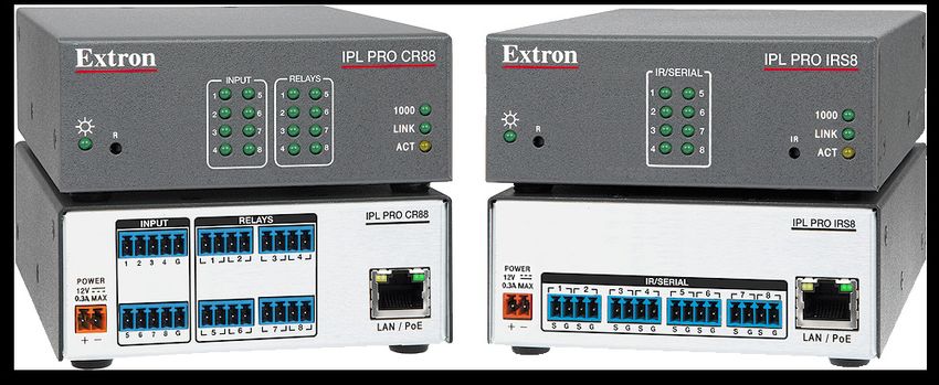
Safety Instructions
Copyright
© 2014-2021 Extron. All rights reserved. www.extron.com

Trademarks
All trademarks mentioned in this guide are the properties of their respective owners.
The following registered trademarks (®), registered service marks (SM), and trademarks (™) are the property of RGB Systems, Inc. or Extron (see the current list
of trademarks on the Terms of Use page at www.extron.com):

                                                                 Registered Trademarks (®)
 Extron, Cable Cubby, ControlScript, CrossPoint, DTP, eBUS, EDID Manager, EDID Minder, eLink, Flat Field, FlexOS, Glitch Free, Global Configurator,
 Global Scripter, GlobalViewer, Hideaway, HyperLane, IP Intercom, IP Link, Key Minder, LinkLicense, LockIt, MediaLink, MediaPort, NAV,
 NetPA, PlenumVault, PoleVault, PowerCage, PURE3, Quantum, ShareLink, Show Me, SoundField, SpeedMount, SpeedSwitch, StudioStation,
 System Integrator, TeamWork, TouchLink, V‑Lock, VideoLounge, VN‑Matrix, VoiceLift, WallVault, WindoWall, XPA, XTP, XTP Systems, and ZipClip
 Registered Service Mark(SM) : S3 Service Support Solutions
                                                                       Trademarks (™)
 AAP, AFL (Accu‑RATE Frame Lock), ADSP (Advanced Digital Sync Processing), AVEdge, CableCover, CDRS (Class D Ripple Suppression), Codec
 Connect, DDSP (Digital Display Sync Processing), DMI (Dynamic Motion Interpolation), Driver Configurator, DSP Configurator, DSVP (Digital Sync
 Validation Processing), EQIP, Everlast, FastBite, Flex55, FOX, FOXBOX, IP Intercom HelpDesk, MAAP, MicroDigital, Opti‑Torque, PendantConnect,
 ProDSP, QS‑FPC (QuickSwitch Front Panel Controller), Room Agent, Scope‑Trigger, SIS, Simple Instruction Set, Skew‑Free, SpeedNav, Triple‑Action
 Switching, True4K, True8K, Vector™ 4K, WebShare, XTRA, and ZipCaddy
FCC Class A Notice
This equipment has been tested and found to comply with the limits for a Class A digital
device, pursuant to part 15 of the FCC rules. The Class A limits provide reasonable
protection against harmful interference when the equipment is operated in a commercial
environment. This equipment generates, uses, and can radiate radio frequency energy and,
if not installed and used in accordance with the instruction manual, may cause harmful
interference to radio communications. Operation of this equipment in a residential area is
likely to cause interference. This interference must be corrected at the expense of the user.
NOTE: For more information on safety guidelines, regulatory compliances,
EMI/EMF compatibility, accessibility, and related topics, see the Extron Safety and
Regulatory Compliance Guide on the Extron website.
Battery Notice
This product contains a battery. Do not open the unit to replace the battery. If the
battery needs replacing, return the entire unit to Extron (for the correct address, see the
Extron Warranty section on the last page of this guide).
CAUTION: Risk of explosion. Do not replace the battery with an incorrect type. Dispose
of used batteries according to the instructions.
ATTENTION : Risque d’explosion. Ne pas remplacer la pile par le mauvais type de pile.
Débarrassez-vous des piles usagées selon le mode d’emploi.Conventions Used in this Guide
Notifications
The following notifications are used in this guide:
CAUTION: Risk of minor personal injury.
ATTENTION : Risque de blessure mineure.
ATTENTION:
• Risk of property damage.
• Risque de dommages matériels.
NOTE: A note draws attention to important information.
TIP: A tip provides a suggestion to make working with the application easier.
Software Commands
Commands are written in the fonts shown here:
^AR Merge Scene,,Op1 scene 1,1 ^B 51 ^W^C
[01] R 0004 00300 00400 00800 00600 [02] 35 [17] [03]
E X! *X1&* X2)* X2#* X2! CE}
NOTE: For commands and examples of computer or device responses mentioned
in this guide, the character “0” is used for the number zero and “O” is the capital
letter “o.”
Computer responses and directory paths that do not have variables are written in the font
shown here:
Reply from 208.132.180.48: bytes=32 times=2ms TTL=32
C:\Program Files\Extron
Variables are written in slanted form as shown here:
ping xxx.xxx.xxx.xxx —t
SOH R Data STX Command ETB ETX
Selectable items, such as menu names, menu options, buttons, tabs, and field names are
written in the font shown here:
From the File menu, select New.
Click the OK button.
Specifications Availability
Product specifications are available on the Extron website, www.extron.com.
Extron Glossary of Terms
A glossary of terms is available at http://www.extron.com/technology/glossary.aspx.Contents
Introduction.................................................... 1 Software-Based
Before You Begin................................................. 1 Configuration and Control.......................... 24
What This Guide Covers.................................. 1 Configuration and Control: an Overview............. 24
Conventions Used in This Guide...................... 1 Basic Setup Steps: a Guide to this Section
Important Information You Need Before and Other Resources....................................... 25
Installation...................................................... 1 Downloading the Software and Getting Started.... 26
About the IPL Pro Series..................................... 2 Locating Software, Firmware, and
Features.......................................................... 2 Driver Files on the Extron Website................. 26
Feature Summary Table................................... 3 Obtaining Control Drivers............................... 27
Application Diagrams........................................... 4 Things to Do After Installing GC and
Device Control..................................................... 5 Before Starting a Project............................... 28
About Global Configurator (with GC Professional Using GC: Helpful Tips.................................. 28
and GC Plus Modes).......................................... 5 Troubleshooting................................................. 29
About Global Scripter.......................................... 5 Power Connections....................................... 29
PC System Requirements.................................... 6 Data Connections.......................................... 29
Device Control Connections and
Configuration................................................ 29
Hardware Features and Installation............ 7
Setup Checklist: How to Proceed
With Installation.................................................. 7 Reference Information................................ 30
Get Ready....................................................... 7 Network Port Requirements and Licensed
Mount and Cable All Devices........................... 8 Third-Party Software......................................... 30
Set up the Control Processor, Touchpanels, File Types: a Key to Extron-specific File Names.... 30
and Network Button Panels for Network Secure Sockets Layer (SSL) Certificates............ 31
Communication.............................................. 8 IEEE 802.1X Certificates.................................... 32
Configure or Program the Control Processor, Certificate File Requirements......................... 32
Touchpanels, and Network Button Panels...... 9 Private Key File Requirements........................ 33
Test and Troubleshoot..................................... 9 SNMP............................................................... 33
Network Communication Setup......................... 10
Front Panel Features.......................................... 11 Firmware Updates........................................ 34
Reset Features.............................................. 11 Determining the Firmware Version...................... 34
IR Learning Receiver...................................... 12 Using Global Configurator and Toolbelt.......... 34
Mounting the IPL Pro Series.............................. 12 Using a Browser............................................ 34
Mounting Options.......................................... 12 Updating the Firmware...................................... 35
UL Rack Mounting Guidelines........................ 12 Locating and Downloading the Firmware....... 35
Rear Panel Features and Connections............... 13 Installing Firmware......................................... 35
Power Connections....................................... 14
Bidirectional Control and Communication
Connections and Features............................ 16
Unidirectional Control and Communication
Connections................................................. 18
Resetting the Unit.............................................. 21
IPL Pro Series • Contents vIPL Pro Series • Contents vi
Introduction
This section covers the following basic information you should know about this guide and
the product before installation:
• Before You Begin
• About the IPL Pro Series
• Application Diagrams
• Device Control
• About Global Configurator (with GC Professional and GC Plus Modes)
• About Global Scripter
• PC System Requirements
Before You Begin
What This Guide Covers
This user guide provides instructions for an experienced installer to install an Extron IPL Pro
IP Link Pro Control Processor. This guide provides detailed information and recommends
best practices for cabling the control processor. It provides a brief overview of the
configuration process, and reference information.
Configure the control processor using Extron Global Configurator software running in
Global Configurator Professional (GC Professional) or Global Configurator Plus (GC Plus)
mode, or program it using Global Scripter. This guide does not contain instructions on
detailed software-related setup steps or details of configuration within the software:
those are covered in the Global Configurator Help File, the Global Scripter Help File, and
help files for related programs. The software help files describe how to use each program to
download drivers, add AV devices to a configuration, configure basic functions, and set up
options such as schedules, macros, e-mail alerts, and touchpanel button configurations.
Conventions Used in This Guide
• Throughout this guide the IPL Pro Series products are also referred to as the “IPL,”
“IPL Pro,” or “control processor.”
• Global Configurator software is referred to as “GC,” which can be run in Global
Configurator Professional mode (“GC Professional”) or Global Configurator Plus mode
(“GC Plus”).
• Global Scripter is sometimes referred to as “GS.”
• The GlobalViewer Enterprise application is sometimes referred to as “GVE.”
• Unless otherwise noted, in images of software or web pages, circled numbers
correspond to the like-numbered procedural steps.
Important Information You Need Before Installation
The order and types of setup tasks for the IPL Pro Series control processors, TouchLink Pro
touchpanels, and NBP or EBP button panels are important. Pay close attention to them.
Follow the setup checklist in the Hardware Features and Installation section starting on
page 7.
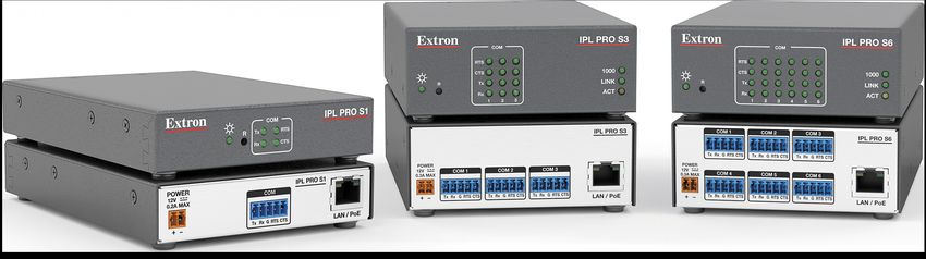
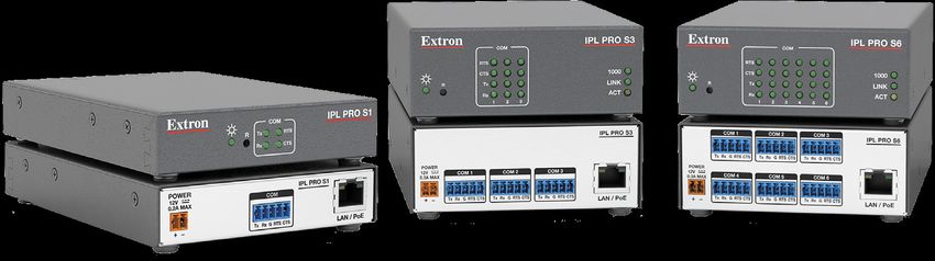
IPL Pro Series • Introduction 1About the IPL Pro Series
The IPL Pro Series Control Processors integrate Ethernet connection into AV systems to
allow users to remotely control, monitor, and troubleshoot AV equipment, including display
devices, switchers, source devices, and various other items such as lights, a projector lift,
or a screen motor. They can be used in a distributed control system environment or as
stand-alone control processors.
Figure 1. IPL Pro S1 (left), IPL Pro S3 (center), IPL Pro S6 (right)
Figure 2. IPL Pro CR88 (left), IPL Pro IRS8 (right)
An IPL Pro Series control processor is the centerpiece of a control system that features
Extron TouchLink Pro Touchpanels. The IPL Pro supports multiple TouchLink Pro touchpanels
over a standard Ethernet network. The touchpanels provide a convenient interface for
controlling the IPL, which, in turn, controls the other system components.
NOTE: GUI Designer is used to design the user interface layout of any Extron
TouchLink Pro touchpanel that is used with the IPL.
Use the Extron Toolbelt software to discover and manage the IPL Pro control processor
and other Extron control products. Configure the control processor using GC Professional
or GC Plus, or program it using Global Scripter (GS). Once you have set up how you want
it to work (set up IP addresses and functions, assigned drivers to ports, configured relays
and contact input), that information is saved to a project configuration file that is built and
uploaded into the IPL and to any optional TouchLink Pro touchpanels.
The IPL Pro Series integrates seamlessly with Extron GlobalViewer Enterprise software and
Extron Control for Web, iOS, and Android for remote control applications.
Features
General features
Flexible options for device control — The various IPL Pro models all offer TCP/Ethernet
control and monitoring, and, depending on the model, serial (RS-232) or infrared (IR)-based
control, relay device control, and event monitoring via contact input ports.
Rack mountability — The IPL Pro S1 has a 1 inch high, quarter rack wide enclosure, and
the other models are housed in a standard 1U high, quarter rack wide enclosure. They are
easily rack mounted or can be installed in or under furniture with an optional mounting kit.
IPL Pro Series • Introduction 2Support for Power over Ethernet (PoE) — The IPL supports power over Ethernet, which
allows the control processor to receive both power and an Ethernet connection over a single
connector.
Support for an external power supply — The IPL also supports connection to an
external 12 VDC power supply (included) that accepts 100-240 VAC, 50-60 Hz input.
Network and configuration features
• Global compatibility — The IPL uses industry standard Ethernet communication
protocols, including DHCP, DNS, HTTP, HTTPS, ICMP, NTP, SFTP, SMTP, SNMP, SSH,
TCP/IP, and UDP/IP.
• Embedded web pages — The IPL embedded web pages include online diagnostics
and monitoring of basic features.
• If the unit is configured to work with Extron Control, you can access the virtual user
interfaces from a link in the embedded web page.
• Remote equipment management — The IP Link Pro connection allows you
to remotely manage, monitor, and control several Ethernet-enabled products such
as projectors, cameras, video conferencing equipment, switchers, and other AV
equipment. The IPL provides support for the following:
• TCP, UDP, and HTTP connections
• Password protection using secure communication
• Up to 32 (GC Professional) or 8 (GC Plus) Ethernet devices at a time depending on
the configuration mode
• Connection via IP address or host name
• Multi-level password protection — This allows security to be set based on user
roles.
• System asset management — The configured system and control processor allow
you to control, monitor, and schedule various functions of devices in the system.
• E-mail notification — The IPL can be set up to send e-mail notifications, such as a
notice that a projector has been disconnected or the projector lamp has been used for
a designated number of hours.
• Additional security features — Each control processor can use the included Secure
Sockets Layer (SSL) certificate or a user-supplied, customized security certificate
(see Secure Sockets Layer (SSL) Certificates on page 31). IEEE 802.1X
Authentication is also supported in Extron devices once enabled. For details see IEEE
802.1X Certificates on page 32.
Feature Summary Table
The following table provides a summary of models and major features.
Features
Ports
IR/Serial
Contact
5-pole
Relay
Input
COM
Power IR
LAN
Model Mounting Supply Learning
IPL Pro S1 1 — — — 1 —
IPL Pro S3 3 — — — 1 —
External
IPL Pro S6 Rack 6 — — — 1 —
or PoE
IPL Pro IRS8 — 8 — — 1
IPL Pro CR88 — — 8 8 1 —
IPL Pro Series • Introduction 3Application Diagrams
The following figures show examples of types of devices that can be connected to some of
the ports on the IPL Pro Series control processors.
Flat Panel Display
MODEL 80
Extron
IPL Pro S1
IP Link Pro Control Processor
POWER
MAC: 00-05-A6-XX-XX-XX
IPL PRO S1
12V S/N: ####### E###### COM
0.2A MAX
Tx Rx G RTS CTS LAN / PoE
FLAT PANEL
HDMI with RS-232 Ethernet Extron
Embedded Audio /PoE TLP Pro 520M
5" Wall Mount
1
TouchLink Pro Touchpanel
Media Player Ethernet
Ethernet/
TCP/IP PoE
Network
Extron
Figure 3. An IPL Pro S1 Application
RS-232
RS-232
COM 1 COM 2 COM 3
IPL PRO S6
Extron IPL Pro S6 HDCP-
Compliant
MAC: 00-05-A6-XX-XX-XX
S/N: ####### E######
Tx Rx G RTS CTS Tx Rx G RTS CTS Tx Rx G RTS CTS
POWER
12V COM 4 COM 5 COM 6
IP Link Pro Control Processor
X.XA MAX
Displays
Tx Rx G RTS CTS Tx Rx G RTS CTS Tx Rx G RTS CTS LAN / PoE
Ethernet/PoE
Ethernet
Control
VLAN HDMI HDMI
RS-232
Ethernet/
Power
Power MEDIA I MEDIA II
Quantum
COMPLIANT
COMPLIANT
COMPLIANT
COMPLIANT
Injector
HDCP
HDCP
HDCP
HDCP
Elite
CONTROL
Control Ethernet/
Software Power IN IN IN IN IN OUT OUT
1 2 3 4 5 6 7 8 9 10 11 12 13 14 15
ATTENTION
OBSERVE PRECAUTIONS
FOR HANDLING
ELECTROSTATIC
SENSITIVE
DEVICES
Extron TLP Pro 1520TG WARNING
SEE USER GUIDE BEFORE
15" Tabletop
USING THIS EQUIPMENT
DO NOT REMOVE THIS PANEL
NO USER-SERVICEABLE
PARTS INSIDE
REFER ALL SERVICING TO
QUALIFIED SERVICE PERSONNEL
TouchLink Pro
THIS EQUIPMENT MUST BE
GROUNDED/EARTHED
DO NOT OBSTRUCT
VENTILATION GRILLES
DO NOT EXPOSE THIS EQUIPMENT
TO RAIN OR MOISTURE
Touchpanel
Extron Quantum Elite
Scalable Multi-Graphic
Composite or S-video Videowall Processor System
CCTV HDMI Blu-ray Player
Cameras RGB STANDBY/ON
PQLS HDMI OPEN/CLOSE FL OFF
USB
RGB HDMI DSS Receiver
PC
DVI HDMI DSS Receiver
PC
DVI
HDMI DSS Receiver
PC
PC
Figure 4. An IPL Pro S6 Application
IPL Pro Series • Introduction 4Device Control
The IPL must be configured in one of the following ways before it can send commands to a
projector, display, or other device:
• An IR, RS-232 or Ethernet driver file can be downloaded from the Extron website
(http://www.extron.com/download/index.aspx). The driver is saved to a folder and
commands from the driver are incorporated into the GC configuration file for the control
processor and any touchpanels that are selected to work with it. The configuration file is
built and uploaded to the IPL via GC.
• If a driver is not already available, RS-232 or Ethernet command strings can be
entered directly from a host computer using Global Configurator. These can then be
incorporated into controls within the GC project.
• For an IPL Pro IRS8, IR commands can be entered directly from an IR remote control
through IR learning. This can be done using IR Learner Pro to create a driver that
the control processor can use. IR learning is seldom needed, but it is convenient for
installing new or updated commands in the field in the rare cases when a driver is not
already available from Extron.
See the Global Configurator Help File (which is included with the software) for details
on setting up the IPL and for downloading, programming, or learning device control
commands.
About Global Configurator (with GC Professional and GC Plus Modes)
Global Configurator:
• Loads device drivers for monitoring the status of and controlling devices within the AV
system.
• Uploads GUI Designer interface layouts to touchpanels and third-party touch interfaces.
• Creates the configuration containing all the settings for the control processor and the
products with which it interacts in the AV system.
• Uploads the configuration to the control processor.
To obtain Extron control product software, you must have an Extron Insider account and
contact an Extron support representative. Extron provides training to our customers on how
to use the software. Access to the full set of features in Global Configurator Professional is
available to users who successfully complete Extron Control Professional Certification.
About Global Scripter
For those who prefer to program control systems rather than configure them, Extron offers
Global Scripter as an alternative to Global Configurator. Global Scripter is an integrated
programming development environment for Extron IP Link Pro, TouchLink Pro, and eBUS
products. It uses the object-oriented Python programming language and a custom Python
library called ControlScript. Global Scripter includes the ControlScript API as well as all of
the tools for developing control system programs, such as file management, code editing,
debugging and diagnostic tools. More information is available at http://www.extron.com/
technology/landing/programming/.
IPL Pro Series • Introduction 5PC System Requirements
To find the minimum hardware and software requirements for the PC you use to configure
the IPL Pro Series:
• Visit the Download page (http://www.extron.com/download/index.aspx) on the
Extron website and navigate to the web page for the specific software package (such
as Global Configurator and GUI Designer). Minimum PC hardware and software system
requirements are listed in the description section. In some cases, minimum device
firmware version requirements are also listed there.
• If system requirements are not listed on the software package web page, contact an
Extron support representative.
IPL Pro Series • Introduction 6Hardware Features
and Installation
This section covers the following material:
• Setup Checklist: How to Proceed With Installation — A checklist of tasks to guide
you through installation
• Network Communication Setup — A flowchart guide to network settings configuration
• Front Panel Features — Locations and some descriptions of items on the front panel
• Mounting the IPL Pro Series — Brief guidelines for mounting
• Rear Panel Features and Connections — Locations, descriptions, and cabling notes
for rear panel features and corresponding front panel indications
• Resetting the Unit — Information about the available reset modes and how to reset
the IPL
Pay careful attention to the order and types of setup tasks. Follow the setup checklist in this
guide or in the setup guide and keep it with you for reference throughout the installation and
configuration process.
Setup Checklist: How to Proceed With Installation
Get Ready
Familiarize yourself with the features of the control processor (see Front Panel
Features on page 11 and Rear Panel Features and Connections on page 13)
and of any TouchLink Pro touchpanels or button panels that are part of the system.
Download and install the latest version of the following:
Toolbelt software — for discovering the control processor and other control
products on the network, for managing core settings, and for upgrading firmware
when needed
Global Configurator (GC) software — for configuring the control system
Global Scripter software — for programming the control processor (as an
alternative to GC)
GUI Designer software — for designing layouts for Extron TouchLink Pro
touchpanels and third-party touch interfaces
IP Link Pro device drivers — for use with GC, to make control of other devices
possible
IR Learner Pro software — for use with models that have IR receiver ports, to
create your own IR drivers using the remote control of an AV device, if drivers are
not already available from Extron
All are available from www.extron.com (see Locating Software, Firmware, and
Driver Files on the Extron Website on page 26).
IPL Pro Series • Hardware Features and Installation 7Obtain network information for the unit from the network administrator. You need the
following details for each IP Link Pro device:
DHCP setting (on or off) Gateway IP address
Device (IPL Pro, TouchLink Pro, IPCP Pro) User name
IP address Passwords
Subnet mask
Write down the MAC address of each IP Link Pro device to be used.
Obtain model names and setup information for devices the IPL is going to control.
Each control processor comes with a factory-installed Secure Sockets Layer (SSL)
security certificate. If you intend to install a different SSL certificate, contact your IT
department to obtain the certificate or for instructions on how to obtain one. See
Secure Sockets Layer (SSL) Certificates on page 31 for requirements and
guidelines regarding SSL certificates.
For systems that are going to use IEEE 802.1X security, obtain a PEM-encoded security
certificate and private key (see IEEE 802.1X Certificates on page 32) from your IT
department.
Mount and Cable All Devices
Mount the unit to a rack or furniture (see Mounting the IPL Pro Series on page 12).
Cable devices to the control processor (see Rear Panel Features and Connections
starting on page 13).
Connect power cords and power on all the devices.
Set up the Control Processor, Touchpanels, and Network Button Panels for
Network Communication
Connect the PC to be used for setup, the control processor, and the touchpanels or
network button panels to the same Ethernet subnetwork. For control processor LAN
connections, see LAN/PoE (IP) connectors and LEDs on page 17.
Start Toolbelt and use it to set the IP address, subnet, gateway IP address, DHCP
status, and related settings (see the flowchart in Network Communication Setup on
page 10).
NOTE: When setting up DHCP during network configuration or if using a host
name instead of an IP address, the user must enter a qualified host name
(Username.HostName.Domain). For example: somename.extron.com.
IPL Pro Series • Hardware Features and Installation 8Configure or Program the Control Processor, Touchpanels, and Network
Button Panels
If TouchLink Pro touchpanels are part of the system, start and use GUI Designer
to design, save, and build the graphical user interface (GUI) layout for the
touchpanels (see the GUI Designer Help File for instructions).
NOTE: To redeem (activate) a LinkLicense, go to www.extron.com/llredeem and
follow the online instructions.
Using GC, create a new GC Professional or GC Plus project and configure the
control processor and other IP Link Pro devices. The configuration tells the control
processor:
• How its ports function • What to monitor
• How to control other products • When to do things
• Which touchpanels to interact with • Whom to notify, how, and under what
circumstances
Configure ports on the control processor.
Select device drivers and link them to each serial, IR/serial, or Ethernet port.
Select settings (serial protocol, relay behavior, contact input behavior) as
needed.
Add Network Button Panels (NBPs) and set them up. Assign button functions as
desired.
Set up monitors, schedules, macros, and local variables.
Add touchpanels and set them up:
Upload the GUI configuration to the Global Configurator project.
Assign any appropriate functions, monitors, or schedules to the touchpanels
and their buttons.
If not using GC Professional or GC Plus, use Global Scripter to program the
control system as desired.
Program ports on the control processor.
Program each serial, IR/serial, or Ethernet port.
Program relay behavior and contact input settings as needed.
Add Network Button Panels (NBPs) and set them up. Assign button functions as
desired.
Add touchpanels and set them up:
Upload the GUI configuration to the Global Configurator project.
Program functions, monitors, or schedules to the touchpanels and their
buttons.
Save the project.
Build and upload the system configuration to the control processor and other system
devices.
Test and Troubleshoot
Test the system. See the Troubleshooting section starting on page 29 for an outline
of items to check during system troubleshooting.
Make adjustments to wiring or configuration as needed.
IPL Pro Series • Hardware Features and Installation 9Network Communication Setup
Network setup is essential prior to configuration. Use the flowchart as a guide to setting up
the control processor for network use..
Network Communication Setup
Connect the PC and the LAN port of the
control processor to the same network.
Apply power to all devices.
Open the Toolbelt software from within
Global Configurator (GC Professional or GC Plus mode)
or as the stand-alone application.
Start Device Discovery.
Toolbelt displays a list of all Extron control devices
connected to the network.
NOTE: If using
Using the MAC address, locate the desired device 802.1X security, see
in the list and select it.
the Extron 802.1X
Technology Reference
Use the Set IP feature in Toolbelt or Guide and the
use the Toolbelt Manage > Network Settings tab
feature to enter the IP address and subnet address, Toolbelt Help file for
then configure other network settings as needed. additional details on
system setup.
Network Setup
IPL Pro Series • Hardware Features and Installation 10Front Panel Features
Examples of front panel features COM
IPL PRO S1
are shown at right. The Power R
Tx RTS
quantity and location of ports LED Rx CTS
and corresponding front panel
LEDs differ among IPL models. Reset COM (Serial)
Button LEDs
However, the functions of each (recessed)
type of port and their LEDs are
identical for all models.
IPL PRO S3
Most of the features COM
and LED indications are RTS
CTS 1000
described and shown in Power R Tx LINK
LED
the Rear Panel Features Rx
1 2 3
ACT
and Connections section
starting on page 13 paired
with the descriptions of the Reset COM (Serial) LAN/
Button LEDs Network
corresponding rear panel (recessed) LEDs
ports.
NOTE: See the Software- COM
IPL PRO S6
based Configuration RTS
and Control section CTS 1000
Power
starting on page 24 and LED
R Tx LINK
Rx ACT
the Global Configurator 1 2 3 4 5 6
Help File and Toolbelt
Help File for information
about Global Configurator Contact Input Relay
LEDs LEDs
and Toolbelt, which you
must use to set up the
unit. IPL PRO CR88
INPUT RELAYS
1 5 1 5
2 6 2 6 1000
Power R 3 7 3 7 LINK
Reset Features LED 4 8 4 8 ACT
Reset button and LED —
Pressing this recessed button
Reset LAN/
causes various product Button IR/Serial IR Learning Network
settings to be reset to the (recessed) LEDs Receiver LEDs
factory defaults. The green
power LED blinks depending IPL PRO IRS8
on the selected reset mode IR/SERIAL
1 5
(see Resetting the Unit on 2 6 1000
page 21 and the reset Power R 3 7 IR LINK
LED
modes table on page 21 4 8 ACT
for details).
NOTE: Numbers adjacent to LEDs
correspond to the like-numbered
rear panel ports.
Figure 5. IPL Pro Series Front Panels
IPL Pro Series • Hardware Features and Installation 11IR Learning Receiver
In most cases, Extron has already produced a driver file for controlling the projector, display,
or source device you plan to use. If a device driver file is not available, you can create your
own using Extron IR Learner Pro software, the remote control of the projector or display,
and the IR learning receiver sensor on the IPL, shown below.
IR
This receiver accepts infrared signals of from 30 kHz to 300 kHz. IR Receiver
The IR remote control must be pointed directly at the receiver IR Learning Angle
for best results. The diagram at right indicates the best and Distance
distances and angles at which to hold the remote control.
2–12"
(4–30 cm)
1 2 3
4 5 6
7 8 9
0
Mounting the IPL Pro Series
Mounting Options
Optional 1U high rack shelves and a variety of rack mounting bracket kits and furniture
mounting kits are available for use with the IPL. The 1 inch high model (IPL Pro S1) requires
different brackets than the 1U high models. Visit the product-specific page on the Extron
website (www.extron.com) for a list of compatible accessories for mounting your control
processor or call a support representative to find out which kit to order for your installation.
Read the instructions that are included with the rack shelf or mounting kit for installation
procedures and see the UL rack mounting guidelines.
UL Rack Mounting Guidelines
The following Underwriters Laboratories (UL) guidelines pertain to the safe installation of
the IPL Pro Series in a rack.
1. Elevated operating ambient temperature — If installed in a closed or multi-unit rack
assembly, the operating ambient temperature of the rack environment may be greater
than room ambient temperature. Therefore, install the IPL in an environment compatible
with the maximum ambient temperature (Tma = +122 °F, +50 °C) specified by Extron.
2. Reduced air flow — Install the equipment in a rack so that the amount of air flow
required for safe operation of the equipment is not compromised.
3. Mechanical loading — Mount the equipment in the rack so that a hazardous
condition is not achieved due to uneven mechanical loading.
4. Circuit overloading — Connect the equipment to the supply circuit and consider the
effect that circuit overloading might have on overcurrent protection and supply wiring.
Appropriate consideration of equipment nameplate ratings should be used when
addressing this concern.
5. Reliable earthing (grounding) — Maintain reliable grounding of rack-mounted
equipment. Pay particular attention to supply connections other than direct connections
to the branch circuit (such as use of power strips).
IPL Pro Series • Hardware Features and Installation 12Rear Panel Features and Connections
ATTENTION:
• Installation and service must be performed by experienced personnel.
• L’installation et l’entretien doivent être effectués par du personnel expérimenté.
The quantity of ports and corresponding front panel LEDs differs among IPL models, but the
functions of each type of port and their LEDs are identical for any model that includes that
type of port.
A D B
POWER
MAC: 00-05-A6-XX-XX-XX
IPL PRO S1 INPUT RELAYS IPL PRO CR88
12V S/N: ####### E###### COM
C D
0.2A MAX MAC: 00-05-A6-XX-XX-XX
S/N: ####### E######
1 2 3 4 G 1 2 3 4
Tx Rx G RTS CTS POWER
LAN / PoE
12V
0.3A MAX
C
IPL PRO S3 5 6 7 8 G 5 6 7 8 LAN / PoE
MAC: 00-05-A6-XX-XX-XX
D
00-05-A6-XX-XX-XX
MAC: 00-05-A6-XX-XX-XX
S/N: ####### E######
S/N: ####### E######
POWER
12V COM 1 COM 2 COM 3 A E F
C
0.3A MAX
Tx Rx G RTS CTS Tx Rx G RTS CTS Tx Rx G RTS CTS LAN / PoE
A B
COM 1 COM 2 COM 3
IPL PRO S6 IPL PRO IRS8
MAC: 00-05-A6-XX-XX-XX
D MAC: 00-05-A6-XX-XX-XX
D
00-05-A6-XX-XX-XX
S/N: ####### E###### MAC: 00-05-A6-XX-XX-XX
S/N: ####### E######
S/N: ####### E######
Tx Rx G RTS CTS Tx Rx G RTS CTS Tx Rx G RTS CTS
POWER POWER
12V COM 4 COM 5 COM 6 12V IR/SERIAL
C C
0.3A MAX 0.3A MAX 1 2 7 8 7 8 7 8
Tx Rx G RTS CTS Tx Rx G RTS CTS Tx Rx G RTS CTS LAN / PoE S G S G S G S G S G S G S G S G LAN / PoE
A G
Figure 6. IPL Pro Series Rear Panels
A Power input connector (external power supply), page 14 E Contact input ports, page 18
B 5-pole COM ports (RS-232/RS-422*/RS-485*), page 33 F Relay ports, page 19
C LAN connectors and LEDs (Ethernet), page 17 G IR/serial output ports, page 20
D MAC address, page 17
IPL Pro Series • Hardware Features and Installation 13Power Connections
A Power input connector (external power supply) — Connect the IPL to the
included 12 VDC, 0.5 A power supply via this port (see figure 7 on page 13), then
connect the external power supply to a 100 to 240 VAC power source.
POWER
12V
X.XA MAX Power Input, External Power Supply R
• Connect to • Front panel LED ( ) blinks during
included 12 VDC boot-up and remains lit when the
power supply. IPL is powered and operational.
Rear Front Panel
Panel
3/16" Ground all devices. NOTE: Check
(5 mm)
To the polarity
Max. AC
Ridged of the power
power
– Return supply before
+12 VDC input connecting it
Tie Wrap External 12 VDC
Smooth Power Supply to the IPL.
Smooth Ridged
Figure 7. Connecting an External Power Supply
ATTENTION:
• Always use a power supply supplied or specified by Extron. Use of an
unauthorized power supply voids all regulatory compliance certification and may
cause damage to the supply and the unit.
• Utilisez toujours une source d’alimentation fournie par Extron ou recommandée.
L’utilisation d’une source d’alimentation non autorisée annule toute certification
de conformité réglementaire et peut endommager la source d’alimentation ainsi
que l’unité.
• If not provided with a power supply, this product is intended to be supplied by a
UL Listed power source marked “Class 2” or “LPS” and rated output
12 VDC, minimum 0.5 A, or 48 VDC (PoE), minimum 0.35 A.
• Si le produit n’est pas fourni avec une source d’alimentation, il doit être alimenté
par une source d’alimentation certifié UL de classe 2 ou LPS, avec une tension
nominale 12 Vcc, 0.5 A minimum ou 48 Vcc (PoE) minimum, 0.35 A minimum.
• Unless otherwise stated, the AC/DC adapters are not suitable for use in air
handling spaces or in wall cavities.
• Sauf mention contraire, les adaptateurs CA/CC ne conviennent pas à une
utilisation dans les espaces d’aération ou dans les cavités murales.
• The installation must always be in accordance with the applicable provisions of
National Electrical Code ANSI/NFPA 70, article 725 and the Canadian Electrical
Code part 1, section 16. The power supply shall not be permanently fixed to a
building structure or similar structure.
• Cette installation doit toujours être conforme aux dispositions applicables
du Code américain de l’électricité (National Electrical Code) ANSI/NFPA 70,
article 725, et du Code canadien de l’électricité, partie 1, section 16. La source
d’alimentation ne devra pas être fixée de façon permanente à une structure de
bâtiment ou à une structure similaire.
IPL Pro Series • Hardware Features and Installation 14NOTE: The IPL Pro Series control processors accept power over Ethernet (PoE)
through the LAN/PoE port (see figure 7, C on page 13) in addition to network
communication (see the cabling and details information on page 17). Both
an external power supply and PoE can be connected to the control processor
simultaneously. The IPL uses PoE when it is available but can switch seamlessly to
the external 12 VDC power supply if the PoE connection is dropped.
ATTENTION:
• Power over Ethernet (PoE) is intended for indoor use only. It is to be connected
only to networks or circuits that are not routed to the outside plant or building.
• L’alimentation via Ethernet (PoE) est destinée à une utilisation en intérieur
uniquement. Elle doit être connectée seulement à des réseaux ou des circuits
qui ne sont pas routés au réseau ou au bâtiment extérieur.
IPL Pro Series • Hardware Features and Installation 15Bidirectional Control and Communication Connections and Features
B 5-pole COM ports, RS‑232/RS-422*/RS-485* (see figure 7, on page 13) —
Use COM ports for serial control of a display
or other device and to receive status messages
from the connected devices. These ports can 3/16" TIP: STP 20-2P
send commands from a driver file. RS-232 is (5 mm)
Max.
cable, shown
at left, is
the default mode of operation. 7/8"
(22 mm)
recommended
IPL Pro Series serial protocol: for these
Heat Shrink connections.
• 300 to 115200 baud (9600 baud = default) on Outer
Jacket to For best
Inner results,
• 8 (default) or 7 data bits Conductor
Transition insulate the
• 1 (default) or 2 stop bits common or
drain wires
• No parity (default), even, or odd parity using heat
Extron shrink.
• Flow control support (default = none): STP 20-2P Cable
hardware and software (XON, XOFF)
*Supported serial formats vary depending on Serial Options
the model and the COM port, as shown at Model COM Port
RS-232 RS-232, RS-422,
or RS-485
Only
right. IPL Pro S1 1
IPL Pro S3 1
Use the following diagram as a wiring guide to IPL Pro S6
2, 3
1
cable the IPL to other devices. 2, 3, 4, 5, 6
Rear Panels Front Panels
COM 1 Serial (COM) Ports
COM
5-pole COM Select protocol via software.
Tx Rx G RTSCTS
(RS-232, RS-422*, RS-485*) COM port default protocol: RTS
*See the Serial Options
table for which port • 9600 baud CTS
COM 4
supports which standards. • 8 data bits • 1 stop bit Tx
• no parity • no flow control
Rx
1 2 3 4 5 6
Tx Rx G RTSCTS
NOTE: The 5-pole COM ports support both
hardware and software flow control. RTS = Request to Send
CTS = Clear to Send
Tx = Transmitting Data
COM
Rx = Receiving Data
Tx
Tx RTS
Rx
R CTS
CTS Clear to send Projector, Panel 5-pole COM Pin Configurations
To 5-pole RTS Request to send Display, PC, or
G Ground Other RS-232, Pin RS-232 RS-422* RS-485*
COM port Rx Receive Receive (Rx) RS-422, or Data-
Tx Transmit Transmit (Tx) RS-485 Device 1 (Tx) Tx Tx-
(pins 1 & 2
Heat Shrink Heat Shrink Strip wires 2 (Rx) Rx Rx- tied together)
Over Shield Wires 3/16" (5 mm)
max. 3 (G) Ground Ground Ground
4 (RTS) RTS Tx+ Data+
(pins 4 & 5
NOTE: If you use cable that has a drain wire, tie the drain wire to ground at both ends. 5 (CTS) CTS Rx+ tied together)
*See the Serial Options table of supported
formats for each port.
Figure 8. Wiring COM ports for Serial Control
For bidirectional serial communication, the transmit, ground, and receive pins must be
wired at both the IPL Pro Series and the other device. Each projector or other device
may require different wiring. For details, see the manual for that equipment or read the
Extron device driver communication sheet, which is included with the drivers.
NOTE: Maximum distances between the IPL and the device being controlled are
generally up to 200 feet (61 m) but may vary based on factors such as cable
gauge, baud rates, environment, and output levels (from the IPL and the device
being controlled).
IPL Pro Series • Hardware Features and Installation 16C LAN/PoE (Ethernet) connectors and LEDs — To connect the IPL to an Ethernet
network (so you can configure and control the IPL and the devices connected to it),
plug a cable into the LAN RJ-45 socket (see figure 7 on page 13) and connect the
other end of the cable to a network switch, hub, router, or PC connected to a LAN or
the Internet. For details of communication protocols, ports, and services used, see the
Pro Series Control Product Network Ports and Licenses Guide at www.extron.com.
The IPL Pro Series control processors accept power over Ethernet (PoE) through the
LAN port (see the Power over Ethernet (PoE) Attention statement on page 15).
Both an external power supply and PoE can be connected to the control processor
simultaneously. The IPL uses PoE when it is available but can switch seamlessly to the
external power supply if the PoE connection is dropped.
Cabling:
• For 10Base-T (10 Mbps) networks, use a CAT 3 or better cable.
• For 100Base-T (max. 155 Mbps) or 1000Base-T networks, use a CAT 5 or better cable.
You must configure this port before using it. Configure the settings via Global
Configurator. See Software-Based Configuration and Control starting on
page 24 of this guide for basic information on configuration.
Activity LED (connector and front panel) — This yellow LED blinks to indicate network
activity.
Link LED (connector and front panel) — This green LED lights to indicate a good
network connection.
1000 LED (front panel) — This green LED lights when the unit is connected to a gigabit
network connection.
TCP/IP Extron Devices
PC Network (Switchers, Scalers)
Touchlink Pro
Touchpanel
Ethernet
Insert Twisted
Pair Wires
NOTES:
• The factory configured passwords for this device
have been set to the device serial number.
Passwords are case sensitive. Performing a Reset
RJ-45 to Factory Defaults reset (see Resetting the Unit
Connector
on page 21) sets the passwords to extron.
• DHCP is off by default.
Pins:
87654321
IPL PR
PRO S6 LAN/PoE (Ethernet)
Default protocol: Power over Ethernet (PoE):
5-A
A6-XX-XX-XX
5--A66-XX-XX-XX
#### E######
• IPL IP address: 192.168.254.250 If PoE is available, the IPL uses PoE. 1000 Mbps
Activity Link Connection
LED LED • Gateway IP address: 0.0.0.0 If PoE is dropped (disconnects), the 1000
• Subnet mask: 255.255.255.0 IPL switches seamlessly to the Network is
• DNS address: 127.0.0.1 external 12 VDC power supply, if it LINK active.
• DHCP: off is installed. ACT
• Link speed and duplex level: Default login credentials: Data is being
LAN / PoE sent/received.
autodetected • Username: admin or user
• Data rates: 10/100/1000Base-T • Password: extron
Rear Panel Front Panel
Figure 9. LAN Connector and LEDs
D MAC address — This is the unique user hardware ID number MAC
Address
(Media Access Control [MAC] address) of the unit (for example, MAC: 00-05-A6-XX-XX-XX
00-05-A6-05-1C-A0). You may need this address during S/N: ####### E######
configuration.
IPL Pro Series • Hardware Features and Installation 17Unidirectional Control and Communication Connections
E Input (contact closure input) ports (see figure 7 on page 13) — To allow the
IPL to monitor devices to trigger events, connect a switch, sensor, or similar item to one
of these ports. Wire the ports as shown below.
Rear Panel Input (Contact closure input) Front Panel
INPUT
Each port senses external switch or contact closure by using a
1k ohm pull-up resistor in a TTL (5 VDC) circuit.
INPUT
Use these ports to monitor or trigger events and functions
1 2 3 4 G (toggle relays, issue commands, send e-mail), once configured. 1 5
2 6
3 7
4 8
5 6 7 8 G
Heat
Shrink
Over Input LEDs
Shield Light when the
Wires Ground corresponding
Share the same ground ports are active
Wire among contact input (tied to ground,
Nut logic low).
connections.
Device 4
G Switch, Device 3 (Switches, sensors,
4 Sensor relays, or similar
3 Device 2 items)
2
1 Device 1
Figure 10. Wiring the Contact Input Ports
A 1k ohm pull-up resistor in a TTL (5 VDC) circuit senses external switch or contact
closure. After these ports have been configured, when the circuit between a signal
pin and a ground pin is closed, each port can trigger events (such as toggling relays,
issuing commands, or sending an e-mail).
• When an external switch closes (shorts to ground, logic low), the port is on and the
front panel LED is on.
• When the external switch opens (logic high), the port is off. The front panel LED is
off.
• Example application: connecting a two-position switch
+5.0 V
1k ohms
Two-position
Switch
SW 2
Contact
Input
CTL
Voltage
SW 1 Protection
GND
Figure 11. Contact Input Application: Two-position Switch With Pull-up
Two-position switch is open: logic high, front panel LED is off.
Two-position switch is closed: logic low, front panel LED is lit.
IPL Pro Series • Hardware Features and Installation 18F Relay ports — Relay ports (see figure 7 on page 13) provide control for power,
screen or projector lifts, window coverings, and similar items, when trigger events occur.
Rear Panel Front Panel
RELAYS
RELAYS
1 2 3 4 Relays 1 5
• Connect devices for relay control. 2 6
• Do not exceed a total of 24 V at 1 A for each port. 3 7
4 8
5 6 7 8
Relay LEDs
Normally
Open
Common
Light when the
corresponding relays
All relays are are activated (tied to
normally open. GND, closed).
To Room Control
Equipment
Figure 12. Cabling Relay Ports
These relay contacts may be used to control any equipment as long as the contact
specifications of a total of 24 V at 1 A are not exceeded for each port. These relays are
normally open by default.
When activated, the open contacts close. They can be set up to operate in one of two ways:
• Latching (brief or indefinite period contact) (press to close, press to open), or
• Pulsed (timed cycle) (press to close, timeout to open, with automatic repeat).
In pulse mode the default timeout period (hold time) is ½ second (500 ms). Use Global
Configurator to change the length of the timeout period.
NOTE: The pulse function is absolute: it always sets the relay state to closed, times
out (briefly), then opens the contact. It overrides the previously selected setting (on
state, off state, or toggle).
IPL Pro Series • Hardware Features and Installation 19G IR/serial output ports (see figure 7 on page 13) — An IPL Pro Series controller
with these ports can use infrared signals or unidirectional RS‑232 serial signals to
control various devices (up to four per port for IR) via these ports. Set output signal type
(IR or serial) during configuration. The figure below shows wiring examples.
Rear Panel Front Panel
IR/Serial Ports
Output options:
IR/SERIAL
• IR (30 kHz to 300 kHz,
with or without carrier signals) 1 5
• Unidirectional RS-232 2 6
IR/SERIAL
1 2 7 8 7 8 7 8 3 7
4 8
S G S G S G S G S G S G S G S G
IR/S LEDs
Light when signals are transmitted
or on the corresponding IR/serial port.
3/16"
(5 mm)
max. (-)
To a Projector,
Panel Display, (+) To the IR Receiver of a
IR or RS-232 (-) Projector, Display, or
or the Wired G Ground (-)
IR Remote or
Output Source Device
Ground S IR Output
RS-232 Port of Unidirectional (+) (+)
a Source Device IR Two Single IR Emitters
Figure 13. Wiring the IR/Serial Ports
Serial control — Connect one of these ports to the serial control receive (Rx) and
ground pins of the device to be controlled. These ports have the same serial protocol
options (see page 16) as the COM ports.
IR control — Connect one of these ports directly to the wired IR port of another device.
Alternatively, insert the wires from up to four IR Emitters into an IR port and place the
heads of the emitters over or next to the IR signal pickup windows of the devices. For
wiring, see the following diagrams or the IR Emitter Installation Guide (available on
www.extron.com).
NOTE: Each emitter must be within 100 feet (30.4 meters) of the IPL for best
IR control results.
Installing One Single Emitter Installing One Dual Emitter
Ground (−) Ground (−)
IR Signal (+) IR Signal (+)
One Single IR Emitter Dual IR Emitter
Installing Two Single Emitters
When installing only single emitters, tie them in series as shown below.
Ground (−)
(−)
(+)
IR Signal (+) (−)
(+)
Two Single IR Emitters
IPL Pro Series • Hardware Features and Installation 20Resetting the Unit
There are four reset modes that are available by pressing the
Reset button on the front panel. The Reset button is recessed, so use
a pointed stylus, ballpoint pen, Extron Tweeker, or small screwdriver to
access it. See the reset modes table below and on the next page for a
summary of the modes. R
ATTENTION:
• Review the reset modes carefully. Using the wrong reset mode
may result in unintended loss of flash memory programming, Power Reset
LED Button
port reassignment, or a unit reboot.
• Analysez minutieusement les différents modes de
réinitialisation. Appliquer le mauvais mode de réinitialisation
peut causer une perte inattendue de la programmation
de la mémoire flash, une reconfiguration des ports ou une
réinitialisation de l’unité.
NOTE: If you hold down the Reset button continuously, the LED blinks every
3 seconds, and the unit enters a different mode, from the Reset all IP Settings mode
through the Reset to Factory Defaults mode. For Reset to Factory Defaults mode
the LED blinks three times, the third blink indicating the last mode. The modes are
separate functions, not a continuation from one mode to the next.
IPL Pro Series Control Processor Reset Mode Summary
Use This Activation Result
Mode
Mode to...
Temporarily To start the Use Factory Firmware reset mode and replace The control processor reverts to the
boot up the firmware: factory default firmware. Event scripting
unit with 1. On the control processor, hold down the recessed Reset does not start if the unit is powered on in
factory- button while applying power to the unit. Keep holding the this mode. All user files and settings such
Use Factory Firmware
installed button down until the Power LED blinks twice, then release as drivers, adjustments, and IP settings are
firmware for a the button. The LED blinks slowly during bootup. The control maintained.
single power processor enters factory firmware mode.
cycle in the NOTE: To return the unit to the firmware
event that 2. Upload new firmware to the unit as desired (see Updating version that was running prior to the
a firmware the Firmware on page 35 for details). reset, cycle power to the unit.
update has NOTE: Do not continue to operate the IPL Pro control
failed or if
processor using the factory firmware version. If you want to
incompatibility
issues arise use the factory default firmware version, you must upload
with user- that version again. See the Global Configurator Help File or
loaded Toolbelt Help File for firmware upload instructions.
firmware
IPL Pro Series • Hardware Features and Installation 21IPL Pro Series Control Processor Reset Mode Summary
Use This Activation Result
Mode
Mode to...
Recover For devices with firmware version 1.04 and lower
project
configuration To start the Project Recovery reset mode and recover a project: Project Recovery mode stops regular
and program 1. On the PC, open Global Configurator. operation and allows a connection to be
files if made to the unit via GC software without
passwords 2. Click the Tools menu and select Project Recovery. The requiring password entry so that project
have been lost Recovery Mode dialog box opens. files can be retrieved and saved.
3. Enter the IP address or host name of the target device for
which you want to perform project recovery. • During product recovery mode, events are
stopped, and so is communication with AV
4. Click Recover. The software allows indefinite time to devices.
establish a connection (until a connection is made or the user
clicks Cancel). • While the control processor is in this mode,
use the GC software to recover project
5. On the control processor, hold down the recessed Reset files.
button while applying power to the unit. Hold the button down
until the Power LED blinks twice, then release the button. • If the software does not initiate project
The control processor enters project recovery mode for recovery within 30 seconds after the
20 seconds, during which time the Power LED blinks quickly. control processor enters this mode, the
GC automatically connects to the control processor, then control processor exits recovery mode.
opens and retrieves the project from the unit. • Upon exiting project recovery mode:
6. Cycle power to the control processor to exit project recovery • The unit returns to its pre-recovery
mode. mode state and settings.
7. Perform the Reset to Factory Defaults reset on the control • The Power LED returns to being
processor. steadily lit.
8. Open Toolbelt, start device discovery, select the desired
control processor from the list and click Manage.
9. Click the Network Settings tab and set the IP address of
the control processor.
10. Click the User Management tab and change the passwords
of the control processor.
Project Recovery
11. Close Toolbelt.
12. In GC, add the new passwords to the recovered project.
13. Save the project.
14. Upload the project from GC to the control processor.
For devices with firmware version 1.05 and higher
To start the Project Recovery reset mode and recover a project: Project Recovery mode stops regular
1. On the PC, open Global Configurator. operation and allows a connection to be
made to the unit via GC software without
2. Click the Tools menu and select Project Recovery. The requiring password entry so that project
Recovery Mode dialog box opens. files can be retrieved and saved.
3. Enter the IP address or host name of the target device for
which you want to perform project recovery. • During project recovery mode, events are
stopped, and so is communication with AV
4. Click Recover. The software allows indefinite time to stablish devices.
a connection (until a connection is made or the user clicks
Cancel). • While the control processor is in this mode,
use the GC software to recover project
5. On the control processor, press the Reset button three files.
times within one second. The control processor enters
project recovery mode for 30 seconds, during which time the • If the software does not initiate project
Power LED blinks quickly. recovery within 30 seconds after thecontrol
processor enters this mode, the control
GC automatically connects to the control processor, then processor exits recovery mode.
opens and retrieves the project from the unit.
• Upon exiting project recovery mode:
6. Perform the Reset to Factory Defaults reset on the control
processor. • The unit returns to its pre-recoverymode
state and settings.
7. Open Toolbelt, start device discovery, select the desired
• The Power LED returns to being
control processor from the list and click Manage.
steadily lit.
8. Click the Network Settings tab and set the IP address of
the control processor.
9. Click the User Management tab and change the passwords
of the control processor.
10. Close Toolbelt.
11. In GC, add the new passwords to the recovered project.
12. Save the project.
13. Upload the project from GC to the control processor.
IPL Pro Series • Hardware Features and Installation 22You can also read