SECURE BOOT OF ZYNQ-7000 SOC - AUTHOR: ED PETERSON - XILINX
←
→
Page content transcription
If your browser does not render page correctly, please read the page content below
Application Note: Zynq-7000 SoC

                                     Secure Boot of Zynq-7000 SoC
                                     Author: Ed Peterson
XAPP1175 (v2.2) January 14, 2021

Summary
           The Zynq®-7000 SoC integrates a system on-chip (SoC) and programmable logic (PL). The boot
           mechanism, unlike previous Xilinx®devices, is processor driven. This application note shows
           how to boot the Zynq device securely using Quad Serial Peripheral Interface (QSPI) and secure
           digital (SD) modes. The optimal use of authentication and encryption for different security
           requirements is described. A method of handling private keys securely is provided. Multiboot
           examples show how to boot a golden image if the boot of an image fails. Examples show how
           to generate and program keys. Applications using Zynq security features are discussed.

           Download the reference design files for this application note from the Xilinx website. For
           detailed information about the design files, see Reference Designs.

Introduction
           To protect your valuable intellectual property (IP), it is important to always securely boot fielded
           Zynq devices—especially because the incremental effort and cost to boot securely is relatively
           small. Secure boot of Zynq devices uses Advanced Encryption Standard (AES) symmetric and
           Rivest, Shamir, Adleman (RSA) asymmetric cryptographic algorithms. This application note
           provides the concepts, tools, and methods to implement a secure boot. It shows how to create
           a secure embedded system, and how to generate, program, and manage the AES symmetric
           secret key and the RSA asymmetric private/public key pair.

           To build and boot a secure embedded Linux system quickly, skip to the section Booting the TRD
           Securely, and use the zc702_linux_trd reference design (TRD) system. Secure boot does not
           require programmable logic (PL) resources which are otherwise available to the user. The boot
           time of a secure Linux system is approximately the same as a non-secure system.

XAPP1175 (v2.2) January 14, 2021                                                                              1
                                               www.xilinx.com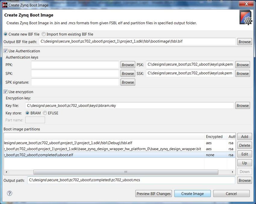
Introduction

          How to Read this Document
          Figure 1 shows the secure boot topics discussed.
          X-Ref Target - Figure 1

                                              Zynq Security Components

                                            Quickly Building and Booting
                                           a Secure Embedded Linux System

                                          Creating Secure Embedded Systems

                                             Generating and Programming
                                                Cryptographic Keys

                                          Advanced Key Management Options

                                        Secure Embedded Systems Applications

                                                                  XAPP1175_01_070813

                                          Figure 1:    Topics in Secure Boot
          The Boot Architecture, Boot Process, AES Encryption and RSA Authentication, Security in
          Embedded Devices, and Secure System Development sections provide background information
          on Zynq secure boot. Users familiar with booting Zynq devices on the zc702 board can skip to
          the Booting the TRD Securely section and quickly boot the zc702_linux_trd system.

          The Building and Booting a Secure System section shows new users how to build and boot a
          secure system using the Xilinx graphical user interface (GUI). The system built is not used in
          other sections, so readers experienced with Xilinx tools can skip this section.

          The Secure Boot Image Considerations section shows how to build custom secure embedded
          systems. A wide variety of use cases are supported.

          The Generating and Programming Keys section shows how to create AES and RSA keys, and how
          to program the control functions and keys into Zynq devices for a secure embedded system.

          The Advanced Key Management Options section shows how to protect RSA keys.

          The Secure Embedded Systems Applications provides examples using the included reference
          systems. The Multiboot section develops systems which combine security and multiboot. The
          zc702_data system shows how to load data into Zynq devices securely. The zc702_jtag_en
          system discusses the use of JTAG after a secure boot.

XAPP1175 (v2.2) January 14, 2021                                                       Send Feedback
                                                                                                           2
                                             www.xilinx.com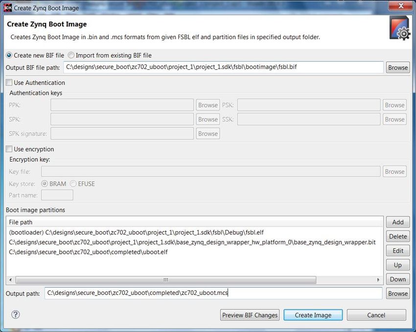
Hardware and Software Requirements

Hardware and Software Requirements
          The hardware requirements for the reference systems are as follows:

          •   ZC702 Evaluation Board with Revision C xc7020 silicon
          •   AC Power Adapter (12 VDC)
          •   USB Type-A to USB Mini-B Cable (for UART communication)
          •   Xilinx Platform Cable or Digilent USB Type-A to USB Micro B cable for programming and
              debugging using JTAG
          •   Secure Digital Multimedia Card (SD) flash card
          •   Ethernet cable to connect the target board with host machine (optional)
          •   Xilinx Software Development Kit 2014.4 (or later)
          •   Xilinx Vivado® Design Suite 2014.4 (or later)

Boot Architecture
          This section provides an overview of the hardware and software components used in the boot
          process.

          Hardware Components Used in Boot
          The two functional blocks in Zynq devices are the processing system (PS) and programmable
          logic (PL). The PS contains dual Arm® Cortex™-A9 MPCores and ten (x2) hard IP peripherals.
          The PL is derived from Xilinx® 7 series FPGA technology.

          The hardware components used to boot are the CPU, system level control register (SLCR),
          non-volatile memory (NVM), secure storage, JTAG, AES/HMAC, on-chip memory (OCM), dual
          data rate random access memory (DDR), and BootROM. Figure 2 is a diagram of the hardware
          components used in boot. The NVM and DDR memory are off chip. Booting typically uses only
          one NVM type.

XAPP1175 (v2.2) January 14, 2021                                                Send Feedback
                                                                                                       3
                                             www.xilinx.com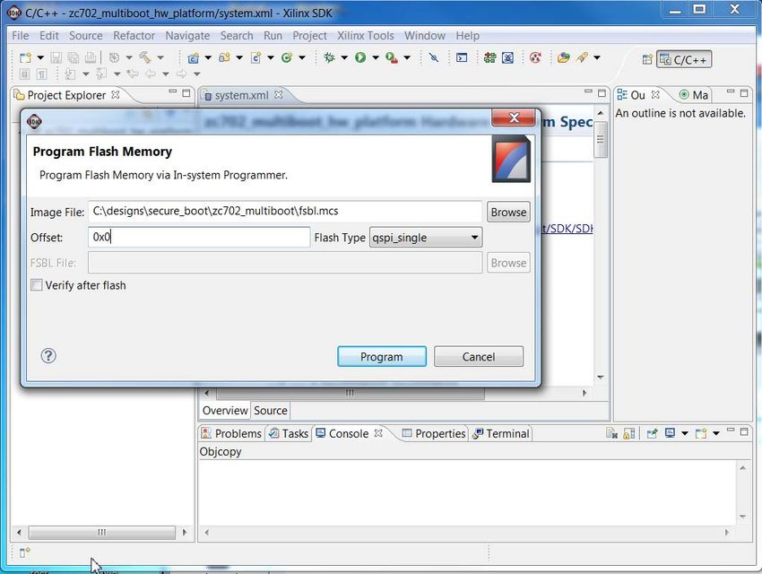
Boot Architecture

          X-Ref Target - Figure 2

                                                                                      Processing System
                                                     eFUSE                                 Boot
                                                   SHA256(PPK)            CPU
                                                                                           ROM                  DAP

                                                    Controllers
                                       SD              SD                 SLCR
                                      NAND            NAND                                  DDR
                                                                                          Controller                  DDR
                                      NOR              NOR
                                                                          OCM
                                      QSPI            QSPI

                                                            Device Configuration Interface
                                                                          AXI
                                                            Secure                 DMA
                                                             Vault               Controller
                                                                       PCAP

                                                                                 Programmable Logic
                                                                AES
                                                                                      HMAC
                                                              Decryptor

                                                    eFuse Array            Config          Config
                                                                          Registers        Memory
                                                      BBRAM

                                                     JTAG
                                                                                           XAPP1175_03_052813

                                    Figure 2:   Zynq-7000 SoC Hardware Components Used in Boot

          Central Processing Unit
          The Arm Cortex-A9 MPcore contains two central processing units (CPUs). CPU0 is used for boot.
          The CPU controls boot and other operations by writing/reading registers in the Device
          Configuration (DEVCFG) and other System Level Control Registers.

          System Level Control Register
          The System Level Control Register (SLCR) consists of approximately 150 registers. The registers
          used in boot are the Boot Mode, PS Reset Control, FPGA Reset, Reboot Status, Reset Reason, PS
          Level Shifter, Control Register, Miscellaneous Register, Reboot Status Register, Lock,
          Configuration, and Interrupt registers. The registers for Direct Memory Access Controller
          (DMAC), NVM, and DDR controllers used in boot are also in the SLCR, but these generally do
          not require modification for boot.

XAPP1175 (v2.2) January 14, 2021                                                                                      Send Feedback
                                                                                                                                      4
                                                       www.xilinx.com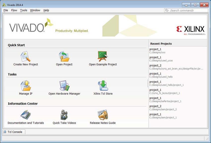
Boot Architecture

          Device Configuration Interface
          The Device Configuration Interface contains the direct memory access controller DMAC used in
          boot. The DMAC transfers partitions from one memory, usually NVM, to another memory,
          usually DDR, at a high transfer rate. The DMAC interfaces to the PS using the AXI bus, and to the
          PL using the PCAP interface.

          Secure Storage
          Secure storage is on-chip memory which is inaccessible to an adversary. The memory resides
          within the security perimeter of Zynq devices. At build time, the designer controls input/outputs
          (I/Os) and internal switches to restrict access to Zynq device internal components. The OCM, L1
          and L2 cache, AXI block RAM, PL configuration memory, BBRAM, and eFUSE array are secure
          storage in Zynq devices.

          Nonvolatile Memory
          The types of NVM used to boot Zynq devices are Secure Digital (SD), Quad Serial Peripheral
          Interface (QSPI), NAND, and NOR. The ZC702 and ZC706 Evaluation Boards support SD and
          QSPI, but not NAND and NOR NVM.

          BootROM
          The BootROM is 128K mask programmed boot Read Only Memory (BootROM) which contains
          the BootROM code. The BootROM is not visible to the user or writable. The BootROM code
          reads the Boot Mode Register, and initializes essential clocks and NVM at startup or power on
          reset. For all boot modes except JTAG, the BootROM code uses the memory controller to copy
          the FSBL partition from the specified NVM to the OCM.

          On-chip Memory
          The OCM is 256K random access memory (RAM). The initial function of the OCM is to store the
          first stage boot loader (FSBL) when the Zynq device is booted. The maximum allowable size of
          the FSBL is 192K. Since the OCM has no address or data lines at Zynq device pins, OCM is secure
          storage. The OCM can be used as secure storage for sensitive software after boot. OCM is very
          fast memory. After boot, the full 256K OCM is available.

          AXI Block RAM
          The AXI block RAM is PL RAM. It is not used in boot. It provides secure storage for sensitive
          software or data. AXI block RAM is used by both the Arm and MicroBlaze™ CPUs.

          eFUSE Array
          The PL eFUSE array is on-chip one-time programmable (OTP) NVM. The eFUSE array stores the
          256-bit AES key. It is also used to control security functions, including enabling/disabling the
          JTAG port. The PS eFUSEs store the RSA_Enable bit and the hash of the Primary Public Key (PPK)
          used in RSA authentication.

XAPP1175 (v2.2) January 14, 2021                                                 Send Feedback
                                                                                                          5
                                             www.xilinx.com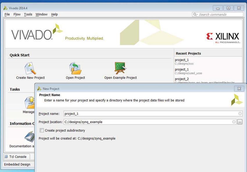
Boot Architecture

          Battery Backed Up RAM
          The battery-backed RAM (BBRAM) is an on-chip alternative to eFUSE for nonvolatile AES key
          storage. BBRAM is reprogrammable and zeroizable NVM. BBRAM is NVM when an off-chip
          battery is connected to the Zynq device. The ZC702 board provides the battery, the Zed board
          does not. The BBRAM can be used to store the AES key when a battery is not attached, but it is
          volatile.

          AES/HMAC
          The Advanced Encryption Standard (AES) is used for symmetric (secret) key
          encryption/decryption. The Hashed Message Authentication Code (HMAC) provides private key
          authentication using the SHA-256 hash function.

          AES cryptography is used by Zynq devices to provide confidentiality. The Zynq device contains
          a hardened AES decryption engine which is coupled to the HMAC engine. The AES
          decryption/HMAC authentication cannot be decoupled. The software development kit (SDK)
          Bootgen tool encrypts the software in the software development process, at the customer’s
          manufacturing end. Decryption is done in the fielded embedded device. The AES decryption
          uses a secret (or red) key programmed into either eFUSE or BBRAM.

          JTAG Debug Access
          The JTAG test access port (TAP) is a boundary scan chain used by the PL. The debug access port
          (DAP) is a boundary scan chain used by the PS. The two chains can be cascaded or used
          independently. Overall, they can load PS and PL code, program the keys in eFUSE and BBRAM,
          and be used for Arm debugging.

          Software Components Used in Boot
          The Xilinx Vivado Design Suite is used for system development and to implement VHDL/Verilog
          code. SDK is used to compile C code, generate a boot image, load the boot image, and debug
          the software and hardware.

          SDK is used to create software projects, and download and debug the projects. SDK runs on a
          workstation under Windows or Linux. The software programs which run on Zynq devices and
          are used in boot are the BootROM code, FSBL, ps7_init, U-Boot, and the DEVCFG code.

          Boot Header
          The Boot Header defines characteristics of the FSBL partition. The image ID and Header
          Checksum fields in the Boot Header allow the BootROM code to run integrity checks. The
          Encryption Status field specifies whether the FSBL is non-secure or secure, and if secure,
          whether the key source is eFUSE or BBRAM. The Boot Header format is provided in the
          Zynq-7000 SoC Technical Reference Manual (UG585) [Ref 1]. For additional information see
          Zynq-7000 SoC Software Developers Guide (UG821) [Ref 2].

XAPP1175 (v2.2) January 14, 2021                                               Send Feedback
                                                                                                       6
                                            www.xilinx.com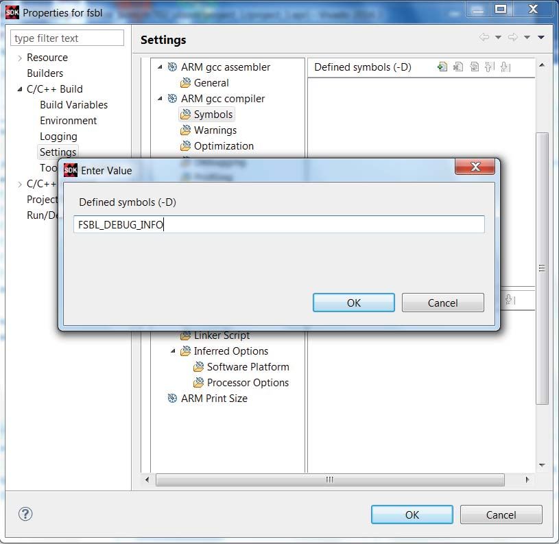
Boot Architecture

          Bitgen/Write Bitstream
          Bitgen (ISE) or write_bitstream (Vivado) generates an unencrypted bit file for the bitstream
          partition. Bitgen or write_bitstream are not used for encryption in Zynq devices. See the following
          Bootgen section for details.

          Bootgen
          Bootgen is a SDK tool which generates the image for booting. Bootgen generates the image
          which is loaded into NVM. Bootgen accepts a user generated Bootgen Image Format (BIF) file
          that lists the partitions which are to be included in the image. Bootgen outputs a single image
          file in MCS or BIN format. Bootgen optionally encrypts and signs partitions, using AES and RSA
          algorithms respectively.

          Secure Key Driver
          The Secure Key Driver software programs the PS and PL eFUSE array. The Secure Key Driver runs
          on Zynq devices and requires an external physical connection between the Zynq external JTAG
          pins and the Zynq external MIO pins. See Changing the Cryptographic Key in Zynq-7000 AP SoC
          (XAPP1223) for details [Ref 3]. If RSA authentication is used, the Secure Key Driver must be used
          to program the PS eFUSE array. If AES Encryption is used, th eFUSE Driver is an alternative to
          using iMPACT to program the AES key. The steps to use the Secure Key Driver are given in the
          Secure Key Driver section.

          First Stage Boot Loader (FSBL)
          The FSBL is the partition loaded into OCM by the BootROM code. The FSBL loads partitions
          (software programs, the bitstream) in the image, which is stored in NVM, to the partitions
          destination. The destination of software partitions is usually DDR, OCM, or AXI BBRAM. The
          destination of the bitstream is the PL configuration memory. Using the AES/HMAC engine and
          the RSA libraries, the FSBL controls the decryption and authentication process. Although the
          functionality of the FSBL meets most user load requirements, the source code is editable if there
          are custom requirements. For example, the RSA_SUPPORT symbol needs to be defined in the
          fsbl.h header file to enable RSA authentication within the FSBL.

          iMPACT/Hardware Manager
          iMPACT (ISE) or Hardware Manager (Vivado) are used to program FPGAs, including the PL,
          principally in development. The iMPACT or Hardware Manager tools program the PL eFUSE
          array or BBRAM, including control parameters and the 256-bit AES key.

          Xilinx Microprocessor Debugger (XMD) / Xilinx Software Command-Line Tool
          (XSCT)
          XMD/XSCT are SDK tools commonly used to load PL and PS partitions in development. In
          addition to loading partitions. XMD/XSCT are used to quickly test device functionality.
          XMD/XSCT uses the JTAG port, so it cannot be used in secure boot.

XAPP1175 (v2.2) January 14, 2021                                                   Send Feedback
                                                                                                            7
                                              www.xilinx.com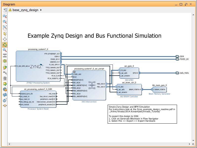
Boot Architecture

          Note: XMD has been deprecated and is only available in tools older than 2018.1.

          U-Boot
          U-Boot is open source software that runs on Zynq devices. It is commonly used to load Linux.
          Other U-Boot functions include reading DDR memory, and erasing, reading, writing NVM.
          U-Boot is loaded by the FSBL, XMD, or XSCT. It is used in both secure and non-secure boot, but
          is not required for either.

          BootROM Code
          BootROM code is metal-masked and immutable ROM code which runs at power-up and in some
          cases in a multiboot. The BootROM code determines the boot mode, initializes the memory
          controllers used in boot, and if in a boot mode other than JTAG, loads FSBL into the OCM.

          Chain of Trust
          Booting a device securely starts with the BootROM code loading the FSBL and continues serially
          with the FSBL loading the bitstream and software. With a secure boot foundation established by
          the boot ROM code, the chain of trust is created by the successive authentication of all software
          loaded into the device. This prevents an adversary from tampering with software or the
          bitstream file.

          Device Configuration (devcfg)
          The devcfg is the Xilinx device configuration driver which uses the direct memory access
          controller (DMAC) to load the bitstream and software. Typical uses of the devcfg software are to
          load the bitstream from non-volatile memory (NVM) to random access or configuration
          memory.

          Image
          An image is a file which contains the PL bitstream and PS software which define Zynq
          functionality. Typically, an image is loaded into NVM first. At power up, the image is copied
          from NVM into RAM and/or configuration memory as part of the boot process. An image
          consists of one or more partitions (typically more than one). In addition to the bitstream and
          software partitions, the image contains header (boot, partition) information used to define the
          characteristics of the partitions and image.

          Partition
          Partitions are the individual PL bitstream and PS software (ELF, BIN) that comprise an image.
          Example partitions are system.bit, fsbl.elf, hello_world.elf, u-boot.elf,
          uImage.bin, devicetree.dtb, and uramdisk.image.gz.

XAPP1175 (v2.2) January 14, 2021                                                    Send Feedback
                                                                                                          8
                                              www.xilinx.com
Boot Process

          Boot Image Format (BIF)
          The BIF is the input file into Bootgen that lists the partitions (bitstream, software) which
          Bootgen is to include in the image. The BIF also includes attributes for the partitions. Partition
          attributes allow the user to specify if the partition is to be encrypted and/or authenticated.

          ps7_init
          The ps7_init command is an alternative to using an FSBL in a non-secure boot. The ps7_init
          command provides a simple method to initialize boot components during development when
          XSCT is used.

          RSA
          RSA is a public key algorithm used to authenticate software, including ELF, BIN, and BIT
          partitions. Authentication verifies that software has not been modified. In Zynq devices, each
          software partition can be individually authenticated. RSA uses a public/private key pair. The
          private key is used by Bootgen in signing the partition at the customer’s manufacturing facility.
          The public key is used in verifying the partition in the fielded Zynq device.

          Software Development Kit
          SDK is Eclipse-based software which is downloadable from the Xilinx website. In addition to
          software development, SDK supports creating images, downloading software and the bitstream
          into the Zynq device, writing the image into QSPI, and debugging software programs.

Boot Process
          This section provides an overview of boot modes, boot steps, boot flows, and maintaining
          security after boot. Following this, the software used in boot, including the BootROM code,
          FSBL, and U-Boot, is discussed.

          Boot Modes
          The boot modes are PS Master Non-secure, PS Master Secure, and JTAG. The master modes use
          QSPI, SD, NAND, or NOR NVM.

XAPP1175 (v2.2) January 14, 2021                                                  Send Feedback
                                                                                                           9
                                             www.xilinx.com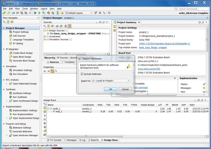
Boot Process

          Secure Boot Steps
          Figure 3 shows the steps to develop a secure embedded system.
          X-Ref Target - Figure 3

                                                      Generate AES, RSA Keys

                                                Use the Secure Key Driver to Program
                                                      RSA Enable, PPK Hash
                                                        Program AES Key

                                                  Use Bootgen to Create Image
                                                     in MCS or BIN Format

                                                   Program QSPI with MCS File
                                                              or
                                                     Program SD with BIN file
                                                                       XAPP1175_3_070513

                                    Figure 3:    Steps in Developing a Secure System

          Boot Flows
          To boot the Zynq device, software (FSBL, U-Boot) is developed on a workstation using SDK, and
          the image is created by Bootgen. Running on Zynq devices, the FSBL loads the software used by
          Zynq devices.

          Two distinct load operations are required: loading an image into NVM, and copying partition(s)
          from NVM to DDR (or OCM). The SDK Flash Programmer, zynq_flash, or U-Boot load an image
          into QSPI.

          If SD is used, a BIN image is written to the SD card. This uses a SD card reader/writer which is
          connected to the workstation with a USB cable. The SD card goes into the ZC702 Evaluation
          Board SDIO slot (J64).Copying the image from the SD card or QSPI is done by FSBL or U-Boot.
          In loading NVM, all partitions are typically loaded into flash or SD. Booting Zynq is commonly a
          two step process, with the FSBL loading the bitstream file and U-Boot partitions, and U-Boot
          loading the remaining partitions. The remaining partitions are usually Linux partitions,
          including Linux applications.

          While it is common for U-Boot to load Linux and Linux applications, in most of the use cases in
          this application note, the FSBL loads U-Boot, Linux, and the Linux applications. U-Boot is still
          loaded because it is used for functions other than loading Linux. Using the FSBL to load Linux
          partitions allows the user to specify whether each partition is encrypted or authenticated.

          If the boot mode pins specify JTAG, the BootROM code enables the JTAG port. XSCT is used to
          load and run software. In the JTAG boot mode, the FSBL displays a message that JTAG boot
          mode is used. The FSBL does not load partitions when JTAG mode is used. In a non-secure JTAG
          boot, either the FSBL or ps7_init initializes boot components.

XAPP1175 (v2.2) January 14, 2021                                                           Send Feedback
                                                                                                           10
                                                www.xilinx.com
Boot Process
BootROM code
The BootROM code does the initial setup at boot. If the boot is a Master Secure or Master
Non-Secure boot, the BootROM code initializes the NVM controller specified by the boot mode
register, parses the boot header, and copies the FSBL to OCM.
Figure 4 shows the BootROM code flow. The BootROM code reads the boot mode register to
determine if a master or slave boot mode is used, and if master, the type of NVM used. The
BootROM code reads the Boot Header to determine whether the boot is non-secure or secure,
and if secure, whether the key source is BBRAM or eFUSE. If there is a key mismatch between the
key source specified in the PL eFUSE array and the key source specified in the boot header, the
BootROM code transitions the Zynq device to a secure lockdown state. If the BootROM code
determines that the device is in an illegal boot mode based on its state, the BootROM code
transitions the Zynq device to a secure lockdown state. An example of an invalid state is a Boot
Header in which the Encryption Status field specifies encryption using BBRAM and the PL eFUSE
array specifies an eFUSE only key source. In a secure boot, the BootROM code executes
proprietary tests to ensure security before it authenticates the FSBL.
In the eXecute In Place (XIP) mode, the CPU runs code directly from NVM rather than DDR. The
XIP mode cannot be used in secure boot.
XAPP1175 (v2.2) January 14, 2021 Send Feedback
11
www.xilinx.comBoot Process
X-Ref Target - Figure 4
Power Up ||
POR
S - Secure
NS - Non-secure
Clear PS, PL
Key Mismatch ||
Boot Mode Register Illegal Boot Mode ||
Boot Header Error ||
Boot Flow Error
Initial Secure
Boot Header Boot Lockdown
Efuse Array
Initialize Clocks, Mem Ctlrs
Master (Unencrypted) Master (Encrypted)
BH Length = 0 Boot Flow
Security Disable & Error || XIP
CPU Idle
Master Master
NS Initial XIP JTAG S Initial
Boot Boot
Move FSBL: NVM->OCM Move FSBL:NVM->OCM Unlock/Lock
thru AES/HMAC Engine Subsystems &&
pcfg_aes_en=1
NS First
Stage Boot
Multiboot Error
S First
Initialization, Move Images
Stage Boot
Multiboot Error
Initialization, Move Images
Authenticate, Enable Decryption if Specified
XAPP1175_05_061513
Figure 4: BootRom Code Flow Diagram
First Stage Boot Loader
The first stage boot loader (FSBL) is loaded into OCM by the BootROM code. The FSBL is closely
aligned with Bootgen in that it reads the partitions in the image created by Bootgen. The
principle function of the FSBL is to copy partitions from NVM to DDR and PL configuration
memory. If the partition is encrypted, the partition is routed to the AES/HMAC engine for
decryption before it is loaded in DDR or other destination address. If the system.bit is in the
image, the FSBL transfers the system.bit into the PL configuration memory. It then transfers
the second stage boot loader (SSBL) or application partition(s) to their destination address,
typically DDR. The FSBL can load multiple ELF files.
A second method of loading partitions is for the FSBL to load u-boot.elf, and U-Boot loads
software partitions.
Prior to loading partitions, the FSBL completes the initialization of the device started by the
BootROM code. The multiplexed input/output (MIO), clocks, and DDR controller are initialized.
XAPP1175 (v2.2) January 14, 2021 Send Feedback
12
www.xilinx.comBoot Process
The FSBL supports most user's software load requirements. In some cases, users need to edit
the FSBL source code to meet additional load or functional requirements. As an example, the
User Defined Field in the Authentication Certificate can be used for a function such as defining
the software version being loaded. To support this, the FSBL code would require edits which
check that the correct software version is loaded. The FSBL source code is in the src directory
of the zynq_fsbl_0 software project.
Note: The FSBL code most likely to be edited is in main.c and image_mover.c
FSBL hooks provide a framework to plug in user-defined functions. An example use of the FSBL
hooks is to initialize PL cores after a bitstream is downloaded. The FSBL hook functions in
fsbl_hook.c are:
• FsblHookBeforeBitstreamDload: Provides a region for FSBL edits before bitstream
download
• FsblHookAfterBitstreamDload: Provides a region for FSBL edits after bitstream download
• FsblHookBeforeHandoff: Provides a region for FSBL edits before the FSBL hands off to the
SSBL or an application.
The TRD system in zc702_linux_trd provides an example of FSBL edits in initializing an I2C. In
XAPP1078 Simple AMP Running Linux and Bare-Metal System on Both Zynq SoC Processors, the
FSBL searches for additional partitions to load.
XAPP1175 (v2.2) January 14, 2021 Send Feedback
13
www.xilinx.comBoot Process
Figure 5 shows a flow chart of the FSBL.
X-Ref Target - Figure 5
Initialization
Read Partition Header
Authentication Certificate? N
Y
RSA Verify Partition
N
Partition Encrypted?
Y
Route Partition to
AES-HMAC Engine
Route Partition to
Destination
N
Last Partition
Handoff Executable
Partition
XAPP1175_06_080113
Figure 5: FSBL Flow
The FSBL parses the boot image to determine if the image is to be RSA authenticated and/or
AES decrypted. If the partition is AES encrypted, the FSBL routes the partition to the AES/HMAC
engine, and then to its final destination. If the partition is RSA authenticated, the FSBL reads the
authentication certificate (AC) which contains the public key and the signature.
XAPP1175 (v2.2) January 14, 2021 Send Feedback
14
www.xilinx.comAES Encryption and RSA Authentication
The FSBL uses the sha256 and rsa2048_ext library functions to authenticate the partition. The
sha256 and rsa2048_ext compiled functions reside in $XILINX_EDK/lib. The FSBL parses the
image in NVM, executing these steps:
• Verify the Secondary Public Key (SPK) using RSA
• Verify the partition using RSA
The RSA functions called in the FSBL code are conditionally executed based on the existence of
partition authentication certificates in the image.
U-Boot
U-Boot is an open source boot loader commonly used in embedded systems. U-Boot performs
similar functions to the FSBL. U-Boot has additional functions, such as reading and writing NVM
and DDR. The zc702_uboot reference system provides a system with U-Boot. U-Boot typically
runs in DDR, not OCM. The wiki.xilinx.com site provides information on configuring and
building U-Boot. In addition to loading Linux from NVM to DDR, U-Boot is used to read DDR,
and to erase, write, and read NVM. The U-Boot erase, read, and write operations on QSPI are an
alternative to the SDK Flash Writer, which runs on a workstation. U-Boot runs on Zynq devices.
U-Boot can run interactively, providing a zynq-uboot prompt, or it can run automatically at
power up. The zynq_common.h file in the include/configs directory contains options
which set U-Boot functionality. After configuration edits, U-Boot must be re-compiled as
described in wiki.xilinx.com. For development, configure U-Boot with a 5 second delay. For
production, particularly for secure boot, re-configure with a 0 delay, and rebuild U-Boot.
AES Encryption and RSA Authentication
Bootgen and FSBL software support AES encryption, HMAC authentication, and RSA
authentication. RSA is effective for authentication. AES is more efficient than public key
cryptography in encryption. Private keys are used in AES encryption and HMAC authentication,
and private/public key pairs are used in RSA authentication. For RSA authentication, Bootgen
signs partitions and the BootROM code and the FSBL verifies partitions.
The private/public key pair used in RSA authentication have significant security advantages
over cryptography which only uses private keys. In RSA, the private key is used at the
manufacturing facility which usually has physical security. The public key is loaded into the
embedded device. If an adversary steals the embedded device and extracts the public key, the
damage is limited. The RSA key pairs can be changed as often as needed. Changing the key
reduces the risk that the key is compromised, and reduces the vulnerability of the IP the key is
protecting.
Zynq devices provide a silicon based AES/HMAC engine which decrypts/authenticates at
100 MB/s. The AES/HMAC engine does not encrypt. AES-256 is used for encryption/decryption
and HMAC is used for private key authentication. AES encryption is done by Bootgen. The AES
and HMAC functions in the AES/HMAC engine cannot be used independently to
XAPP1175 (v2.2) January 14, 2021 Send Feedback
15
www.xilinx.comAES Encryption and RSA Authentication
decrypt/authenticate partitions. AES is a symmetric cryptographic algorithm which uses a
private 256 bit key. The HMAC key is a 256 bit private key.
The RSA asymmetric cryptographic algorithm in Zynq devices uses a 2,048 bit modular.
Modular is the generally accepted description of the key length. The BootROM code
authenticates the FSBL partition, and the FSBL authenticates the partitions it loads. The
BootROM code and FSBL use the identical RSA algorithm.
Since Bootgen signs partition(s) and the BootROM code and the FSBL verify the partitions,
Bootgen, BootROM code, and FSBL software must agree on the image format. For each partition
authenticated, an authentication certificate (AC) field in the image is used for RSA
authentication.
Figure 6 shows the interaction between Bootgen and the FSBL. Bootgen runs on a workstation,
and the FSBL runs on Zynq devices. For each partition, Bootgen executes the cryptographic
functions in the order shown. Similarly, in loading each partition, the FSBL executes the
cryptographic functions in the order shown.
X-Ref Target - Figure 6
Customer’s Workstation ZC702
Bootgen FSBL
HMAC Sign RSA Verify
AES Encrypt AES Decrypt
RSA Sign HMAC Verify
XAPP1175_25_050119
Figure 6: FSBL — Bootgen Interaction
In Bootgen, the HMAC is generated first, followed by AES encryption, followed by RSA signing.
In Zynq devices, these steps are reversed: the partition is RSA authenticated, AES decrypted,
and then HMAC authenticated. Note that the data, HMAC signature, and HMAC key are all
encrypted (wrapped) by the AES encryption process.
In RSA authentication, the partition is not signed. Instead, a hash of the partition is generated,
using a SHA256 function. The SHA256 hash is a one way function which produces the same size
output, independent of whether the partition size is 1,000 bytes or 1 MB. The hash is signed
using the private key. For each partition which is RSA authenticated, Bootgen writes an
Authentication Certificate (AC) which contains the public keys and the signatures for the
partition.
XAPP1175 (v2.2) January 14, 2021 Send Feedback
16
www.xilinx.comSecurity in Embedded Devices
Security in Embedded Devices
Security should be considered at the beginning of embedded device development, starting
with identifying potential threats. Potential threats to an embedded device are provided in the
following list:
• Theft of the Embedded Device
• Privacy of the data in the Embedded Device or System
• Cloning of the Embedded Device
• Denial of Service
• Insertion of malware to change the behavior of the Embedded Device
• Insider Providing Key to Adversary
Figure 7 is a boot flow in which authentication is used to load partitions in a chain of trust. The
BootROM code loads the FSBL. The FSBL and U-Boot boot loaders load the hardware and
software partitions. The principle objectives in a secure boot are to prevent an adversary from
loading a modified partition, and to keep proprietary partitions confidential.
X-Ref Target - Figure 7
BootROM SSBL OS
FSBL Bitstream Apps
Code U-Boot Linux
XAPP1175_02_050119
Figure 7: Chain of Trust in Secure Boot
In Bootgen, users define which partitions are encrypted, and which partitions are authenticated
using a RSA private/public key pair. Authenticating all partitions in a chain of trust ensures that
only partitions which have not been tampered with are loaded.
An important part of embedded device security is key security. An advantage of RSA is that the
private key is not loaded into the device. A second advantage is that different RSA keys can be
specified for each partition, and the RSA key can be changed when partitions are updated.
Changing the key limits the time an adversary has to attack the key, and limits the information
that is vulnerable.
To facilitate key security, Bootgen provides the ability to handle RSA keys securely, limiting
access to an Infosec staff. Since only the Infosec staff has access to keys used in the final
embedded product, this reduces the threat of an insider attack.
Zynq devices also provide security by integrating a large amount of software and hardware IP
within its security perimeter. A combination of build options and software allows the protection
of IP within the security perimeter. Additionally, Zynq devices have a relatively large amount of
secure storage available for sensitive program and data storage. Since this storage is not large
enough to hold the Linux OS, system partitioning of sensitive and non-sensitive functions is
required. Linker script and BIF attributes allow open source code to run from DDR and sensitive
XAPP1175 (v2.2) January 14, 2021 Send Feedback
17
www.xilinx.comSecure System Development
applications to run from on-chip secure storage. The Secure Key Driver section provides a linker
script which locates code from On-Chip Memory (OCM).
Embedded systems are commonly attacked after a secure boot (i.e., during operation). The
loaded software, such as the operating system, should not allow an adversary access to Zynq
hardware or software resources.
In a secure boot, all partitions are loaded in a chain of trust. After the transition from the boot
stage to an operational stage (i.e. when Linux applications have been loaded), the OS must
maintain the system as secure. In a non-secure boot, U-Boot and Linux applications can load
the bitstream. After Linux is loaded, an application can use the devcfg driver to load a bitstream.
Restated, the OS should not allow access to the devcfg driver to non-trusted users/applications.
The most direct method to do this is to keep the module out of the kernel build. Linux has
supervisor/user modes. If the devcfg driver is included in the Linux build, the supervisor needs
to restrict access, requiring passwords for users and limiting the devcfg file permissions to only
the supervisor.
The PS-PL architecture provides the user with the ability to provide redundancy in recovering
from operational failure in either the PS or PL. The PS can monitor the PL for a tamper event
triggered by single event upset (SEU) activity. The PL can monitor the PS using a security
monitor.
In addition to secure boot, embedded device security requirements may include anti-tamper
and information assurance. Xilinx sells a high-end, fully tested security monitor IP which
executes from the PL. Alternatively, a user can develop a security monitor which does not
consume PL logic resources. Using the Zynq-7000 Processing System to Xilinx Analog to Digital
Converter Dedicated Interface to Implement System Monitoring and External Channel
Measurements (XAPP1172) [Ref 5] is recommended as a good start in developing a lite security
monitor.
Anti-tamper (AT) is discussed in Developing Tamper Resistant Designs with Xilinx Virtex Series 6
and 7 FPGAs [Ref 14]. Information assurance (IA) is discussed in Solving Today’s Design Security
Concerns (WP365) [Ref 6].
Secure System Development
The steps in Creating a Project Using the Vivado Design Suite are used to initially test a basic
secure system. Zynq devices have many security options not discussed in this section. Figure 8
shows a typical secure development process which allows users to incrementally learn to use
Zynq device security features. This approach is used because once the eFUSE key and eFUSE
only control bit are programmed, there is no returning to using the BBRAM key if the eFUSE key
is lost. Also, once the RSA Enable eFUSE is programmed, a board cannot be used without at
least FSBL authentication in the master mode.
The process described in this section is not required, and is presented because Zynq devices
provide many security options with RSA and AES/HMAC. After starting with a non-secure
design, a subsequent step is a secure design using a BBRAM AES key. The BBRAM AES key is
XAPP1175 (v2.2) January 14, 2021 Send Feedback
18
www.xilinx.comSecure System Development
reprogrammable. The next step is to enable RSA authentication. The RSA Enable eFUSE control
bit and the hash of the PPK are programmed into the PS eFUSE area using the Secure Key Driver.
BBRAM can still be used as the source of the key for AES decryption.
X-Ref Target - Figure 8
Non-Secure Design
Secure Boot - BBRAM
Secure Boot - eFUSE
Secure Boot - eFUSE only
Bootgen
Debug Mode -> Release Mode
XAPP1175_24_051613
Figure 8: Learning to Use Zynq-7000 SoC Security Options
The next step is to use the eFUSE key for AES decryption. At this stage, a non-secure boot, RSA
authentication, secure boot with BBRAM AES key, and a secure boot with an eFUSE key are
possible. The board must be powered down to change the AES key source. If the RSA Enable bit
is programmed, the FSBL must be authenticated. An RSA enabled “non-secure” boot differs
from the un-authenticated non-secure boot.
Key Swapping eFUSE and BBRAM keys
Keys can be programmed in either eFUSE or BBRAM NVM. The advantages of BBRAM is that it
can be reprogrammed, and it can be erased if there is a tamper event. The eFUSE array control
bits eFUSE Secure Boot and BBRAM Key Disable prohibit swapping between the eFUSE and
BBRAM key. If these bits are not programmed, either key source can be used after a power
down. If BBRAM Key Disable is programmed but eFUSE Secure Boot is not programmed, a
non-secure boot or a secure boot using the eFUSE key can be done. To use only the eFUSE as
the AES key source, the eFUSE Secure Boot Only bit is programmed in the PL eFUSE control
XAPP1175 (v2.2) January 14, 2021 Send Feedback
19
www.xilinx.comBooting the TRD Securely
array. The PL eFUSEs can be programmed either with iMPACT, HW Manager, or the Secure Key
Driver. The Secure Key Driver section shows how to program this functionality.
The last option in the figure, Bootgen Release mode, is used by the Infosec staff for the
production release of the secure embedded device. In this stage, Bootgen Release mode can be
used to increase the security of the RSA private key. This is discussed in the Advanced Key
Management Options section.
Booting the TRD Securely
The source files for booting the ZC702 Base System TRD quickly are provided in the
zc702_linux_trd reference system. This section provides an example, the Target Reference
Design, which shows that the creation of a secure boot image is straightforward. This section
uses pre-existing keys in the reference design systems. There is a section on Generating Keys
later in this document.
Note: Using the following step, the PS eFUSEs are blown. After this, in all subsequent tests using the
ZC702, at least the FSBL partition must be authenticated.
Use the following steps to boot the TRD securely.
1. Setup the ZC702 board. See the Setup the ZC702 Evaluation Board section. Set the Boot
mode switches to JTAG boot mode.
2. Invoke the Tera Term communication terminal and set Baud Rate = 115200, Data = 8 Bits,
Parity = None, Stop Bit = 1, Flow Control = None.
3. Change to the xapp1175/zc702_secure_key_driver/ready_for_download
directory. This directory contains the ps_secure_key_read.elf and
ps_secure_key_write.elf files. If the eFUSEs are programmed, run the
ps_secure_key_read.elf in step 4. If the eFUSEs need to be programmed, and it is
acceptable to use the Xilinx provided keys for the evaluation board, run the
ps_secure_key_write.elf in step 4.
4. Run xsct at a command prompt or from SDK, and run the following:
connect arm hw
source ps7_init.tcl
ps7_init
then either:
dow ps_secure_key_write.elf (if programming the eFUSEs)
or
dow ps_secure_key_read.elf (if reading the eFUSEs)
con
XAPP1175 (v2.2) January 14, 2021 Send Feedback
20
www.xilinx.comBuilding and Booting a Secure System
5. Optionally, verify that the hash of the PPK displayed in the communication terminal matches
the values in
xapp1175/zc702_efuse_driver/ready_for_download/hash_ppk.txt.
6. Change to the xapp1175/zc702_linux_trd directory.
7. Run bootgen -image zc702_linux_trd.bif -o zc702_linux_trd.mcs
-encrypt bbram.
8. Invoke SDK. Select the workspace as xapp1175/zc702_linux_trd/SDK.
9. In SDK, enter Xilinx Tools > Program Flash.
10. Specify the image by browsing to
xapp1175/zc702_linux_trd/zc702_linux_trd.mcs.
11. Set the offset to 0x0. Set the flash type to QSPI Single. Click Program.
12. On the ZC702 Evaluation Board, change the boot mode switch to QSPI boot mode by
moving the J25 jumper to 1 (or 4 if the evaluation board uses the single switch).
13. Power cycle. Verify that Zynq boots to the PetaLinux prompt. To login, use root for the user
name and root for the password.
14. To compare non-secure and secure boot time, repeat step 7 to step 13. When re-running
step 7 for a non-secure BIF, eliminate the -encrypt bbram argument, but program QSPI
instead with zc702_linux_trd_ns.mcs.
Building and Booting a Secure System
This section provides the steps to develop a Zynq system using the GUIs provided by the Xilinx
Vivado Design Suite and SDK. The steps for AES key generation and creating non-secure and
secure images are provided. The steps for setting up the ZC702 evaluation board are given. The
zc702_uboot system is booted using JTAG mode. This is followed by non-secure and secure
boots using ZC702 SD and QSPI memory.
The required tasks for a secure boot are:
• Create the Zynq hardware and software using Xilinx software
• Use Bootgen Advanced Tab to generate a secure image
• Use Bootgen to generate the AES key
• Use iMPACT, HW Manager, or the Secure Key Driver to program the AES key to either
BBRAM or eFUSE
• Load the SD Card or Program QSPI flash on ZC702 Evaluation Board
This section provides an introduction to developing a system and using the Bootgen GUI.
Bootgen supports mixed encrypted/unencrypted partitions, user selectable security on
partitions, and RSA authentication when run at the command line.
XAPP1175 (v2.2) January 14, 2021 Send Feedback
21
www.xilinx.comBuilding and Booting a Secure System
Note: The steps in this section only work on a board on which the RSA Enable has not been
programmed. The design files for this section are meant to be created by the reader. The design files in
the zc702_uboot system are for a board in which RSA_Enable has been programmed.
Details on advanced security functionality are provided in later sections. The later sections do
not require the files produced in this section.
Creating a Project Using the Vivado Design Suite
In this section, the Vivado Design Suite is used to create the zynq_example project. The system
includes AXI GPIO and AXI block RAM in the PL.
Note: Depending on the version of the Vivado tools you are using, the figures and filenames might
somewhat differ.
1. Under Search Programs, select Xilinx Design Tools > Vivado > Vivado
. Figure 9 shows the Vivado Design Suite GUI.
X-Ref Target - Figure 9
X1175_07_040115
Figure 9: Vivado Design Suite GUI
XAPP1175 (v2.2) January 14, 2021 Send Feedback
22
www.xilinx.comBuilding and Booting a Secure System
2. Click Open Example Project (see Figure 10). Click Embedded Design. Click Next. Click
Create a Template Based Vivado Project. Click Next. Provide the name and location of the
project as shown in the figure. Select Base Zynq Design. Click Next. Select Zynq-7 ZC702
Evaluation Board. Click Next. Click Finish.
X-Ref Target - Figure 10
X1175_08_040115
Figure 10: Selecting the ZC702 Evaluation Platform
XAPP1175 (v2.2) January 14, 2021 Send Feedback
23
www.xilinx.comBuilding and Booting a Secure System
3. Under IP Integrator (or Flow Navigator depending on Vivado version), select Open Block
Design. Click Validate Design. Under Sources, right-click base_zynq_design, and select
Generate Output Products. Under IP Integrator (or Flow Navigator), click Generate
Bitstream (see Figure 11).
Note: It might take several minutes to complete all the steps up to and including bitstream
generation.
X-Ref Target - Figure 11
X1175_09_040115
Figure 11: Zynq Example Board Design Schematic
XAPP1175 (v2.2) January 14, 2021 Send Feedback
24
www.xilinx.comBuilding and Booting a Secure System
4. Select File > Export - Export Hardware (see Figure 12). Check Include Bitstream. Select
File > Launch SDK - Local to Project >OK (see Figure 13).
X-Ref Target - Figure 12
X1175_10_040115
Figure 12: Exporting Hardware Design to SDK (1 of 2)
XAPP1175 (v2.2) January 14, 2021 Send Feedback
25
www.xilinx.comBuilding and Booting a Secure System
X-Ref Target - Figure 13
X1175_60_010415
Figure 13: Exporting Hardware Design to SDK (2 of 2)
XAPP1175 (v2.2) January 14, 2021 Send Feedback
26
www.xilinx.comBuilding and Booting a Secure System
5. Create the FSBL project. Select File > New > Application Projct. The Application Project
dialog box is displayed. Enter fsbl as the project name. Select the Create New Board
Support Package option. Click Next. The New Project Templates dialog box is displayed.
Figure 14 shows the creation of the FSBL project. Select Zynq FSBL and click Finish.
X-Ref Target - Figure 14
Figure 14: Creating the First Stage Boot Loader (FSBL) Software Application
XAPP1175 (v2.2) January 14, 2021 Send Feedback
27
www.xilinx.comBuilding and Booting a Secure System
6. Right-click on the FSBL in the Project Explorer pane and select Properties. As shown
in Figure 15, edit FSBL compilation options so that debug information is displayed in the
SDK or communication terminal window. With the Debug options used in compilation, FSBL
provides useful information on the partitions in the image. If the SD or QSPI boot modes are
used, the debug information is useful. If JTAG boot mode is used the FSBL does not copy
partitions, and therefore information is not provided.
To view details of the boot process in a FSBL debug file and enable RSA authentication
functionality, select C/C++ Build > Settings > ARM gcc compiler > Symbols and compile
using DEBUG, FSBL_DEBUG_GENERAL, FSBL_DEBUG_INFO, and RSA_SUPPORT symbols. In
the Defined Symbols pane, click the “+” icon to iteratively select the symbols. The figure
shows the entry of FSBL_DEBUG_INFO in the Enter Value dialog box. Perform this step four
times, once for each symbol.
Click Apply, then click OK. The FSBL software project is compiled. The ELF (fsbl.elf) is in
the fsbl/Debug directory.
X-Ref Target - Figure 15
X1175_13_120414
Figure 15: Using Symbol Compile Options for the FSBL Software Application
XAPP1175 (v2.2) January 14, 2021 Send Feedback
28
www.xilinx.comBuilding and Booting a Secure System
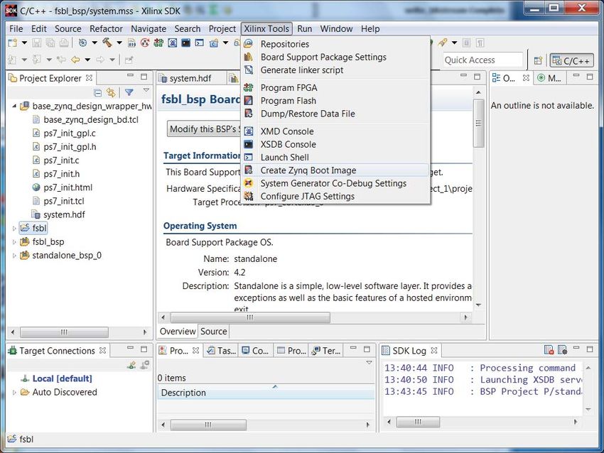
7. In SDK, select Xilinx Tools > Create Zynq Boot Image to invoke Bootgen. Figure 16 shows
the invocation of the Bootgen GUI.
X-Ref Target - Figure 16
X1175_14_040115
Figure 16: Invoking Bootgen
8. Use the Basic tab in the Create Zynq Boot Image dialog box to specify the directory and
name of the BIF file. Use the Browse button to select the fsbl.elf file from the
fsbl/Debug directory, where fsbl was specified as the project name. Add system.bit to
the list of partitions. If used, the bitstream partition must follow the FSBL partition. Add
u-boot.elf to the list of partitions. Click Create Image to generate the BIF and
non-secure BIN and MCS files (see Figure 17). The file is the input file into Bootgen that lists
the partitions to include in the image. The MCS formatted image is used in QSPI boot mode.
The BIN formatted image is used in SD boot mode. Create a directory that will contain the
resultant image file within the project area. Use the Browse button to select the new
directory as the Output folder.
XAPP1175 (v2.2) January 14, 2021 Send Feedback
29
www.xilinx.comBuilding and Booting a Secure System
X-Ref Target - Figure 17
X1175_15_120414
Figure 17: Creating a Non-secure BIF Using the Bootgen GUI
9. When encryption is selected, SDK Bootgen GUI generates a secure image in which all
partitions in the image are encrypted. The AES/HMAC engine requires a 256-bit AES key and
a 256-bit HMAC key. The AES key can be generated using the Xilinx Bootgen tool or an
external tool. To generate a development AES key using the Xilinx Bootgen software, create
a generate_aeskey.bif file with the following content:
generate_aeskey_image:
{
[aeskeyfile] bbram.nky
[bootloader, encryption=aes] fsbl.elf
}
Use the following Bootgen command to generate an AES key:
bootgen -image generate_aeskey.bif -o temp.mcs -encrypt bbram
If the specified AES key does not exist, Bootgen generates the key with the name in the
generate_aeskey.bif file (bbram.nky in this case).
10. To create a secure image, specify partitions in the Basic tab in the Create Zynq Boot Image
dialog box using the same method used for the non-secure image. Create an output
directory for the secure image. Specify this directory in the Output folder. Click on the
Advanced tab in the Create Zynq Boot Image dialog box, click Enable encryption, and
browse to the key generated in step 9. Click Create Image to create the secure boot image
(see Figure 18). Bootgen writes the image in either MCS or BIN format.
XAPP1175 (v2.2) January 14, 2021 Send Feedback
30
www.xilinx.comBuilding and Booting a Secure System
X-Ref Target - Figure 18
XAPP1175_18_120414
Figure 18: Creating an Encrypted Image
Setup the ZC702 Evaluation Board
1. Connect the power cable to the 12V J60 Connector.
2. Connect the USB cable from the workstation to the USB UART J17 Connector.
3. Connect the Platform USB Cable II to JTAG Connector J2.
Table 1 provides the function of mode select switch on the ZC702. Some ZC702 boards use
SW16, and some ZC702 boards use the J25, J22, and J20 jumpers.
Table 1: ZC702 Boot Mode Selection
MIO[5] - J25 MIO[4] - J22 MIO[3] - J20
JTAG 0 0 0
NOR 0 0 1
NAND 0 1 0
Quad-SPI 1 0 0
Secure Digital 1 1 0
After the board is setup, use the following steps to program the AES key, load the boot image,
and boot an encrypted image.
XAPP1175 (v2.2) January 14, 2021 Send Feedback
31
www.xilinx.comBuilding and Booting a Secure System
1. Open the Hardware Manager in Vivado (see Figure 19).
X-Ref Target - Figure 19
X1175_17_040115
Figure 19: Opening the Hardware Manager in Vivado
XAPP1175 (v2.2) January 14, 2021 Send Feedback
32
www.xilinx.comBuilding and Booting a Secure System
2. Use the Vivado Hardware Manager to program the BBRAM key (see Figure 20). Right-click
xc7z020 and click Program. Select Cancel when the Device Programming Properties is
displayed. The Hardware Manager can also program the eFUSE key. If eFUSE and BBRAM
keys are programmed, the Bootgen -encrypt efuse | bbram argument specifies which key is
used. Bootgen writes the key source to the Boot Header region of the image. At power up,
the BootROM code reads the Boot Header to determine which key source to use. The eFUSE
control register is also programmed with the Hardware Manager.
X-Ref Target - Figure 20
X1175_18_040115
Figure 20: Using Vivado Hardware Manager to Program the BBRAM Key
XAPP1175 (v2.2) January 14, 2021 Send Feedback
33
www.xilinx.comBuilding and Booting a Secure System
3. Invoke SDK by running xsdk & at the Linux prompt, or Xilinx Design Tools > SDK
> Xilinx SDK from the Program Start Menu. Set the workspace at
zc702_uboot/SDK. Click the Terminal tab to setup a terminal window. Figure 21 shows how
to set up the SDK communication terminal to use a 115200 baud rate. Alternatively,
minicom, Tera Term, or Hyperterminal can be used as the communication terminal.
X-Ref Target - Figure 21
X1175_20_120414
Figure 21: SDK Communication Terminal
XAPP1175 (v2.2) January 14, 2021 Send Feedback
34
www.xilinx.comBuilding and Booting a Secure System
4. From SDK, click Xilinx Tools > Program Flash. Optionally, click Verify after Flash, and
Click Program. Figure 22 shows programming the NVM QSPI flash memory.
X-Ref Target - Figure 22
x1175_21_080913
Figure 22: Programming QSPI NVM
To program QSPI at the command prompt, enter the following XSCT command (either from
within the GUI or in command line mode):
zynq_flash -f u-boot.mcs -offset 0x0
Note: This assumes the u-boot.mcs is in the current directory. Use the full path if it is in a different
directory.
XAPP1175 (v2.2) January 14, 2021 Send Feedback
35
www.xilinx.comBuilding and Booting a Secure System
5. Set the J20/22/25 switches to select the QSPI boot mode. Power cycle the board. Figure 23
shows the communication terminal output with the U-Boot prompt.
X-Ref Target - Figure 23
x1175_22_080913
Figure 23: Communication Terminal Output after Running U-Boot Application
6. To boot using the SD card, copy the .bin created by Bootgen to BOOT.bin.
Connect a SD/MMC Card Reader/Writer to a workstation using a USB cable. Copy
BOOT.BIN to the SD card. Insert the card into the SD MMC slot. Set the Boot Mode settings
to SD (011). Power cycle. Verify that the same output is displayed in the communication
terminal as when QSPI boot mode is used.
Debugging QSPI Boot Failure
If there is a functional failure after booting from QSPI mode, verify that the function works as
expected after the partitions are loaded using JTAG boot mode. Enter the following XSCT
commands:
fpga -debugdevice devicenr 2 -f system.bit
connect arm hw
rst -processor
source ps7_init.tcl
ps7_init
ps7_post_config
dow u-boot.elf
con
exit
Note: If the files are not in the current directory, use full paths to the files.
XAPP1175 (v2.2) January 14, 2021 Send Feedback
36
www.xilinx.comSecure Boot Image Considerations
Failure to boot is usually due to incorrect setup of the clocks or memory controllers. The clock
frequencies may change across releases of different versions of silicon and software.
If the JTAG boot works, the next step to debug the QSPI failure is to create a version of the FSBL
which provides debug information. This is defined in the Creating a Project Using the Vivado
Design Suite section. Create the new FSBL, and see the steps to include the debug FSBL in the
BIF. Re-run the QSPI boot, and read the FSBL debug log file to locate the boot error.
Secure Boot Image Considerations
The system architect has two considerations in creating a secure boot image. One is to specify
which partitions are encrypted and which partitions are authenticated. The other is to architect
the system so that sensitive programs and sensitive data are located in secure storage, within
the security perimeter of Zynq.
A typical software image consists of relatively large open source U-Boot and Linux partitions,
and proprietary partitions which contain software and PL IP. In most cases, only the proprietary
or sensitive partitions are encrypted. When large partitions are unencrypted, the key is exposed
less. Conventionally, open source software such as U-Boot and Linux should be authenticated to
ensure that the partitions are not modified, but not encrypted. Encryption is not a factor in
booting with a chain of trust. Encryption ensures that the partition is not readable and is
confidential. The Bootgen Image Format (BIF) file is a Bootgen input file used to specify
encryption/authentication on a partition basis.
When decryption is used, the AES/HMAC engine runs at a lower clock frequency than other
circuitry. This means that boot time can be slower than when encryption is used. The option to
leave open source partitions unencrypted may decrease boot time. In tests of QSPI on the
ZC702 board, the boot time for non-secure and secure boot are the same. The boot time can
differ for different NVM configurations and speed grades.
The first step in creating a secure system is to write the BIF file. Appendix B defines the security
requirements for sample embedded systems. The use cases provided are secure U-Boot, Linux,
and multiboot systems. Use cases are also provided for data partitions. The BIFs for the use
cases in Appendix B are given in Appendix C. The use cases are for boot at power-up, so the use
cases include the FSBL partition. Bootgen does not require the FSBL partition to be included in
the BIF. Bootgen can AES encrypt and RSA authenticate a single software or data partition. This
supports a post-boot load operation without the use of the FSBL.
The Zynq device's secure storage and security perimeter are useful in maintaining security after
handoff to Linux applications. The PL partition, which is encrypted in NVM, is decrypted and
stored in the PL configuration memory. The PS partitions can be encrypted in NVM and
decrypted by the AES/HMAC engine. The software in DDR is usually unencrypted, outside of the
Zynq security perimeter.
To protect sensitive software and data, the destination address needs to be within the Zynq
device's security perimeter, typically OCM or AXI block RAM. The Building and Booting a Secure
System section shows how to use AXI block RAM with the Arm CPUs. The eFUSE Driver section
shows how to locate code/data in OCM. Since the amount of secure storage is limited, this
XAPP1175 (v2.2) January 14, 2021 Send Feedback
37
www.xilinx.comYou can also read