Electromagnetic Loss Analysis of a Linear Motor System Designed for a Free-Piston Engine Generator - MDPI
←
→
Page content transcription
If your browser does not render page correctly, please read the page content below
electronics
Article
Electromagnetic Loss Analysis of a Linear Motor
System Designed for a Free-Piston Engine Generator
Yunqin Hu 1, * , Zhaoping Xu 2 , Lijie Yang 2 and Liang Liu 2
 1    Department of Communication Engineering, Nanjing University of Posts and Telecommunications,
      Nanjing 210003, China
 2    School of Mechanical Engineering, Nanjing University of Science and Technology, Nanjing 210094, China;
      xuzhaoping@njust.edu.cn (Z.X.); yangljname@foxmail.com (L.Y.); l.liu@njust.edu.cn (L.L.)
 *    Correspondence: huyq@njupt.edu.cn

 Received: 8 March 2020; Accepted: 4 April 2020; Published: 8 April 2020

 Abstract: A free-piston engine generator is a new type of power generating device, which has the
 advantages of high efficiency and simple structure. In this paper, a linear motor system composed of
 a moving-coil linear motor with axial magnetized magnets and a H-bridge pulse-width modulation
 (PWM) rectifier is designed for portable free-piston engine generators. Based on the finite-element
 model of the motor and physical model of the rectifier, the combined electromagnetic model is
 presented and then validated by the prototype-tested results. The electromagnetic processes of the
 linear motor system are simulated. The electromagnetic losses during the standard working cycle are
 analyzed. Under the rated reciprocating frequency of 50 Hz and the rated reciprocating stroke of
 36 mm, the mechanical-to-electrical energy conversion efficiency of 86.3% can be obtained by the
 linear motor system, which meets the requirement of portable free-piston engine generators.

 Keywords: electromagnetic analysis; electromagnetic loss; modeling and validation; moving-coil
 linear motor; PWM rectifier; free-piston engine generator

1. Introduction
      A free-piston engine generator (FPEG) is a novel power generating device, which is a combination
of a free-piston engine and a linear motor [1]. This new type of power generating device has attracted
more and more scholars’ attention due to its potential advantages of high efficiency, simple structure
and renewable alternative fuels adaptability [2]. The device can be used in portable power generation,
electric vehicles and communication base stations [3].
      The structure of a portable FPEG, studied in this paper, is shown in Figure 1. The device consists
of a mechanical body, a rectifier for power conversion, a battery for energy storage and a controller.
The mechanical body includes a free-piston engine, an air-spring for kickback, and a linear motor.
Compared with the traditional engine generator, the crankshaft is canceled, and the free-piston is
directly connected to the mover of a linear motor. The piston-mover assembly is the only moving part
of the device [4]. This structure has the advantages of compact, low mass, easy manufacture, and low
maintenance cost.

Electronics 2020, 9, 621; doi:10.3390/electronics9040621                      www.mdpi.com/journal/electronics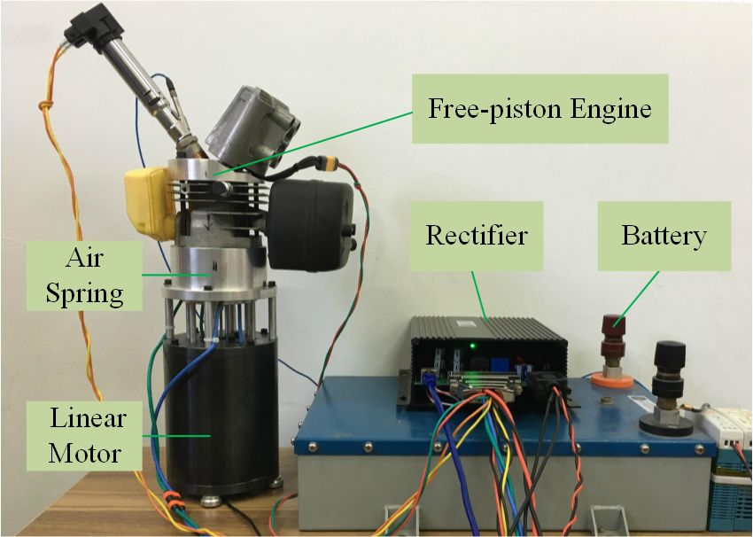
mover assembly moves down from the TTC to BTC driving by the combustion pressure.
       During the stable running, the linear motor works in generating mode all the time. The
electromotive force (EMF) in the coil of the motor is quasi-sine wave, and the generating current in
the coil is controlled as standard sine wave by the rectifier, and the electrical energy will be stored in
Electronics
the battery    in9,the
            2020,   621form of direct current. During the starting of the device, the linear motor must work
                                                                                                        2 of 11

briefly in motoring mode to start the motion of the piston-mover assembly.
Electronics 2020, 9, x FOR PEER REVIEW                                                                             2 of 11

piston-mover assembly moves up from the bottom turning center (BTC) to the top turning center
(TTC), and the mixture of air and fuel in the combustion chamber is compressed. In the expansion
stroke, the compressed mixture of air and fuel is burned and releases heat instantly, so the piston-
mover assembly moves down from the TTC to BTC driving by the combustion pressure.
     During the stable running, the linear motor works in generating mode all the time. The
electromotive force (EMF) in the coil of the motor is quasi-sine wave, and the generating current in
the coil is controlled as standard sine wave by the rectifier, and the electrical energy will be stored in
the battery in the form of direct current. During the starting of the device, the linear motor must work
briefly in motoring mode to start the motion of the piston-mover assembly.

                                    Figure 1. Free-piston engine generator sketch.
                                    Figure 1. Free-piston engine generator sketch.
     As the free-piston is not limited by the crankshaft, the reciprocating motion of the piston-mover
assembly completely depends on the instantaneous forces acted on it. The forces include combustion
pressure, electromagnetic force and spring force. The compression ratio of a FPEG is variable, thus
multiple renewable alternative fuels can be used by the device without any structural changes. These
features make the development of a FPEG competitive and valuable.
     A working cycle of the portable FPEG, studied in this paper, is shown in Figure 2. A working cycle
has two strokes: compression stroke and expansion stroke. In the compression stroke, the piston-mover
assembly moves up from the bottom turning center (BTC) to the top turning center (TTC), and
the mixture of air and fuel in the combustion chamber is compressed. In the expansion stroke,
the compressed mixture of air and fuel is burned and releases heat instantly, so the piston-mover
assembly moves down from the    Figure
                                   TTC1.to
                                         Free-piston engine
                                           BTC driving   by generator sketch. pressure.
                                                            the combustion

                            Figure 2. Working cycle of the free-piston engine generator.

     The linear motor and the rectifier make up the linear motor system of the FPEG. Its performance
affects the energy utilization efficiency of the FPEG. Many researchers have been working on the
design of the linear motor for an FPEG [5–7]. Wang [8] proposed and designed a three-phase moving-
magnet linear motor for the application of an FPEG. Its electromagnetic characteristics were predicted
by analytical expressions and verified by finite element methods.
     Xu [9] proposed a single-phase moving-coil linear motor with radial magnetized magnets for
the application of an FPEG, its analytical model was created, and its thrust force and the coil
inductance were investigated. This kind of single-phase moving coil linear motor has the advantage
of less moving mass, faster response and better controllability, but the generating efficiency is not
high enough as there is Figure Figure      Working
                                       2.eddy
                                a high2.        loss cycle
                                                     in theof the free-piston  engine  generator.
                                           Working   cycle ofradial  magnetized
                                                              the free-piston       magnets.
                                                                                engine generator.
     Chen [10] proposed a single-phase, short-stroke and large thrust axial magnetized linear motor.
     During the stable running, the linear motor works in generating mode all the time.
A combined
      The linear electromagnetic
                     motor         themodel
                             and(EMF)           composed
                                        rectifier            of a linear
                                                                  finite elementsystem
                                                                                    model and themathematical    model of
The electromotive         force              in themake
                                                     coil up
                                                          of the
                                                              the motormotor is quasi-sineofwave, FPEG.
                                                                                                      and Its
                                                                                                           theperformance
                                                                                                               generating
affects the
current  in theenergy
                   coil isutilization
                           controlledefficiency
                                         as standard of sine
                                                         the FPEG.
                                                              wave by  Many    researchers
                                                                         the rectifier,      have
                                                                                        and the     been working
                                                                                                 electrical         on the
                                                                                                            energy will  be
design   of the   linear  motor    for an  FPEG    [5–7]. Wang    [8] proposed     and  designed   a three-phase
stored in the battery in the form of direct current. During the starting of the device, the linear motor          moving-
magnet
must  worklinear   motor
               briefly   in for the application
                            motoring     mode to of    an the
                                                    start FPEG.    Its electromagnetic
                                                               motion                     characteristics
                                                                         of the piston-mover     assembly.were predicted
by analytical
     The linear   expressions
                     motor andand       verified make
                                   the rectifier   by finite
                                                          up element
                                                              the linearmethods.
                                                                          motor system of the FPEG. Its performance
affects the energy utilization efficiency of the FPEG. linear
      Xu   [9]  proposed      a single-phase      moving-coil             motor withhave
                                                                 Many researchers       radial  magnetized
                                                                                             been  working on magnets   for
                                                                                                                the design
the  application      of  an   FPEG,     its  analytical  model     was   created,   and  its  thrust
of the linear motor for an FPEG [5–7]. Wang [8] proposed and designed a three-phase moving-magnet      force  and  the coil
inductance were investigated. This kind of single-phase moving coil linear motor has the advantage
of less moving mass, faster response and better controllability, but the generating efficiency is not
high enough as there is a high eddy loss in the radial magnetized magnets.
      Chen [10] proposed a single-phase, short-stroke and large thrust axial magnetized linear motor.
A combined electromagnetic model composed of a finite element model and mathematical model of
Electronics 2020, 9, 621 3 of 11
linear motor for the application of an FPEG. Its electromagnetic characteristics were predicted by
analytical expressions and verified by finite element methods.
Xu [9] proposed a single-phase moving-coil linear motor with radial magnetized magnets for the
application of an FPEG, its analytical model was created, and its thrust force and the coil inductance
were investigated. This kind of single-phase moving coil linear motor has the advantage of less moving
mass, faster response and better controllability, but the generating efficiency is not high enough as
there is a high eddy loss in the radial magnetized magnets.
Chen [10] proposed a single-phase, short-stroke and large thrust axial magnetized linear motor.
A combined electromagnetic model composed of a finite element model and mathematical model
of the controller was built, and the simulated results were compared with the tested results. This
kind of single-phase axial magnetized linear motor was reported to have higher efficiency than radial
magnetized. In this research, the electromagnetic loss in the power converter was not considered.
Zheng [11] proposed a 1 kW moving-magnet linear motor for the FPEG application. The power
densities, thrust fluctuation, and thermal field of the linear motor were investigated, but the
electromagnetic efficiency of the linear motor was not reported in the paper. Xu [12] designed a similar
3 kW linear motor with I-shaped and rectangular designs for the same application. The theoretical
efficiency of 90% to 95% was reported under the reciprocating moving speed of 3 to 5 m/s.
In reference [13], a single-phase moving-magnet linear motor was proposed for an FPEG.
The three-dimensional finite element model was established, and its boundary conditions were
presented and explained in detail. By using the model, an electromagnetic analysis was carried
out. The performance of the linear motor under reciprocating frequency 75 Hz was investigated and
analyzed. The electromagnetic efficiency of 82% was obtained by the linear motor.
As per the literature review above, some informative works about the linear motor designed for
a FPEG have been reported. Analytical and finite element models have been created to analyze the
efficiency of the linear motor, but few works try to research the linear motor and its power driving
system as a whole system. The authors believe that a combined electromagnetic loss analysis is an
efficient path to assess and optimize the total efficiency of a linear motor system [14,15].
In order to meet the requirements of a portable FPEG, this paper will present a novel linear
motor system, which is considered to have the advantages of low moving mass, fast response, easy
controllability and high efficiency. Based on the finite-element model of the motor and physical model
of its power driving system, a combined electromagnetic model is presented and validated by the
prototype. Then the electromagnetic loss of the motor system is analyzed in detail.
2. System Design
2.1. Linear Motor Design
The linear motor system is the most important component of the FPEG. It must meet some special
requirements of the FPEG, such as low moving mass, fast response, easy controllability and high
energy conversion efficiency [16,17]. A single-phase moving-coil linear motor with embedded axial
magnetized magnets is designed in this paper. As shown in Figure 3, the motor can be divided into
three parts: the stator, the mover and the shell. The stator is made up of an inner stator and an outer
stator, each stator includes an axial magnetized magnet and two iron cores, and the magnet is located
between the two iron cores. The magnetization direction of magnet in the inner and outer stators is
opposite. The mover is made up of two reverse series moving-coils and a high strength plastic support.
The mover is located in the air gap between the inner and outer stators.into three parts: the stator, the mover and the shell. The stator is made up of an inner stator and an
outer stator, each stator includes an axial magnetized magnet and two iron cores, and the magnet is
located between the two iron cores. The magnetization direction of magnet in the inner and outer
stators is opposite. The mover is made up of two reverse series moving-coils and a high strength
Electronics 2020, 9, 621
plastic support. The mover is located in the air gap between the inner and outer stators. 4 of 11
Figure 3. Sketch of the designed linear motor.
Figure 3. Sketch of the designed linear motor.
Table 1 lists the main parameters of the linear motor in detail. Additionally, the neodymium iron
boron “N42SH” is a choice for the magnet material to achieve higher residual magnetic flux density,
temperature stability and coercive force. The electrical pure iron “DT4” is a choice for the core material.
Compared with silicon steel sheets and low carbon steel, the electrical pure iron is more suitable
for this kind of moving-coil linear motor. It has lower manufacturing costs and better permeability
performance. A kind of aluminum alloy is a choice for the shell material for low density and low
magnetic permeability. A kind of high strength plastic “PTFE” is a choice for the coil support material.
It has the advantages of non-magnetic, non-conductive and high strength.
Table 1. Parameters of the designed linear motor.
Items Value
Diameter of outer stator 114 mm
Thickness of outer stator 12 mm
Diameter of inner stator 68 mm
Thickness of inner stator 24 mm
Length of core 15 mm
Length of PM 30 mm
Length of coil area 37 mm
Width of air gap 10 mm
Turns of two coils 128
Max stroke 40 mm
2.2. Rectifier Design
The rectifier used in the FPEG not only must have high efficiency, but also must have two
additional functions. The first function is that the rectifier must be controllable for adjusting the
generating current of the motor. The second function is that the rectifier must be used as an inverter
during the starting process of the FPEG to start the motion of the piston-mover assembly.
This is because the reciprocating motion of the piston-mover assembly in a FPEG completely
depends on the instantaneous forces acted on it. Between the forces of combustion pressure,
electromagnetic force and spring force, the electromagnetic force is the only one which can be
controlled to adjust the piston motion. The control of electromagnetic force of the motor is to control
the coil current of the motor according to every stroke, so the rectifier must be controllable.
An H-bridge pulse-width modulation (PWM) rectifier is designed to meet the requirements of
the FPEG. As shown in Figure 4, this is a voltage source PWM rectifier. During the stable running of
the FPEG, the linear motor works in generating mode all the time, and the rectifier works in rectify
and boot mode. The electromotive force (EMF) in the coil of the motor is quasi-sine ware. When the
EMF of the motor is positive, K3 will be controlled by PWM signals and the others remain off, and itsElectronics 2020, 9, 621 5 of 11
current path of PWM on and PWM off is presented in Figure 4. When the EMF is negative, K1 will be
Electronics
controlled 2020,
by9,PWM
x FOR signals
PEER REVIEW
and the
others remain off. 5 of 11
Figure 4. Designed rectifier and its typical current path.
Figure 4. Designed rectifier and its typical current path.
During the starting process of the FPEG, the linear motor can briefly work in motoring mode.
During
At this point,thethestarting processworks
PWM rectifier of theasFPEG,
a PWM the linear motor
inverter. canlinear
When the briefly workneeds
motor in motoring mode.
to be motoring
At this point, the PWM rectifier works as a PWM inverter. When the
from bottom to up, K1 keeps on, K4 will be controlled by PWM signals, and the others remain linear motor needs to off.
be
motoring
When the from
linearbottom to up, to
motor needs K1bekeeps on, K4
motoring willupbetocontrolled
from bottom, K3 bykeeps
PWMon, signals,
K2 willand
be the others
controlled
remain
by PWM off. When and
signals, the linear motor
the others needsoff.
remain to beWe motoring
call this from upcontrol
type of to bottom, K3 keeps
the limited on, K2 control
unipolar will be
controlled
method. Thisby PWM controlsignals,
method and thereduce
can otherstheremain off. We call this
electromagnetic loss type of control
as much the limited unipolar
as possible.
control method.
Table 2 listsThis control
the main method can
parameters reduce
of the the electromagnetic
designed PWM rectifierloss as much
in detail, as possible.
including the control
Table 2 lists the main parameters of the designed PWM rectifier in detail,
parameters and electromagnetic parameters of the power switch devices. As shown in the table, including the control
metal
parameters and electromagnetic parameters of the power switch devices. As shown
oxide semiconductor field effect transistors (MOSFET) are a choice for the power switch to reduce in the table, metal
the
oxide semiconductor
electromagnetic fieldparameters
loss. The effect transistors
will be(MOSFET)
used by theare a choice
model in thefornext
thesection.
power switch to reduce
the electromagnetic loss. The parameters will be used by the model in the next section.
Table 2. Parameters of the designed pulse-width modulation (PWM) rectifier.
Table 2. Parameters of the designed pulse-width modulation (PWM) rectifier.
Items Value
RatedItems
voltage of the battery Value
120 V
RatedCapacitance
voltage of of thefilter
battery
capacitor 120
400 VµF
MaxofCurrent
Capacitance of K1~K4
filter capacitor 40070 μF
A
On-resistance
Max Current of K1~K4of K1~K4 25.5
70 A mΩ
Turn-on time of K1~K4 24 ns
On-resistance of of
Rise time K1~K4
K1~K4 25.516mΩns
Turn-on time time
Turn-off of K1~K4
of K1~K4 2462nsns
Rise time of K1~K4
Fall time of K1~K4 1645nsns
Diode forward
Turn-off time ofvoltage
K1~K4of K1~K4 621.3nsV
PWM Frequency of K1~K4 40 kHz
Fall time of K1~K4 45 ns
Diode forward voltage of
3. Modeling and Validation 1.3 V
K1~K4
PWM Frequency of K1~K4 40 kHz
3.1. Linear Motor Model
The electromagnetic
3. Modeling model of linear motors can be divided into an analytical model and finite
and Validation
element model. Compared to the analytical model, the finite element model has the advantages of
3.1.
beingLinear
easyMotor Model
to model and quick to calculate. Additionally, the finite element model can consider the
end effect and take magnetic flux leakage into account and calculate more accurately. In this paper, a
The electromagnetic model of linear motors can be divided into an analytical model and finite
transient finite element method with a motion solver is used to model the linear motor designed for
element model. Compared to the analytical model, the finite element model has the advantages of
the FPEG.
being easy to model and quick to calculate. Additionally, the finite element model can consider the
end effect and take magnetic flux leakage into account and calculate more accurately. In this paper,
a transient finite element method with a motion solver is used to model the linear motor designed
for the FPEG.Electronics 2020, 9, x FOR PEER REVIEW 6 of 11
Electronics 2020, 9, 621 6 of 11
Electronics 2020, 9, x FOR PEER REVIEW 6 of 11
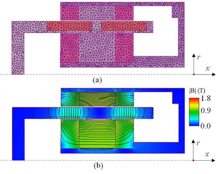
The model of the linear motor is shown in Figure 5. This model is a two-dimensional transient
finite element model with a motion region. At this point, the mover is in the middle of the stroke, and
The model
The model of of the
the linear
linear motor
motor is
is shown
shown in
in Figure
Figure5.
5. This
This model
model is is aa two-dimensional
two-dimensional transient
transient
the position is defined as the original point of the mover, as shown in Figure 5. The magnetic field is
finite element
finite element model
model with
with aa motion
motion region.
region. At
At this
this point,
point, the
the mover
mover isis in
in the middle
middle of
of the stroke,
stroke, and
and
mainly distributed in ferromagnetic materials, and the leakage flux is relatively small. In order to
the position is defined as the
the the original
original point
pointof
ofthe
themover,
mover,asasshown
shownininFigure
Figure5.5.The
Themagnetic
magnetic field is
field
display the internal structure, the meshes in the air box of the calculation region are hidden.
mainly
is mainly distributed
distributedininferromagnetic
ferromagneticmaterials,
materials,and
andthe
theleakage
leakageflux
flux isis relatively
relatively small. In order to to
display the
display the internal
internal structure,
structure, the
the meshes
meshes in
inthe
theair
airbox
boxofofthe
thecalculation
calculationregion
regionare
arehidden.
hidden.
Figure 5. Finite element model of the linear motor, (a) mesh, (b) flux density.
Figure 5. Finite element model of the linear motor, (a) mesh, (b) flux density.
Figure 5. Finite element model of the linear motor, (a) mesh, (b) flux density.
3.2. Combined Simulation Model
3.2. Combined Simulation Model
3.2. Combined
In order to Simulation
analyze the Modelelectromagnetic loss of the designed PWM rectifier, its physical model is
In orderbytousing
established analyzethethe
powerelectromagnetic
electronics toolboxloss of in
thethe
designed
software PWM rectifier, its
of MATLAB. physical model
Supported by the
is In order
established to analyze the electromagnetic loss of the designed PWM rectifier, its physical model is
finite element by using the
software we power
used toelectronics
create the toolbox
model of inthe
thelinear
software of MATLAB.
motor, Supported
the finite element by the
model of
established
finite element bysoftware
using the wepower toelectronics
used into create toolboxofin
the model thethe software
linear motor,ofthe
MATLAB.
finite Supported
element model by the
the
the linear motor is embedded the MATLAB software. The MATLAB software calls the of
finite
finite
linear element
motor software
is embedded we used to create the model of the linear motor, the finite element model of
element software in every into
timethe MATLAB
steps, software.
so the real The MATLAB
combined simulationsoftware calls the finite element
can be realized.
the linear
software motor
in every is embedded into the MATLAB software. The MATLAB software calls the finite
As shown in time steps,
Figure so the
6, the real combined
combined simulation
model consists can be
of four realized.
parts: linear motor finite element
element
As software
shown in in every6,time
Figure the steps,
combined so the real combined
model consists ofsimulation
four parts:can be realized.
linear motor finitecontroller
element
model, rectifier model, rectifier controller, and free-piston engine model. The rectifier
model, As shown
rectifier in Figure
model, 6, the
rectifier combined
controller, model
and consists
free-piston of four
engineparts:
model.linearThemotor finite
rectifier element
controller
provides PWM signals to the four power switch devices of the rectifier model. The PWM signals are
model, rectifiersignals
provides model, rectifier controller, anddevices
free-piston engine model.
model.The rectifier controller
calculatedPWM based on the to the four
current powerof
feedback switch
the motor, andofa the rectifier
discrete proportional The PWMdifferential
integral signals are
provides PWM signals to the four power switch devices of the rectifier model. The PWM signals are
calculated based on the current feedback of the motor, and a discrete proportional
(PID) algorithm is used in this paper. The free-piston engine model is created according to the integral differential
calculated based on the current feedback of the motor, and a discrete proportional integral differential
(PID) algorithm
difference is useddescribed
equations in this paper. The The
in [16]. free-piston engine
free-piston modelmodel
engine is created according
is used to thethe
to output difference
piston
(PID) algorithm is used in this paper. The free-piston engine model is created according to the
equations described in [16]. The free-piston engine
motion trajectory to drive the linear motor finite element model. model is used to output the piston motion trajectory
difference equations described in [16]. The free-piston engine model is used to output the piston
to drive the linear motor finite element model.
motion trajectory to drive the linear motor finite element model.
Figure 6. Combined model of the linear motor system.
Figure 6. Combined model of the linear motor system.
Figure 6. Combined model of the linear motor system.A prototype of the linear motor system designed in the last section is developed. Figure 7 shows
the prototype and its test platform. The test platform consists of five parts: the developed linear motor,
prototype, the developed PWM rectifier, an air spring, a free piston engine and a battery.
The piston bore of the engine is 48 mm with the max stroke of 38 mm and the effective
compression ratio of 7.8. It uses gasoline direct injection and spark ignition combustion under the
Electronics 2020, 9, 621 7 of 11
excess air ratio of 1.1. The indicated power of the engine is about 1.5 kW, and the indicated thermal
efficiency is 37% [17]. The piston bore of the air spring is 65 mm, which is bigger than the piston bore
Electronics 2020, 9, x FOR PEER REVIEW 7 of 11
3.3.ofModel
the engine. The moving mass of both the piston and cylinder is about 0.5 kg.
Validation
A displacement sensor is connected to the mover of the linear motor, and a current sensor is
3.3. Model Validation
A prototype of the linear motorside
system designed
installed in the alternating current of the rectifier, in
sothe
the last section
real-time is developed.
piston-mover Figureand
position 7 shows
the
thecoil
prototypeA and
prototypeits test
of platform.
the linear The
motor test platform
system consists
designed in theof five
last parts:
section the
is developed
developed.
current of the linear motor can be tested. Based on the test platform, the combined model created linear
Figure 7 motor,
shows
prototype, lastthe
in the prototype developed
section and PWM
its test
is validated rectifier,
platform.
by Thean
comparing air
test spring,
platform
the simulated a free
consistspiston engine
of five
results withparts: anddeveloped
the a battery.
the prototype testedlinear motor,
results.
prototype, the developed PWM rectifier, an air spring, a free piston engine and a battery.
The piston bore of the engine is 48 mm with the max stroke of 38 mm and the effective
compression ratio of 7.8. It uses gasoline direct injection and spark ignition combustion under the
excess air ratio of 1.1. The indicated power of the engine is about 1.5 kW, and the indicated thermal
efficiency is 37% [17]. The piston bore of the air spring is 65 mm, which is bigger than the piston bore
of the engine. The moving mass of both the piston and cylinder is about 0.5 kg.
A displacement sensor is connected to the mover of the linear motor, and a current sensor is
installed in the alternating current side of the rectifier, so the real-time piston-mover position and the
coil current of the linear motor can be tested. Based on the test platform, the combined model created
in the last section is validated by comparing the simulated results with the prototype tested results.
Figure7.7.Prototype
Figure Prototypeof
ofthe
the linear
linear motor systemand
motor system andits
itstest
testplatform.
platform.
The piston
Figure bore ofthe
8 shows thesimulated
engine is 48andmm withmovement
tested the max stroke
of theof 38 mm and the
piston-mover effective
assembly. Ascompression
shown in
ratio
theoffigure,
7.8. It auses gasolinetesting
simplified directcycle
injection and spark
is used. ignition
The stroke combustion
of the under
testing cycle is the excess
14 mm, airthe
and ratio
of reciprocating
1.1. The indicated power
frequency of the
is about 23engine
Hz. Theistesting
about cycle
1.5 kW,
hasandtwo the indicated
processes. thermal
In the efficiency
first process, the is
37%linear
[17].motor worksbore
The piston in motoring
of the air mode,
springthe
is 65 PWMmm,rectifier
which isworks
biggerasthan
an PWM inverter
the piston boretoofdrive the
the engine.
Thelinear
movingmotormassmove from the
of both top piston
to bottom,
and and the gas
cylinder spring0.5
is about brakes
kg. the motion. In the second process,
theAgas spring drivessensor
displacement the linear motor move
is connected from
to the bottom
mover oftothe
top, the PWM
linear motor, rectifier
and a works
currentin sensor
rectify is
and boost mode, and the linear motor works in generating mode to brake the motion.
installed in the alternating current side of the rectifier, so the real-time piston-mover position and the
coil current of the linear motor can be tested. Based on the test platform, the combined model created
Figure 7.
in the last section is validated byPrototype
comparing of thethelinear motor system
simulated resultsand its test
with theplatform.
prototype tested results.
Figure 8 shows the simulated and tested movement of the piston-mover assembly. As shown
Figure 8 shows the simulated and tested movement of the piston-mover assembly. As shown in
in the figure, a simplified testing cycle is used. The stroke of the testing cycle is 14 mm, and the
the figure, a simplified testing cycle is used. The stroke of the testing cycle is 14 mm, and the
reciprocating frequency is about 23 Hz. The testing cycle has two processes. In the first process,
reciprocating frequency is about 23 Hz. The testing cycle has two processes. In the first process, the
the linear motor works in motoring mode, the PWM rectifier works as an PWM inverter to drive the
linear motor works in motoring mode, the PWM rectifier works as an PWM inverter to drive the
linearlinear
motor move
motor fromfrom
move top top
to bottom, andand
to bottom, thethe gasgas
spring
springbrakes
brakesthe
themotion.
motion.In Inthe
the second process,
second process,
the gas
thespring drives
gas spring the linear
drives motor
the linear movemove
motor fromfrombottom to top,
bottom to the
top,PWM
the PWM rectifier works
rectifier in rectify
works and
in rectify
boostandmode, and the linear motor works in generating mode to brake
boost mode, and the linear motor works in generating mode to brake the motion. the motion.
Figure 8. Comparison of tested and simulated movement.
Figure 8. Comparison of tested and simulated movement.
Figure 8. Comparison of tested and simulated movement.Electronics
Electronics 2020,
2020, 9, x FOR PEER REVIEW
9, 621 8 8of of
11 11
Electronics 2020, 9, x FOR PEER REVIEW 8 of 11
Figure 9 shows the simulated and tested coil current of the linear motor during the testing cycle.
Figure
Figure
In each 9 shows
9 shows
stroke, thethe the
coil simulated
simulated
current isandand tested
tested
controlled coil
coil
to current
current
standard ofof the
the
sine linear
linear
wave motor
motor
by during
theduring
PWM thethe testing
testing
rectifier. cycle.
cycle.
The root
In each
Inmean
each square (RMS) currents in the two processes are 16.8 A and 9.8 A. The difference betweenroot
stroke,
stroke, the the
coil coil current
current is is controlled
controlled to to
standardstandard
sine sine
wave wave
by the by
PWM the PWM rectifier.
rectifier. The rootThe
mean the
mean
square square
(RMS) (RMS)
currents currents
in the two in the two
processes processes
are 16.8 A are
and 16.8
9.8 A
A. and
The 9.8 A. The
difference
two RMS currents is due to the losses during the reciprocating motion cycle, including the difference
between thebetween
two RMS the
two
currentsRMS
is duecurrents
to the is
losses due to
during the
the losses during
reciprocating
electromagnetic loss discussed in the paper and the mechanical loss. the
motion reciprocating
cycle, motion
including the cycle, including
electromagnetic the
loss
electromagnetic
discussed in the paperloss and
discussed in the paper
the mechanical loss.and the mechanical loss.
Figure
Figure 9. 9. Comparison
Comparison of of tested
tested and
and simulated
simulated current.
current.
Figure 9. Comparison of tested and simulated current.
Figure
Figure1010shows
shows thethe
simulated
simulated and
and tested
testedPWM
PWM ratio ofof
ratio thethe
PWMPWM rectifier during
rectifier during thethe
testing
testing
cycle. Figure
cycle.As
Asshown10 shows
shown thethe
ininthe simulated
figure,
figure, the and are
theresults
results tested PWM ratio
areconsistent,
consistent, of the PWM
especially
especially when rectifier
when during
the linear motorthe testing
system
system is
cycle. As
is operating shown
operating inin the in
the powerthe figure,
power generation the results
generation state. are
state. This consistent,
This consistency especially
consistency validates when
validatesthe the linear
the combined
combinedmodel motor system
modelcreated
created in is
operating
inthe
thelast in the
lastsection, power
section,and generation
andindicates
indicatesthat state.
thatthe
the This
most
most consistency
electromagnetic
electromagnetic validates
loss
loss of ofthe
thethe combined
linear
linear model
motor
motor created
system
system hashas in
been
themodeled
been last section,
modeled by by and
thethe indicates
combined
combined that the
model,
model, most
soso electromagnetic
thecombined
the combined modelloss
model has of the linear
enough
enough motortoto
precision
precision system
carry has
carryoutout been
the
the
modeled by
electromagnetic
electromagneticthe
losscombined
analysis
loss analysis model,
in in
thethe so
next the combined
section.
next section. model has enough precision to carry out the
electromagnetic loss analysis in the next section.
Figure 10. Comparison of the tested and simulated PWM ratio.
Figure 10. Comparison of the tested and simulated PWM ratio.
4. Electromagnetic LossFigure 10. Comparison of the tested and simulated PWM ratio.
Analysis
4. Electromagnetic Loss Analysis
Based on the validated
4. Electromagnetic model in the last section, the electromagnetic loss and power conversion
Loss Analysis
Based
efficiency on linear
of the the validated modeldesigned
motor system in the lastfor
section,
the FPEG the are
electromagnetic
simulated andloss and power
analyzed conversion
in this section.
Basedof
efficiency
Considering onthe
that the
thevalidated
linear
linear model
motor
motor in the
system
system last section,
designed
works infor the FPEG
the electromagnetic
generating are simulated
mode all theloss
timeand
and power
analyzed
during conversion
the in this
stable
efficiency
running of the
section.ofConsidering linear
the FPEG, a that motor system
the linear
standard designed
cyclemotor system
is designed for
works
firstly the FPEG are
in generating
according simulated
to the mode and analyzed
all the time
rated operating duringin this
conditions the
section.
ofstable
the FPEG. Considering
running
As shown that
of the in the
FPEG,
Figurelinear
a 11, motor
standard system
cycle
the linear works
is designed
motor in generating
firstly in
system works mode
according
generating all the
to the
mode time
rated during
timethe
operating
all the
stablethe
during running
conditions of theofFPEG.
standard the FPEG,
cycle. As
The a standard
shown
working cycle
in Figure 11,isthe
frequency designed
of linear
the firstlysystem
motor
standard according
cycle is worksto in
50 Hz, the rated
generating
which operating
is equal mode
to
conditions of the FPEG. As shown in Figure 11, the linear motor system works
all the time during the standard cycle. The working frequency of the standard cycle is 50 Hz, which in generating mode
all the time during the standard cycle. The working frequency of the standard cycle is 50 Hz, whichElectronics
Electronics 2020,
2020, 9, x FOR PEER REVIEW
9, 621 9 9ofof
1111
Electronics 2020, 9, x FOR PEER REVIEW 9 of 11
is equal to 3000 turns per minute of conventional engines. The coil current amplitude of the linear
3000 turns
is motor
equal per
is 22
to minute
A,
3000 and of
turnsthe
perconventional
reciprocating engines.
stroke of The
minute of conventional coil current
theengines. Theamplitude
piston-mover movement
coil of amplitude
current the
is 36linear
mm. motor
of theislinear
22 A,
and the reciprocating stroke of the piston-mover movement is 36 mm.
motor is 22 A, and the reciprocating stroke of the piston-mover movement is 36 mm.
Figure 11. Standard cycle for electromagnetic loss analysis.
Figure 11. Standard cycle for electromagnetic loss analysis.
Figure 11. Standard cycle for electromagnetic loss analysis.
Figure
Figure 1212 shows
shows thethe simulated
simulated instantaneous
instantaneous electromagnetic
electromagnetic loss loss
power power
in theinlinear
the linear
motormotor
of theof
the standard
Figure 12 cycle.
shows Between
the the
simulated losses, the
instantaneous copper loss of coil
electromagnetic accounts
loss for
power 87%
standard cycle. Between the losses, the copper loss of coil accounts for 87% of the total loss. The copper in of
the the total
linear loss.
motor The
of
copper
the loss
standard depends
cycle. on
Between the winding
the losses, wire
the diameter
copper loss and
of is
coillimited
accounts
loss depends on the winding wire diameter and is limited by the maximum allowable mass of the by the
for maximum
87% of the allowable
total loss. mass
The
of theloss
copper moving-coil,
moving-coil, depends
thus it isonthustheit winding
difficultis to
difficult
reduce. toThe
wire reduce.
eddyThe
diameter and
loss eddy
ofistheloss
limited of by
magnet theismagnet
the maximum
small, is small,
and and this
allowable
this helps helps
mass
prevent
the magnet from high temperatures and demagnetization. The eddy loss of the iron core is acceptable.is
ofprevent
the the magnet
moving-coil, thusfrom
it ishigh temperatures
difficult to reduce. and
The demagnetization.
eddy loss of the The
magneteddyis loss
small, of the
and iron
this core
helps
acceptable.
prevent
This indicates This
thatindicates
the magnet from
the thattemperatures
high
electrical the electrical
pure iron “DT4” pureis
and iron “DT4”choice
demagnetization.
a suitable is a suitable
The thechoice
for eddy for the iron
lossmaterial
core of the core material
and core
sheetsis
and sheets
acceptable. are
This not necessary.
indicates that The
the figure
electrical also
pureindicates
iron “DT4”that the
is a aluminum
suitable alloy
choice
are not necessary. The figure also indicates that the aluminum alloy is not a good choice for the shell foris not
the a
coregood choice
material
forsheets
and the shell
material, thematerial,
asare not
eddy asisthe
necessary.
loss eddyfigure
The
higher loss expected.
than isalso
higher than expected.
indicates that the aluminum alloy is not a good choice
for the shell material, as the eddy loss is higher than expected.
Figure 12. Electromagnetic loss in the linear motor.
Figure 12. Electromagnetic loss in the linear motor.
Figure 13 shows the simulated instantaneous electromagnetic loss in the rectifier of the standard
Figure 12. Electromagnetic loss in the linear motor.
cycle. It can be13seen
Figure shows thatthethesimulated
loss power of each MOSFET
instantaneous is different, and
electromagnetic loss init istherelated to their
rectifier of theworking
standard
states.
cycle. Take
It can
Figure the
13be first half
seen the
shows of the
thatsimulated cycle
the loss powerto analyze. The
of each MOSFET
instantaneous EMF and current
is different,
electromagnetic of
lossand the
in the linear
it isrectifiermotor
relatedof are
tothe
theirpositive,
working
standard
sostates.
the ItK3
cycle. canis controlled
Take betheseenfirst bythe
half
that PWM thesignals
ofloss and
cycle toof
power theMOSFET
analyze.
each others remain
The EMF andoff.
is different, The
current
and current
ofitthe flows motor
linear
is related past the
to theirarediode of
positive,
working
K1soallthe
states. theK3
Take time,
is and
first its
thecontrolledhalfloss isPWM
bythe
of the biggest.
cyclesignals When theothers
and the
to analyze. The K3
EMFPWM iscurrent
remain
and off,off.
theof current
Thethecurrent
linearflows pastpast
flows
motor thepositive,
are diode of
the diode
the K4,
soofthe
K1K3 and its
allisthe loss is the
time, andby
controlled second
itsPWM biggest.
loss issignals No
the biggest. current
When
and the flows
the K3
others past
PWMoff.
remain the K2
is off,during
Thethe the
current
current first half
flows
flows of
past
past the
thethecycle,
diode
diode
soof
of itsthe
K1 loss
all K4,
theis time,
zero.its
and Byloss
and analyzing
itsisloss the biggest.
theissecond
the results, we
biggest.
Whencanthe
No conclude
current
K3 PWM that
flows the
off, diodes
ispast K2 in
the current the
during rectifier
flows firstshould
thepast half
the ofbe
diodethe
improved,
ofcycle,
the K4, soandas they
its loss account
is zero.
its loss is theByfor most of
analyzing
second the loss
theNo
biggest. in the
results, PWM
currentweflows rectifier.
can conclude
past the K2 that the diodes
during in half
the first the rectifier
of the
should
cycle, be improved,
so its asBy
loss is zero. they account for
analyzing the most of the
results, we loss
can in the PWM
conclude rectifier.
that the diodes in the rectifier
should be improved, as they account for most of the loss in the PWM rectifier.Electronics
Electronics 2020,
2020, 9, x FOR PEER REVIEW
9, 621 1010ofof
11 11
Figure 13. Electromagnetic loss in the PWM rectifier.
Figure 13. Electromagnetic loss in the PWM rectifier.
Table 3 lists the main parameters and the efficiency of the linear motor system designed by this
Table
paper for 3 listsUnder
a FPEG. the main parameters
the standard and the
working efficiency
cycle of ratedoffrequency
the linear50
motor system
Hz and rateddesigned
stroke 36bymm,this
the generating efficiency of the linear motor and the power conversion efficiency of the rectifier are36
paper for a FPEG. Under the standard working cycle of rated frequency 50 Hz and rated stroke
mm,and
91.6% the generating efficiency The
94.1%, respectively. of the linear motor
efficiency of theand the power
linear conversion
motor system efficiency
is 86.3%. of the rectifier
Considering the
are 91.6% and 94.1%, respectively. The efficiency of the linear motor system is 86.3%. Considering
indicated thermal efficiency of engine is about 37% [17], the efficiency of the chemical-to-electrical the
indicated
energy thermalofefficiency
conversion about 31%ofcanengine is aboutby37%
be obtained the [17],
FPEGthe efficiency
system, whenofitthe chemical-to-electrical
uses the motor system.
energy conversion of about 31% can be obtained by the FPEG system, when it uses the motor system.
Table 3. Parameters and efficiency of the linear motor system.
Table 3. Parameters and efficiency of the linear motor system.
Name Value
Name Value
Rated motion frequency 50 Hz
Rated motion
Ratedfrequency
motion stroke 5036Hz
mm
Rated motion strokepower
Rated output 36540
mm W
Rated output power
Mass of the mover 540
1.2Wkg
Efficiency of
Mass of the moverthe linear motor 91.6%
1.2 kg
Efficiency of the rectifier 94.1%
Efficiency of the linear
Efficiency of the motor system 91.6%
86.3%
motor
Specific power of the motor 118 W/kg
Efficiency of the rectifier 94.1%
Efficiency of the motor
5. Conclusions 86.3%
system
In this paper, a linear motor system
Specific composed
power of the of a moving-coil linear motor with axial magnetized
118 W/kg
magnets and an H-bridge PWM rectifier motor is designed for a portable free-piston engine generator.
A combined electromagnetic simulation model is presented and validated by the prototype tested
results. The electromagnetic loss of the linear motor system is analyzed by using the validated model.
5. Conclusions
Under the rated working frequency of 50 Hz, the efficiency of 86.3% can be obtained by the proposed
In this paper, a linear motor system composed of a moving-coil linear motor with axial
linear motor system, which meets the requirement of the design.
magnetized magnets and an H-bridge PWM rectifier is designed for a portable free-piston engine
The electromagnetic analysis indicates that the copper loss is the main loss of the linear motor,
generator. A combined electromagnetic simulation model is presented and validated by the
and the diode loss is the main loss of the rectifier. The copper loss and the diode loss account for more
prototype tested results. The electromagnetic loss of the linear motor system is analyzed by using the
than 90% of the total loss. In the future, we will try to improve the performance of the linear motor
validated model. Under the rated working frequency of 50 Hz, the efficiency of 86.3% can be obtained
system by optimizing the moving-coil of the linear motor and using independent diodes to replace the
by the proposed linear motor system, which meets the requirement of the design.
internal diode of the MOSFET. We will test the efficiency of the linear motor system under the 50 Hz
The electromagnetic analysis indicates that the copper loss is the main loss of the linear motor,
rated working cycle after manufacturing a more powerful mechanical drive system.
and the diode loss is the main loss of the rectifier. The copper loss and the diode loss account for more
than 90% of the total loss. In the future, we will try to improve the performance of the linear motor
system by optimizing the moving-coil of the linear motor and using independent diodes to replace
the internal diode of the MOSFET. We will test the efficiency of the linear motor system under the 50
Hz rated working cycle after manufacturing a more powerful mechanical drive system.Electronics 2020, 9, 621 11 of 11
Author Contributions: Y.H. completed the model analysis and finished the manuscript; Z.X. designed the rectifier
and provided the guidance; L.Y. designed the linear motor and completed the test; L.L. revised the manuscript.
All authors have read and agreed to the published version of the manuscript.
Funding: This work is supported by the National Natural Science Foundation of China (NO. 51875290, 51975297).
Conflicts of Interest: The authors declare no conflict of interest.
References
1. Jia, B.; Zuo, Z.; Tian, G.; Feng, H.; Roskilly, A.P. Development and validation of a free-piston engine generator
numerical model. Energy Convers. Manag. 2015, 91, 333–341. [CrossRef]
2. Hanipah, M.R.; Mikalsen, R.; Roskilly, A.P. Recent commercial free-piston engine developments for automotive
applications. Appl. Therm. Eng. 2015, 75, 493–503. [CrossRef]
3. Woo, Y.; Lee, Y.J. Free piston engine generator: Technology review and an experimental evaluation with
hydrogen fuel. Int. J. Automot. Technol. 2014, 15, 229–235. [CrossRef]
4. Yang, L.; Xu, Z.; Liu, L.; Liu, N.; Yu, H. A Tubular PM linear generator with a coreless moving-coil for
free-piston engines. IEEE Trans. Energy Convers. 2019, 34, 1309–1316. [CrossRef]
5. Yan, L.; Zhang, L.; Jiao, Z.; Hu, H. Armature reaction field and inductance of coreless moving-coil tubular
linear machine. IEEE Trans. Ind. Electron. 2014, 61, 6956–6965. [CrossRef]
6. Tan, C.; Li, B.; Ge, W. Thermal quantitative analysis and design method of bi-stable permanent magnet
actuators Based on multi-physics methodology. IEEE Trans. Ind. Electron. 2019. [CrossRef]
7. Yu, X.; Li, B.; Zhang, T. Variable weight coefficient optimization of gearshift actuator with direct-driving
automated transmission. IEEE Access 2020, 8, 4860–4869. [CrossRef]
8. Wang, J.; West, M.; Howe, D.; Parra, H.; Arshad, W. Design and experimental verification of a linear
permanent magnet generator for a free-piston energy converter. IEEE Trans. Energy Convers. 2007, 22,
299–306. [CrossRef]
9. Xu, Z.; Chang, S. Improved moving coil electric machine for internal combustion linear generator. IEEE Trans.
Energy Convers. 2010, 25, 281–286.
10. Chen, H.; Liang, K.; Nie, R.; Liu, X. Three dimensional electromagnetic analysis of tubular permanent magnet
linear launcher. IEEE Trans. Appl. Supercond. 2018, 28, 1–6. [CrossRef]
11. Zheng, P.; Tong, C.; Bai, J.; Yu, B.; Sui, Y.; Shi, W. Electromagnetic design and control strategy of an axially
magnetized permanent-magnet linear alternator for free-piston Stirling engines. IEEE Trans. Ind. Electron.
2012, 48, 2230–2239. [CrossRef]
12. Xu, Y.; Zhao, D.; Wang, Y.; Ai, M. Electromagnetic characteristics of permanent magnet linear generator
(PMLG) applied to free-piston engine (FPE). IEEE Access 2019, 7, 48013–48023. [CrossRef]
13. Chen, H.; Zhao, S.; Wang, H.; Nie, R. A novel single-phase tubular permanent magnet linear generator.
IEEE Trans. Appl. Supercond. 2020, 30. [CrossRef]
14. Park, M.; Choi, J.; Shin, H.; Lee, K. Electromagnetic analysis and experimental testing of a tubular linear
synchronous machine with a double-sided axially magnetized permanent magnet mover and coreless stator
windings by using semi-analytical techniques. IEEE Trans. Magn. 2014, 50, 1–4. [CrossRef]
15. Shin, K.; Jung, K.; Cho, H.; Choi, J. Analytical modeling and experimental verification for electromagnetic
analysis of tubular linear synchronous machines with axially magnetized permanent magnets and flux-passing
iron poles. IEEE Trans. Magn. 2018, 99, 1–6. [CrossRef]
16. Yan, H.; Xu, Z.; Lu, J.; Liu, D.; Jiang, X. A reciprocating motion control strategy of single-cylinder free-piston
engine generator. Electronics 2020, 9, 245. [CrossRef]
17. Lu, J.; Xu, Z.; Liu, D.; Liu, L. A Starting control strategy of single-cylinder two-stroke free-piston engine
generator. J. Eng. Gas Turbines Power 2020, 142, 1–11. [CrossRef]
© 2020 by the authors. Licensee MDPI, Basel, Switzerland. This article is an open access
article distributed under the terms and conditions of the Creative Commons Attribution
(CC BY) license (http://creativecommons.org/licenses/by/4.0/).You can also read