Co-generation technology: the key to a more fuel-efficient proportioning system
←
→
Page content transcription
If your browser does not render page correctly, please read the page content below
Co-generation technology: the key to a more
fuel-efficient proportioning system
w h i t e pa p e r
Abstract
Used to apply polyurethane foam or polyurea, the Graco® integrated series of ReactorTM
proportioning systems (Figures 1 and 2) combines a proportioner with a diesel generator.
It is the first heat-as-you-go polyurethane application equipment that uses co-generation
technology to improve spraying performance and save diesel fuel.
The idea for the new integrated system grew out of recognizing the need for smaller, more
fuel-efficient proportioning systems. It was clearly desirable to lower the entry and operating
costs for the portable spray rig owner, yet still provide the same level and quality of system
output.
In using co-generation technology, the focus of the Graco design team became three-fold:
develop a complete, portable, fuel-efficient system; design a better user interface and system
controls; and improve or maintain the same level of spray performance.
Co-generation is a method to generate both heat and electricity from a single power source.
This new integrated system uses a dual coolant loop to capture waste heat from the generator Figure 1 – The integrated Reactor system
coolant system. The heated coolant is metered to heat exchangers that warm the material on shown with an optional air compressor
an as-needed basis. The system results in a 25% improvement in temperature rise, compared
to a standard Reactor unit. The heating system is regulated by proprietary software, ensuring
rapid temperature rise and accurate control. Since electric heaters can be eliminated for
most foam applications and significantly reduced in size for polyureas, the integrated system
uses a smaller, more fuel-efficient generator. Calculations show, and field testing confirms,
significant fuel savings—up to 50% per year in some cases. The new series of proportioners
is a completely engineered solution with reduced electrical consumption, improved heating
capacity, and advanced controls – representing innovation in operation, productivity and
efficiency.
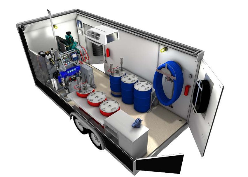
Figure 2 – Shown from back side,
the palletized system includes an
integrated generator
Author:
Arthur T. Graf
AFTD Electrical Design Engineer
Graco Inc.
For more information, visit us at www.graco.com
PROVEN QUALITY. LEADING TECHNOLOGY. 1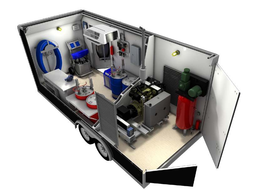
Design Considerations
A standard Graco Reactor proportioner operates with standard independent devices, such as an
air compressor, generator, breathing air system, supply pumps, and other auxiliary equipment.
Because joining the generator with the Reactor would significantly change the way a complete
proportioning system would be built and operated, considerable effort went into developing a
system that would blend well with customer and distributor expectations. The Graco engineering
team determined three key design requirements for operating a complete proportioning system:
electrical power and air requirements, system form factor, and usability considerations.

Electrical Power and Air Requirements
Electrical power and air requirements form the foundation for how the Reactor
proportioner operates. In considering design goals, the team determined where
to affect the greatest increases in system power efficiency.
Electrical loads in a portable proportioning system (see Figure 3) include:
1.	Reactor electric motor and fluid heaters
2. Air compressor
3. Air dryer
4. Breathing air
5. Lights
6. Band or blanket heaters                                                                                    610 c
                                                                                                                   m
7.	Heating or air conditioning                                                                7
                                                                              1                           4
These loads can be broken down into base-system
(1 through 4) and auxiliary loads (5 through 7).                                                                      5
As for compressed air, the following pneumatic                                          11
                                                                    10
loads are required for system operation:
                                                                                                      9
8. Supply pumps                                                                           3
                                                                              8
9. Agitator(s)                                                                                    6

10. Gun air
                                                                                                                          2
11. Breathing air

                                                    Figure 3 – Standard devices that support a typical
                                                    portable proportioning system

                                                For more information, visit us at www.graco.com

                                     PROVEN QUALITY. LEADING TECHNOLOGY.                                                      2
Since compressed air power is derived from electrical power, the system optimization became
two tiered: how could compressed air loads be reduced and how could electrical loads be
reduced, yet keep the same functionality? The ability to reduce these loads would directly affect
the choice of engine and generator size for the integrated Reactor system.
In researching and optimizing the compressed air loads, the team found that high-pressure
breathing air systems require significant volumes of air, so they decided to only support a two-
mask low-pressure breathing air system. Optimal agitator speeds for various materials were
researched since the amount of air used is directly proportional to agitator speed.
The team devised a way to limit the volume of air supplied to the agitator to reduce the chance of
overloading a smaller air compressor.
When it came to electrical loads, the primary goal of the project came into play: reduce or
eliminate fluid heater electrical power requirements by capturing waste heat from the engine.
Another goal was to limit peak in-rush currents drawn by the cycling of the air compressor
by using a compressor with a continuous-run head unloader. Other power requirements were
difficult to reduce, except through recommendations made to the contractor, such as using lower
wattage blanket heaters instead of band heaters to condition their material.

System Form Factor
The second key design area that the engineering
team focused on was system form factor.
The goal was to develop a system package that could
be palletized and fit in a trailer, box truck, or cargo
van (see Figure 4). Size and weight were critical to                                                    610 c
                                                                                                             m
meet this goal.

                                                          Figure 4 – Graco’s integrated proportioning
                                                          system saves space in spray rigs, eases
                                                          installation, and uses less fuel to operate

                                                 For more information, visit us at www.graco.com

                                      PROVEN QUALITY. LEADING TECHNOLOGY.                                        3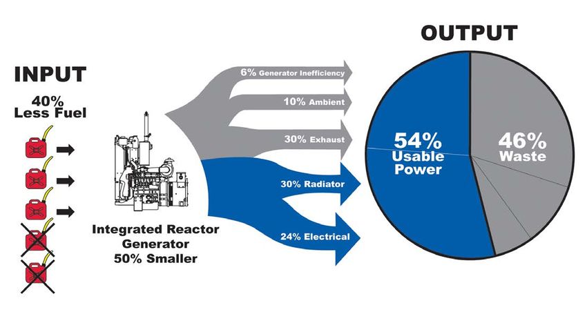
Additionally, when distributors assemble spray rigs, they often place the generator in its own
dedicated space to maximize engine ventilation and reduce noise. Although the new integrated
system permits trailer/truck designs without a wall since the smaller engine produces less
noise, the system allows a wall to be added between the engine and the proportioner if desired
by the customer. A minimal amount of duct work from the trailer wall to the engine’s radiator
is all that is required for proper engine cooling. This brings the added benefits of reduced
material cost and trailer build time.

Usability Considerations
The third key design area, usability and human factors, required a look at system service and
repair as well as day-to-day system control. The end-user can access system controls for an
air manifold, the engine, and the proportioner all in one convenient place. The layout of the
engine and proportioner takes into account system service and repair where, for example, the
chemical Y-strainers are raised to a more accessible height and include material feed pressure
and temperature gauges. The new electrical enclosure design brings most proportioner wiring
and auxiliary load wiring into a well-organized space, and simplifies diagnostics and repair.
This also eliminates the cost of a separate circuit breaker panel for auxiliary electrical loads.

New Technologies Bring Benefits
The new integrated series of Reactor proportioners brings new technologies to portable
polyurea and foam application systems. The biggest upgrades for contractors are co-
generation and the related benefits of using of a smaller diesel generator, improvements to
software control of temperature and pressure, and a completely redesigned electronic user
interface.

Co-generation Technology Saves Fuel
Diesel engines, like all energy conversion equipment, are only partially efficient. As seen in
Figure 5, roughly 30% of the energy put into a diesel engine is available to do mechanical
work. Of this 30%, only 80% is turned into electrical energy due to generator inefficiencies.
Roughly 76% of the fuel’s energy is lost.

                                                For more information, visit us at www.graco.com

                                     PROVEN QUALITY. LEADING TECHNOLOGY.                            4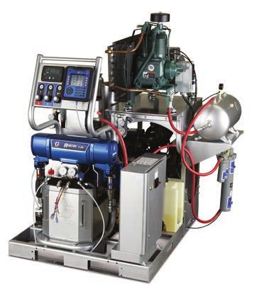
Figure 5 – Standard diesel
This is where the premise behind co-generation significantly benefits system efficiency and      generator efficiency
fuel savings. As previously discussed, co-generation refers to the production of both usable
heat and electricity from the same power source. Because of reduced power requirements, a
smaller generator was chosen that produced both enough power for electrical and compressed
air loads, and provided enough excess heat to the radiator to heat the two material
components sprayed by the proportioner. Co-generation provides essentially the same total
usable output energy as the standard generator configuration, but with a significant reduction
in input energy (fuel). (See Figure 6 on Page 6.)

                                              For more information, visit us at www.graco.com

                                    PROVEN QUALITY. LEADING TECHNOLOGY.                                                       5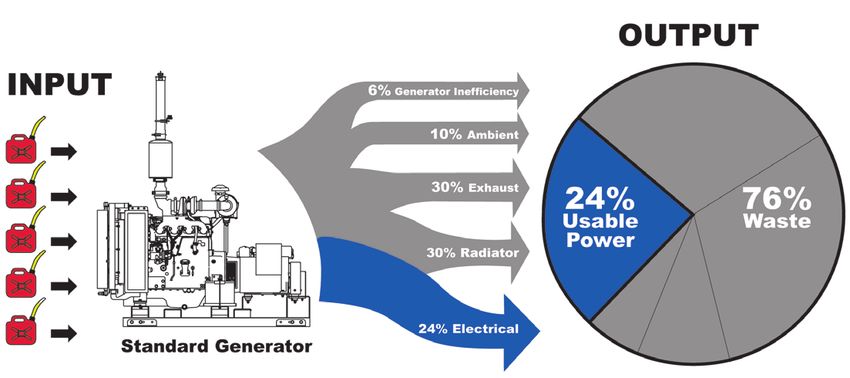
Of particular interest: fuel savings primarily comes from removing the large electrical            Figure 6 – Co-generation’s benefit:
load of the material heaters and not from reducing the generator size. It can be shown that        less fuel into a smaller generator
the 22kW generator on the new integrated system uses less fuel than a standard Reactor             provides similar power output as
                                                                                                   from a larger generator
proportioner powered by a 20kW generator. Note that fuel usage is proportional to the engine’s
mechanical load, not to the engine size.
In standard portable proportioner rigs, heat rejected from the engine’s radiator is a by-product
of generating usable mechanical/electrical power. The integrated Reactor proportioner has a
significant advantage: it captures this by-product as usable energy in addition to lowering the
mechanical/electrical energy requirements of the proportioner system.
Fuel savings follow. This makes the previous example clearer: the 22kW generator is operating
at 25 to 50% of mechanical load on a regular basis while the 20kW is operating near 100% to
keep up with the additional electrical heater load.

                                               For more information, visit us at www.graco.com

                                     PROVEN QUALITY. LEADING TECHNOLOGY.                                                                 6
Heat that is usually lost through the radiator is captured from the engine’s coolant and
transferred to the material through a set of three heat exchangers and two coolant loops.
Referring to Figure 7, heat is pulled from the engine coolant loop in heat exchanger 1 and
transferred to the secondary coolant loop. The secondary loop holds the transferred heat in
reserve until the Reactor calls for one or both materials to increase in temperature. In addition,
it prevents the possibility of material leaking into the engine if a heat exchanger were to fail.
Software control operates the three valves in the secondary loop, metering hot coolant through
the A and B heat exchangers to carefully control the temperature of the material available from
the proportioner. Excess heat that is not required to heat the material is removed from the
engine through the radiator.

                                                                                                     Figure 7. Heat capture and transfer
                                                                                                     from engine coolant to material

                                                For more information, visit us at www.graco.com

                                     PROVEN QUALITY. LEADING TECHNOLOGY.                                                                   7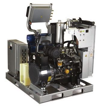
It should be noted that the heat exchanger system heats up the materials to a maximum
of 60°C. If additional heat is needed, optional electric booster heaters can bring the material
temperature to a maximum of 82°C. The best heat transfer is achieved with an appreciable
temperature difference between the material and coolant. Engine coolant is typically 94°C ,
resulting in only a 11°C difference when the material temperature setting is 82°C .
It is likely, at high material flow rates, the small temperature difference would result in lower
heat transfer, allowing the material temperature to drop below the 82°C set point. The addition
of a small 4-kilowatt electric booster heater allows the system to make up the additional
temperature change required for polyurea coatings. Despite this limitation, the system is
capable of up to 56°C of temperature change without the optional booster heater and 78°C
of temperature change with the optional booster heater, higher than the standard Reactor
proportioner. An added benefit of splitting the heat rise is that the material entering the
proportioner pumps is limited to a maximum temperature of 60°C, which retains expected
pump seal life. Using this method provides equivalent material temperature control and
repeatability compared with the standard Reactor proportioner, while still being significantly
more energy efficient.
Energy efficiency is only part of the equation. Compared to a typical spray rig’s 40 kilowatt
generator, we see significant benefits when it comes to weight, size and noise. The integrated
Reactor system pairs a 29 horsepower Perkins diesel engine with a 22 kilowatt Mecc Alte™
alternator. Table 1 contrasts a 40 kilowatt generator to the generator used in the integrated
Reactor system.

 Table 1. Advantages of the Integrated System Over a Standard System

                                                                                  Integrated
                               Generator on             Generator on             Compared to
                             Standard System         Integrated System             Standard

 Engine Horsepower                86 hp                    29 hp                  66% less

 Alternator Output                40 kW                    22 kW                  45% less

 Dimensions (LxWxH)         170 x 90 x 120cm          150 x 65 x 95cm            46% smaller

 Generator Weight                 860 kg                   320 kg                63% lighter

 Fuel Use Under                  5,7 ltr/h                3,4 ltr/h               40% less
 Average Load

                                                For more information, visit us at www.graco.com

                                      PROVEN QUALITY. LEADING TECHNOLOGY.                           8
Software Controls
New capabilities were developed as part of the integrated system’s new software controls.
For example, improved pressure control minimizes drops in pressure during pump changeover
– resulting in balanced static and dynamic (triggering) pressures for smooth spraying
performance. Another energy efficiency increase was realized by using an electric fan on the
engine radiator, instead of the typical belt driven option.
Through software control, this fan is cycled on and off to keep the engine and coolant
at consistent, optimum operating temperatures, instead of rejecting more heat energy than
necessary from the coolant as it passes through the radiator. Not only does the engine run
more efficiently, it allows for storing of engine heat in the coolant system for periods of high
material heat demand.
User Interface
The electronic user interface, called the Advanced Display Module (ADM), provides many
new tools and an intuitive layout for basic day-to-day operation (Figure 8). The ADM oversees
the network of control modules that operate the pump and heating systems, and monitors Figure 8 – The Advanced Display
system temperatures and pressures. More specific error codes are provided than on the Module provides an easy to use
standard Reactor, aiding system troubleshooting. Detailed troubleshooting steps are provided interface with detailed error codes,
on-screen for quick reference when an error is encountered. Data logging along with simple troubleshooting help, and data logging
USB downloads offers the end-user in-depth historical information about the application of the
material and system status.
The system can display the actual pressures of A and B materials simultaneously, helping
balance pressures at startup and aiding the troubleshooting process. Drum level estimation,
based on the number of pump cycles or strokes, can automatically shut down the proportioner
when the material supply drums are nearly empty. Material recipe storage is now possible for
users who spray multiple materials. The system also offers an optional remote display that can
place monitoring and control functions in the contractor’s hands — right at the gun.
For more information, visit us at www.graco.com
PROVEN QUALITY. LEADING TECHNOLOGY. 9Summary
The integrated series of Reactor proportioners provides several key benefits over a standard
mobile spray rig, while providing equal or better functionality compared to the standard
Reactor proportioner.
The system is a compact, completely turnkey solution. Installation is greatly simplified
with a pre-wired generator, electrical panel, and air control manifold. There is an optional air
compressor and air dryer that can come pre-installed on the system.
End-users can save significant fuel costs by using a smaller engine, utilizing the system’s co-
generation technology that heats A and B materials with less electricity. A fuel-use calculator
is available online to determine expected annual fuel savings with a sprayer’s required system
configuration.
Using a Graco Fusion® Gun 02 mix chamber, the system is capable of a 56°C change in
temperature and 78°C temperature change with added booster heat when starting at a 4°C
material supply temperature. Both heat material faster than standard Reactor proportioners.
With a new electronic display and controls, the contractor gets more detailed
error codes and advanced on-screen troubleshooting, USB flash drive job-data
downloads, visual indicators of drum fluid level, user settable pressure imbalance shutdown,
material recipe memory, and low material shutdown functions. A remote display located at the
gun is available as an option.
Improved pressure control provides consistent spray pressure at the gun. There is less
pressure drop between static and dynamic pressures as well as reduced pressure
fluctuation during pump changeovers. Biography
Overall, the contractor’s cost to spray material is lower, helping drive market growth – both for
material and its application. The significant time-saving and financial Arthur T. Graf
benefits of the integrated Reactor system clearly shows the power of joining Arthur Graf is an Electrical Design
co-generation technology with Graco’s proportioners.
Engineer for the Applied Fluid
Technologies Division of Graco Inc.
and works in Minneapolis, MN.
©
2012 Graco Inc. 348761ENEU Rev. A
10/12 All written and visual data contained
in this document are based on the latest
product information available at the time
of publication. Graco reserves the right to
make changes at any time without notice.
All other brand names or marks are used for
identification purposes and are trademarks
of their respective owners.
For more information, visit us at www.graco.com
PROVEN QUALITY. LEADING TECHNOLOGY. 10You can also read