Ro-Ro Kargo Gemisi İçin Tanımlanan Kurutuculu Buharlaşmalı Soğutma Sistemlerinin Termodinamik Analizi Thermodynamic Analysis Of Desiccant ...
←
→
Page content transcription
If your browser does not render page correctly, please read the page content below
DEÜ FMD 21(63), 733-740, 2019

Ro-Ro Kargo Gemisi İçin Tanımlanan Kurutuculu
Buharlaşmalı Soğutma Sistemlerinin Termodinamik Analizi
Thermodynamic Analysis Of Desiccant Evaporative Cooling
Systems Defined For Ro-Ro Cargo Vessel

Betül Saraç 1*
1Karadeniz Technical University, Sürmene Faculty of Marine Sciences - Naval Architecture and Marine Machines
Engineering, Trabzon,TÜRKİYE
Sorumlu Yazar / Corresponding Author*: bsarac@ktu.edu.tr

Geliş Tarihi / Received: 22.02.2019 DOI:10.21205/deufmd.2019216305
Kabul Tarihi / Accepted: 04.04.2019 Araştırma Makalesi/Research Article

Atıf şekli/ How to cite: SARAÇ, B. (2019). Ro-Ro Kargo Gemisi İçin Tanımlanan Kurutuculu Buharlaşmalı Soğutma Sistemlerinin Termodinamik
Analizi. DEUFMD, 21(63), 733-740.

Abstract
This study presents the results of the thermodynamic analysis of the new desiccant- evaporative-
air-cooling cycles can be applied in ships. The desiccant- evaporative- cooling system is
characterized by energy efficiency and low environmental impact. In this work, thermodynamic
possibility to install desiccant cooling system (DCS) has been studied for a M/V ASSTAR Trabzon Ro-
Ro cargo vessel, by using fraction of the heat rejected by existing on-board engine. The baseline
system is incorporated a desiccant dehumidifier, a heat exchanger, an indirect evaporative cooler,
and a direct evaporative cooler. The system offered sufficient sensible and latent cooling capacities
for a wide range of climatic, while allowing in flux of outside air in excess of what is typically
required for Ro-Ro cargo vessel. The present work aims at identifying the parameters of the system
cycle and investigates their effect on the performance of the waste-heat driven cooling systems. And,
the effect of different return air flow rates usage on the system performance is another aspect of the
study. Two ways are considered for mixing process of the return and outside air streams; one is
consists of two recirculation cycles, other one is a ventilation cycle, all of them have been examined
and demonstrated. The maximum coefficient of thermal performance (COP) of a waste-heat driven
cooling cycles were determined by assuming that the cycles are totally reversible.

Keywords: Dessicant, dehumification, indirect evoparative cooling, heat recovery IC engine

Öz
Bu çalışma gemilerde uygulanabilecek yeni nem almalı ve buharlaşmalı soğutma çevrimlerinin,
termodinamik analiz sonuçlarını sunmaktadır. Nem almalı buharlaşmalı soğutma sistemi, enerji
verimliliği ve düşük çevresel etkisi ile karakterize edilir. Bu çalışmada, gemide mevcut motor
tarafından atılan atık ısının bir kısmı kullanılarak, M/V ASSTAR Trabzon Ro-Ro kargo gemisi için
nem almalı ve buharlaşmalı soğutma sisteminin (DCS) termodinamik açıdan kullanılma olasılığı
incelenmiştir. Temel sistem nem alma cihazı, ısı eşanjörü, dolaylı buharlaştırıcı soğutucudan ve
doğrudan buharlaştırıcı soğutucudan oluşmaktadır. Sistem, çok çeşitli iklim koşulları için yeterli

 733
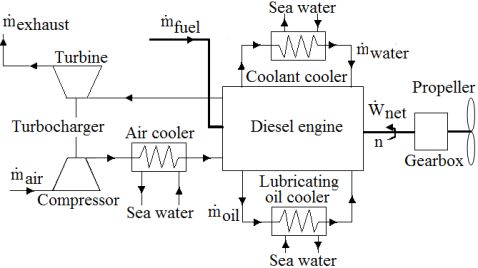
DEU FMD 21(63), 733-740, 2019 derecede duyarlı ve gizli soğutma kapasitesi sağlarken, Ro-Ro kargo gemisi için gerekli dış hava akışından daha fazlasını kullanımına imkan vermektedir. Bu çalışmada, sistem çevrim parametrelerini tanımlamayı ve bunların atık ısıyla çalışan soğutma sistemlerinin performansı üzerindeki etkilerini araştırmayı amaçlanmaktadır. Farklı dönüş hava debisi kullanımının sistem performansı üzerindeki etkisi de çalışmanın diğer bir özelliğidir. Geri dönüş havasının ve dış havanın karıştırılması için iki yaklaşım tanıtılmıştır; bunlardan biri iki farklı sirkülasyon çevrimlerinden oluşmakta iken, diğeri ise egzos çevrimi olmaktadır, hepsi de ayrı ayrı incelenmiş ve gösterilmiştir. Atık ısı ile çalışan soğutma çevrimlerinin maksimum ısıl performans katsayısı (COP), tanıtılan çevrimlerin tamamen tersinir çevrimler olduğu varsayılarak belirlenmiştir. Anahtar Kelimeler: Nem alıcı, nem alma, dolaylı buharlaşmalı soğutma, ısı geri kazanımlı IC motor 1. Introduction atmosphere the evaporation effect, the cold side fluid may be air, water or in the case of heat The main contributor to increasing atmospheric pipe refrigerant. The performance results of a carbon dioxide, concentration is the combustion thermally activated desiccant cooling system in of fossil fuels from the marine propulsion. The a combined heat and power application energy consumed heating, ventilating and air incorporating a reciprocating internal conditioning (HVAC) application in vessel combustion engine was presented by [7]. In the accounts for considerable amount of the total Eastern Black Sea, DEC systems were handled energy consumption. The effective use of energy by to use the waste heat from the furnaces of a is important in vessels. DCS uses recovered tea factory [8]. The study presents the results of energy from the waste energy produced by the the thermodynamic analysis of the introduced engine for air conditioning in marine cooling systems. application [1]. The performance evaluation on DCS helps the judgement of the improvement of It is the objective of this paper to demonstrate the use of energy and air quality. In general the thermodynamic advantage of a desiccant HVAC application, DCS may be utilized to reduce evaporative cooling system in the context of energy consumption or to replace conventional marine engine. In marine engine is refrigeration system [2 to 5]. implemented in the proposed system which provides a heat recovery opportunity for In order to to create comfortable cooled air regeneration of the desiccant dehumidifier. The conditions for the buildings with lowest energy specific objectives to be achieved in this study consumption and highest efficiency, a novel are as follows: indirect evaporative air cooler was developed and was patented as “Maisotsenko cycle”. A Demonstrate the cooling and thermodynamic novel heat and mass exchanger (HMX) performance of the system and its capability introduced for the Maisotsenko cycle which has to provide comfort for a marine course wet and dry sides of a plate like indirect climatic condition. evaporative air cooler components but using Thermal performance analyses for different air flow configurations creates assessment of different operating system different thermodynamic cycle [6]. configuration. Evaporative cooling is a technology that can 2. Material and Method substantially reduce the cooling energy requirement in the vessel. There are three types 2.1. Power system definition of the M/V of evaporative cooling process: Direct, indirect ASSTAR Trabzon Ro-Ro cargo vessel and indirect/direct. In direct evaporative The ship called M/V ASSTAR TRABZON cooling processes, the air is bought into direct considered in the study is a RO-RO cargo ship contact with water in the direct evaporative with a diesel engine. A Controllable Pitch cooler. Indirect evaporative cooling is achieved Propeller is used as propeller in the RO-RO by sensibly cooling a primary air stream cargo ship. The ship has 12-cylinder, through heat exchanger. Heat is transferred to a turbocharged ship diesel engine of the V-type secondary fluid on the cold side of the heat used as a single propulsion machine. Schematic exchanger, which ultimately rejects heat to 734
DEU FMD 21(63), 733-740, 2019
layout of the ship power system and energy different regeneration can be used as heating
flows are shown in Fig.1 and Fig.2, respectively sources for the air conditioning method.
and also technical specification of the diesel
 Table 2. Performance values of the diesel
engine is presented in Table 1. [9].
 engine system on 70% load ratio [9].
 MAK 12M 453 AK
 Mass flow of fuel 0,109 kg/s
 Mass flow of air 3,43 kg/s
 Air temperature 25 oC
 Mass flow of air 3,43 kg/s
 Air temperature 96 oC
 Mass flow of air 3,00 kg/s
 Air temperature 42 oC
 Mass flow of the sea water 12,80 kg/s
 Intake temperature of seawater 25 oC
Figure 1. Schematic layout of the ship power Mass flow of the sea water 12,80 kg/s
system [9]. Output temperature of seawater 28 oC
 Exhaust gass temperature 358oC
 Exhaust gass temperature 325 oC
 Mass flow of coolant 34,12 kg/s
 Coolant intake temperature 58 oC
 Coolant output temperature 68 oC
 Mass flow of lubricating oil 18,43 kg/s
 Lubricating oil intake temperature 48 oC
 Lubricating oil output temperature 54oC

 2.2. Description of Desiccant
 Evaporative Cooling System
Figure 2. Energy flows of MAK 12M 453 AK
turbo-diesel engine used for a M/V ASSTAR
 It can be stated, based on existing studies, that
Trabzon Ro-Ro cargo vessel. there is a major drawback in wider application
Table 1. Technical specification of the diesel of the desiccant-evaporative air conditioning
engine used in the vessel [9]. systems, since the coefficient of thermal
 performance (COP) of the systems (defined as
 MAK 12M 453 AK
 Type Four stroke
 obtained cooling capacity divided by required
 Configuration V type thermal energy for regeneration of the
 Number of cylinders 12 desiccant) are generally lower than 1.0.
 Cylinder bore 320 mm
 The purpose of the desiccant evaporative air
 Stroke high 420 mm
 Nominal engine speed 550 rpm
 cooling system is to use waste heat in some way
 Nominal power 2935kW for air cooling. In this system, the waste heat is
 Number of valves 24 intake+24exhaust used in a heat exchanger for heating the
 Flywheel direction Counterclockwise regeneration air. The regeneration air is used
 Injection order A1-B6-A4-B3-A2-B5 for drying the desiccant. After the humid and
 A6-B1-A3-B4-A5-B2 hot air from the atmosphere passes through the
The engine speed of the diesel engine having dehumidifier, the specific moisture decreases
turbocharger was kept constant at 550 rpm and and the temperature rises. The temperature is
different engine loads were obtained by then reduced by passing through a heat
changing the propeller blade angles. Engine exchanger. This air is then passed through an
load of 70%, was created at 180 propeller blade evaporative refrigeration unit to bring the space
angle. Measured performance value of the diesel to cooling conditions, whereby the specific
engine system load ratio is given in Table.2 [9]. humidity remains constant, the temperature is
The exhaust gas discharged from the gas reduced to the space temperature, and the
turbine was used to heat the regeneration air. relative humidity adjustment is provided by a
Other data given in Table 2 are given to show direct evaporation unit. Detailed descriptions
the other waste heat potential of the ship. The are given for the system described in Section
variety of waste heat is important to show that 2.3. The use of fans in the system and the use of

 735
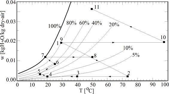
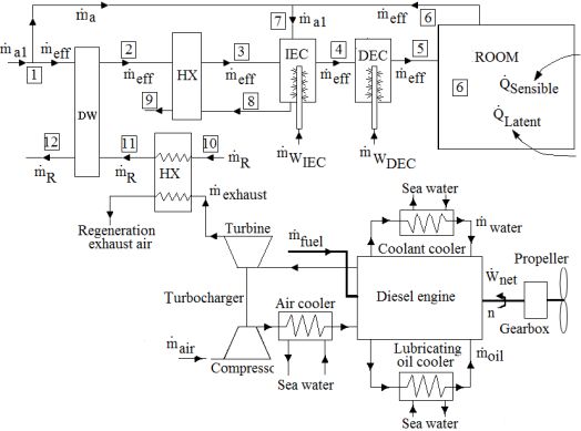
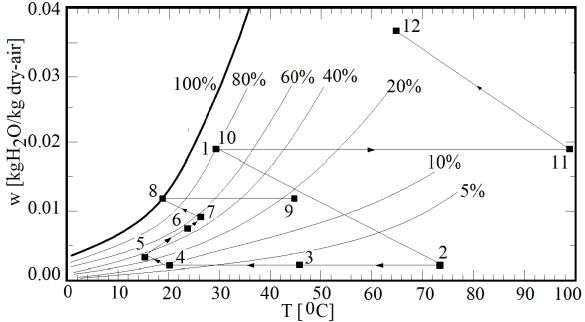
DEU FMD 21(63), 733-740, 2019
additional electric heaters in general causes the
oefficient of thermal performance (COP) to
drop. In the literature for the method is
indicated that Coefficient of thermal
performance (COP) is below 1 [10,11,12,13]. In
this study, the electrical energy used in the fans
is not considered. In addition, additional electric
heaters are not used.
2.3. System Configurations
The waste heat from the exhaust gas of MAK
12M 453 AK turbo-diesel engine is treated as a
thermal energy source for the proposed
desiccant cooling systems which can be applied
for the supply air entering the indoor space. As Figure 3.System schematics (Exhaust Heat
shown in Figure 3., the system under Recovery and model-1)
consideration consists of a power generation
MAK 12M 453 AK turbo-diesel engine, a
thermally activated rotary desiccant wheel
(DW), an air-to-air heat exchanger (HX), an
indirect evaporative cooler (IEC), and a direct
evaporative cooler (DEC) as a model 1. The
psychometric cycle of mode 1 is shown in Fig.4.
In operation (see in Fig.3 and Fig.4), the outdoor
air station-1 is divided for two streams, one for
IEC station 7 and other one for process air [1].
The air stream for IEC station-7 mixes with Figure 4. The psychometric cycle of model-1
return air station-6 in the ratio of 1:2. The
process air station-1 is heated up to condition of
station-2 by means of the desiccant wheel (DW)
while the specific enthalpy of the process air
remains constant until it reaches 0.03%
humidity. This condition can be set up in
accordance with the type of the desiccant to be
used. Then dehumidified and hot process air is
cooled by the air to air heat exchanger (HX). In
the HX, the sensible cooling is achieved for the
process air by using exhaust air from the IEC Figure 5. System schematics for model-2
station-8 having 100% humidity. The process
air at the exit of the IEC station-4 is cooled and
humidified until it reaches the supply air
condition station-5.
Then conditioned air enters the indoor space
station-6. The regeneration air station-10 is
heated up to station-11 by means of the hot
exhaust gases come from diesel engine using a
gas-to- air heat exchanger. This air station-11,
can be finally be used to regenerate the (DW).
After the regeneration, the air is exhausted and Figure 6. The psychometric cycle of the model-2
can be released at station-12. Other two
subsystems models of the desiccant cooling
system (model 2 and model 3) are defined to
satisfy the required conditions of the supply air
entering the indoor space, can be seen in Figure.
4 to through Figure. 8.

 736
DEU FMD 21(63), 733-740, 2019
 designing HVAC systems serving passenger
 cabins in ships [5]. In this study, the outdoor air
 condition with at 38◦C dry bulb and
 80%relative humidity was considered for the
 summer design condition. The design room air
 conditions used at 24◦C dry bulb and 50%
 relative humidity for the summer. The design
 conditions assumed for summer in this study
 should only be used in normal climate regions
Figure 7.System schematics for model-3 and not in extremely hot climates.
 The transmission heat gains and losses for each
 marine space surface can be calculated using
 Equation (1) [14]. The heat transmission
 between the cabins was neglected based on the
 assumption that the indoor air temperature in
 each cabin (i.e., 24 °C) was identical.
 = ∆ [( . ) + ( . )] (1)
 Where Kv is the heat transfer coefficient of the
 external surface in (W/(m2oC)) and Kg is the
Figure 8. The psychometric cycle of the mode-3 heat transfer coefficient of the external glass
 window in [W/(m2oC)]. Solar heat gain from
 windows and the deck are estimated in this
2.4. Methodology: Computational calculation. Av is heat transfer surface area for
application the deck Ag is the surface area of all windows.
The HVAC calculations are done by using mass The sensible and latent heat gains from a
continuity and the steady flow energy equations person exerting medium work were assumed to
with the help of the psychometric diagram. The be 70 W/person and 50 W/person, respectively.
waste heat used for the proposed systems is the For the lighting heat gain, fluorescent lighting
lowest thermal energy that is exhausted from equipment was assumed; the lighting
the diesel engine by exhaust gases. The exhaust equipment yielded a sensible heat emission of 8
air volume flow rate and the temperature limits W/m2. Two persons per square meter for the
to be used for the process air volume flow rate accommodation spaces and passenger cabins
to be conditioned can be ensured by the were considered in this study. Because of the
operating conditions of the diesel engine. Using high level of air-tightness in ship spaces, air
a gas-to-air heat exchanger, regeneration air infiltration and leakage in the cabin were
temperature can be reached 100 oC or higher by neglected while calculating the thermal load.
means of exhaust gases provided by diesel Table 3. lists the physical information of the
engine. The mass flow rate of the process air modelled cooling spaces.
and the mass flow rate of the regeneration air Table 3. Physical parameters of the model
are selected to be equal. Model 2 is defined as cooling space for calculating the thermal load.
the use of the recirculated air all over the IEC.
Model 3 is defined as the use of only a part of Space size Width is 16 m, Height is
 5m, Length is 5 m
the recirculation air in (IEC).Different return air Schedule on board At solar noon time
configuration effects on system performance Space conditions in 24 °C, 50%
has been aimed at. Summer
 Heat transfer surface ~400 m2
The operation modes of three systems are area
determined based on the outdoor air Window-to-deck ratio 15%
conditions, where the outdoor air is hot/warm Occupants People 10 (Sensible heat: 70
and very humid. The peak thermal loads of the W/person, latent heat: 50
cooled space were estimated using the W/person)
calculation method recommended by ISO-7547, The conventional constant air volume (CAV)
which utilizes the load calculation procedure systems are considered for three the desiccant-
and basic assumptions that are critical for evaporative air conditioning models in this

 737
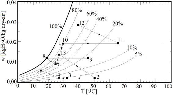
DEU FMD 21(63), 733-740, 2019 study. The energy consumption of the CAV humidity of the atmospheric air got high values. system for proposed models were calculated Similarly, it was observed that atmospheric air based on the defined peak cooling loads of the tended to reach maximum value of coefficient of model space in the ship. The indoor space thermal performance (COP) as dry cooling load is determined by means of the thermometer temperature increased. In sensible heat factor, SHF, is defined by the particular, when the relative humidity of the following equation: atmospheric air reached a value of 0.8, it was ̇ found that the coefficient of thermal = ̇ + ̇ (2) performance (COP) reached a maximum value and the coefficient of thermal performance Where ̇ stands for the room sensible cooling (COP) decreased when the drying temperature load and ̇ stands for the room latent cooling of the air was increased. In Model 3, it is seen load. The typical value of SHF is calculated to be from Figure 11 that as the drying temperature 0.7 for three models. of the atmosphere air increases and the relative ̇ = ̇ ( 5 − 4 ) (3) humidity increases, the coefficient of thermal performance (COP) of the system decreases ̇ = ̇ ℎ ( 5 − 4 ) (4) continuously and does not reach a maximum value. For Model 1, examples of typical values The total cooling load, ̇ , can be calculated obtained according to atmospheric air by conditions are; At 50% relative humidity, the ̇ = ̇ + ̇ (5) coefficient of thermal performance (COP) at 320 C was found to be 0.319. In Model 2, coefficient In order to evaluate the cooling performance of of thermal performance (COP) was calculated as the cooling system, the coefficient of 0.364 for the same atmospheric weather performance (COP), is considered on the based conditions and coefficient of thermal on thermal energy supply. performance (COP) for the Model 3 was 0.178. ̇ = ̇ (6) 0.32 Intake air (oC) 0.320 , 32 Model 1 30 The thermal energy supplied for the system is 0.31 28 26 used for the heating of the regeneration air COP COP 0.300 passed in the desiccant wheel. The thermal 0.30 Relative humidity () 0.8 energy supplied for the regenerative air flow Model 1 0.7 heating is given by the following equation, 0.6 0.5 0.29 0.280 0.4 0.5 0.6 0.7 0.8 0.9 26 28 30 32 ̇ , . = ( ̇ ) (∆ ) (7) Relative humidity ( ) Intake air Temperature (oC) Figure 9. Impact of intake air conditions on the system coefficient of thermal performance (COP) for model-1. 3. Results and Discussions The two proposed air stream mixing process for 0.34 0.34 Relative humidity ( ) the return air and out side air as a recirculation Model 2 0.8 0.7 cycles model-1 and model-3 and the exhaust air 0.33 0.6 stream considred to use directly in a 0.5 COP COP 0.32 ventilation cycle model-2 were examined and Intake air (oC) 32 0.32 results presented through Figures 9 to Figure 30 Model 2 11. The impact of the ambient air conditions on 28 26 the system coefficient of thermal performance 0.30 0.40 0.60 0.80 0.31 26 28 30 32 (COP) of three models, for a wide range of Relative humidity ( ) Intake air temperature (oC) ambient relative humidity at different dry bulb Figure 10.Impact of intake air conditions on the temperatures are presented in Figure 9 to system cooling performance (COP) for model-2. Figure 11. When Figure 9 and Figure 10 are examined, according to the results of Model 1 and Model 2, it was obtained that the coefficient of thermal performance (COP) values of the systems were reduced when the relative 738
DEU FMD 21(63), 733-740, 2019 0.18 0.20 HVAC applications for hot and humid climatic Model 3 Model 3 0.16 0.16 regions. References COP COP 0.14 0.12 Relative humidity ( ) [1] Singh, V.D. and Pedersen, E. (2016). A review of Intake air( oC) 0.8 0.12 32 0.08 0.7 waste heat recovery technologies for maritime 30 0.6 28 0.5 Application,. Energy Conversion and Management, 26 0.10 0.04 vol. 111, pp. 315-328. 0.4 0.5 0.6 0.7 0.8 0.9 26 28 30 32 DOİ:10.1016/j.enconman.2015.12.073 0196-8904. Relative humidity ( ) Intake air temperature (oC) [2] La, D., Dai, Y.J., Li, Y., Wang, R.Z. and Ge, T.S. (2010). Figure 11. Impact of intake air conditions on Technical development of rotary desiccant the system coefficient of thermal performance dehumidification and air conditioning: Areview, Renewable and Sustainable Energy Reviews, vol.14, (COP) for model-3. pp.130-147. DOİ:10.1016/j.rser.2009.07.016. Figure 12. shows the effect of different return [3] Panaras, G ., Mathioulakis, E., Belessiotis, V. (2011). Solid desiccant air-conditioning systems -design air flow rates usage on the system coefficient of parameters. Energy, vol.36, pp. 2399-2406. thermal performance (COP), for three models DOİ:10.1016/j.energy.2011.01.022. where the ambient air dry-bulb temperature [4] Panaras, G., Mathioulakis, E., Belessiotis, V. and changes between 25 to 38oC while relative Kyriakis, N. (2010). Theoretical and experimental humidity is kept constant as 0.80. It is seen that investigation of the performance of a desiccant air- conditioning system, Renewable energy, vol.35, Model 2 at given operation condition shows Issue. 7, pp. 1368-1375. DOI: better performance comparing other two model 10.1016/j.renene.2009.11.011. at the same intake air conditions while the [5] Napoleon, E. and Kunio, M. (2011). The role of cooling load increasing. Model 2 (ventilation the thermally activated desiccant cooling cycle) is most promising cycle and operational technologies in the issue of energy and system for HVAC applications for hot and humid environment. Renewable Sustainable Energy climatic regions. Reviews, vol.15, Issue. 4, pp. 2095-2122. DOI: 10.1016/j.rser.2011.01.013. 0.40 100 [6] Caliskan, H. Dincer, I. and Hepbasli, A. (2012). Exergoeconomic, enviroeconomic and sustainability 80 analyses of a novel air cooler. Energy and Buildings, 0.30 vol.55, 747-756. Cooling load [kW] = %80 DOI: 10.1016/j.enbuild.2012.03.024. 60 [7] Jalalzadeh-Azar, A.A., Slayzak, S. and Judkof, R. COP 0.20 Model 1 (2005). Performance assessment of a desiccant Model 2 Model 3 40 cooling system in a CHP application incorporating Cooling Load an IC engine. International Journal of Distributed 0.10 Energy Resources, vol.1, no.2, pp. 163-184. ISSN 20 1614-7138. [8] Saraç, B. (2017). Thermodynamic Analysis The 0.00 0 Usage of Air Conditioning Systems With 24 26 28 30 32 34 Ambient Temperature o C Dehumidifier and Evapoartive-Cooling Capabilities in Tea Plants. Dokuz Eylul University-Faculty of Figure 12.Effect of intake air conditions and Engineering Journal of Science and Engineering operational systems on the coefficient of Vol 19, Is. 57, pp. 927-937. thermal performance (COP), for three models. [9] Karaca, S. (2015). Determination Of Energy And Exergy Analysis Due To Different Angles Of Propeller Blades Of A Diesel Engine Vessel. Karadeniz Technical University, Trabzon. PhD 4. Conclusion thesis, Trabzon. [10] Löf, G.O.G, Cler, G. and Brisbane, T. (1988). Exhaust gases from MAK 12M 453 AK turbo- Performance of a Solar Desiccant Cooling System. diesel engine used for a M/V ASSTAR Trabzon Journal of Solar Energy Engineering. Vol. 110, pp. Ro-Ro cargo vessel, has a potential of waste heat 165-171. energy recovery in the field of the desiccant- [11] Sohani, A., Sayyaadi, H. and Hoseipoori, S. (2016). Modeling and multi-objective optimization of an M- evaporative air conditioning systems in cargo cycle cross-flow indirect evaporative cooler using vessel. Three case studies are introduced in this the GMDH type neural network. Int. Journal of study that shows the thermodynamic Refrigeration Vol.69, pp.186-204. possibilities of the desiccant-evaporative air [12] Charoensupaya, D. and Worek, W.M. (1988). conditioning systems applications in cargo Parametric Study of an Poen-Cycle Adiabatic Solid Desiccant Cooling System. Energy, Vol. 13, No.9, vessel. Model 2 (ventilation cycle) is most pp.739*747. promising cycle and operational system for 739
DEU FMD 21(63), 733-740, 2019
[13] Koronaki, I.P., Papoutsis, E.G. and V.D. COP Coefficient of thermal performance
 Papaefthimiou, V.D. (2016). Thermodynamic HVAC Heating, ventilating and air conditioning
 modeling and exergy analysis of a solar adsorption HMX Heat and mass exchanger
 cooling system with cooling tower in Mediterranean HX Heat exchanger
 conditions. Applied Thermal Engineering. Vol. 99, DW Desiccant wheel
 pp. 1027-1038. RO-RO Roll-on/roll-off
[14] Kreider, J.R., and Rabl, A. (1976). Heating and a Air
 Cooling of Buildings Design For Efficiency. Mc Graw R Rejeneration air
 Hill. ISBN 0-07-834776-9. eff Effektive
 K Heat transfer coefficient [W/(m2oC]
 Nomenclarature
 v External surface
 ̇ Mass flow rate (kg/s) g External glass window
 ̇ Heat transfer load (kW) A Heat transfer surface area
 h Enthalpy (kJ/kg) CAV Constant air volume
 Cp Specific heat (kJ/kgK) SHF Sensible heat factor
 w Humidity ratio [kg H2O/kg dry-air] S Sensible
 T Temperature (0C) L Latent
 DCS Desiccant cooling system DES Dessicant
 IEC Indirect evaporative cooler

 740
You can also read