GHBMC PEDESTRIAN MODEL OVERVIEW - Center for Injury Biomechanics - UNECE Wiki
←
→
Page content transcription
If your browser does not render page correctly, please read the page content below
GHBMC PEDESTRIAN MODEL
OVERVIEW

Full Body Model Center of Expertise
Wake Forest and Virginia Tech
Global Human Body Models Consortium
September 15th, 2020

 Center for Injury Biomechanics
 C I B
GHBMC Introduction
 - Objective & Mission
 Founded in 2006, GHBMC is an international consortium established to
 advance human body modeling technologies for crash simulations.

 MEMBERS
 OBJECTIVE: MISSION:
 To consolidate world- To develop and
 wide HBM R&D effort maintain high fidelity
 into a single global FE human body
 effort models for crash
 simulations

 SPONSOR PARTICIPANTS

9/15/2020 2
GHBMC Introduction
 - GHBMC COEs (Center Of Expertise)
 BRM (Body Region Model) COE FBM (Full Body Model) COE
 Co-PIs: Dr. Scott Gayzik
 Dr. Joel Stitzel
 Head Model COE Leader: Dr. Jay Zhao (JSS)
 PI: Dr. Liying Zhang; Leader: Dr. Jesse Ruan (Ford)
 Pedestrian & Active Model Test COE
 PIs: Dr. Costin Untaroiu
 Neck Model COE Thorax Model COE Dr. Andrew Kemper
 PI: Dr. Duane Cronin Leader: Dr. Eric Song (PSA), Dr. Jay Zhao (JSS)
 PI: Dr. Matt Panzer
 Leader: Dr. Maika Katagiri (JSS)
 Leader: Skye Malcolm (Honda)
 Models Conversion COE
 PIs: Dr. Hyung Yun Choi
 Leader: Dr. Eric Song (PSA)

 Abdomen Model COE Responsibilities:
 PI: Dr. Philippe Beillas
 Leader: Dr. Philippe Petit (Renault)
 FBM COE
 Pelvis & Lower • CAD mesh interface body
 Extremities Model
 COE regions
 PI: Dr. Matt Panzer • Full Body Validation
 Leader: Dr. Vishal Gupta (GM) BRM COEs
 • Body region validation
 • Suggest model design
 modifications
9/15/2020 • Updates 3
The GHBMC Family
 13 Base Models in the Family
 Developed in LS-Dyna, VPS, and Radioss

 Active Models Available

 C IB
GEOMETRY DEVELOPMENT

9/15/2020
 C IB 5
External Geometry Development
 • Procedures for determining
 external shape of body:
 • https://www.ncbi.nlm.nih.gov/p
 ubmed/22441664
 • Gayzik et al. 2012, “External
 landmark, body surface, and
 volume data of a mid-sized
 male in seated and standing
 postures”
 • We took landmark and surface
 data on living subjects who met
 sizes of interest

 C IB
Imaging Procedures: Upright MRI (aka uMRI)
 • We used upright MRI to scan the
 knee in the standing posture
 • We are not aware of other FEM
 human models that have used
 upright data for model
 development
 • The subjects were recruited and
 scanned for the purpose of
 human model development
 Gayzik, FS, Moreno, D.P., Hamilton, C.A., Tan, J.C., McNally, C.,
 Duma, S.M., Klinich, K.D., Stitzel, J.D., A multi-modality image
 data collection protocol for full body finite element analysis model
 development, SAE Technical Paper 2009-01-2261,
 doi:10.4271/2009-01-2261
 C IB
Upright MRI
 Table
 • Provides unique ability to Actual M50-O
 image oriented with gravity in the scanner

 • Protocol sequence:
 • Head
 Magnets g
 • Cervical
 • Seated Chest & Abd.
 • Standing Chest & Abd. Seat was
 • Standing Knee removed for
 standing scans

 Data collected
 with knee coil

 C IB
Paper on M50-PS in Literature
 • 2.1 Development of the Finite Element Model of 50th Percentile Pedestrian
 Male.
 – The geometric data were obtained from a living 50th percentile male who met
 selection criteria for 15 external anthropomorphic measurements [9].
 – The same subject (26 year old, 175 cm height, 78.6 kg weight) [10] was used as the
 basis for the GHBMC 50th percentile detailed occupant model.
 – A multimodality protocol was used to acquire data in a pedestrian posture [9].
 – External anthropometry was collected via a three-dimensional scanner (Faro,
 Platinum Model arm, 8 ft. (2.4 m), Lake Mary, FL)
 – The medical scans and external anthropometry were integrated to develop CAD.
 – The final full-body CAD was composed of 410 components, including bones, organs,
 muscles, vessels, ligaments, and tendons.

 Untaroiu, C.D., Pak, W., Meng, Y., Schap, J., Koya, B., Gayzik, F.S. A Finite Element Model of a Mid-Size
 Male for Simulating Pedestrian Accidents, J Biomech Eng. 2018 Jan 1;140(1). doi: 10.1115/1.4037854.

 C IB
Methods: M50-PS Standing Knee Geometry Check
 • Both the M50-P and M50-PS have the same source data.
 • CAD of the knee was aligned to the upright MRI (uMRI) knee using tibia only (CAD
 tibia, femur, ligaments, cartilage, etc. were moved as a whole) with no relative
 motion or adjustment
 • We did not “tune” these to match scans, this is a blinded test to see how well they
 match.
 • The scans and CAD match!

 C IB
M50-PS Standing Right Knee Geometry Check (Anterior)
• These scans are MRI of M50 Head 1. Red outlines are
• Cortical bone is dark (little water) GHBMC bones in CAD
• Trabecular bone is bright (presence of 2. Green is FEA mesh
 water) 3. Only difference from
• Scans go in order from front to back, these and the FEA
 several coronal planes models is the stanced
• Ligaments are not easy to see Femur posture, which is a small
 Cartilage angle adjustment.

 Coronal plane
 Lateral, Right Midline, Left

 Meniscus
 Tibia

 Foot
M50-PS Standing Right Knee Geometry Check (Mid)
 Head
 • This subjects is standing Coronal plane
 for the MRI.
 • The knee shows a
 diagonally downward
 posture.

 Lateral, Right
 Midline, Left

 Foot
M50-PS Standing Right Knee Geometry Check (Posterior)
 Coronal plane
Reference Points of Overall Knee in Standing Posture
 • GHBMC CAD Reconstructions show similar trends

 M50-P CAD F05-P CAD

 C IB
Anterior View of CAD (Straight Leg) and M50-PS Stance
 M50-P & PS CAD M50-PS v. 1.5.1 Left Knee with all structures and thicknesses visualized (LS-PrePost)

 Superior Superior Superior

 There are parts
 Ant. with thickness,
 Post like shell
 elements for
 Medial Lateral bone and solid
Medial Lateral menisci that
 account for any
 visible gaps in
 these pictures

 Inferior
 Inferior Inferior
 C IB
M50-P Standing Knee Geometry Check (3D not 2D)
 Straight Leg CAD 3D Render of actual patient knee standing in MRI

 C IB
3D M50-P Standing Knee Geometry Check: Oblique View
 Straight Leg CAD 3D Render of actual patient knee standing in MRI

 C IB
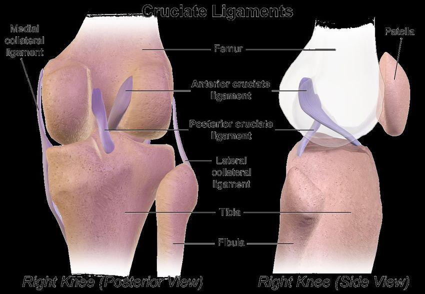
Ligament Cross Sections and Lengths based on Literature

 • Ligaments do not show well on scans, we used literature to
 reconstruct them

 ACL Ref 148: Harner, C., et al.,
 Quantitative Analysis of Human Cruciate
 Ligament Insertions. J. Arthrooscopic
 and Rel. Surg., 1999. 15(7): p. 741‐749.

 PCL Ref 148 and 151: Takahashi, Y., et al.,
 Development and Validation of the Finite
 Element Model for the
 Human Lower Limb of Pedestrians. Stapp
 Car Crash J, 2000. 44.

 C IB
Knee Articular Cartilage

 Fibula Cartilage
 Femur Cartilage

 Tibia Cartilage

 www.bartleby.com
 C IB
Femur Cartilage Tibia Cartilage Patella Cartilage

 Femur Cartilage Tibia Cartilage Patella Cartilage
 Measured Values --- medial Lateral ---
 Volume (mm^3) 13680 1988 1804 3487
 Avg Thickness (mm) 2.18 1.71 1.63 2.46

 Ref 1 Literature Values Average - Both Sides
 Thickness (mm) 2.14+/-0.53 2.38+/-0.90 3.08+/-0.94

 Ref 2 Literature Values medial Lateral
 Volume (mm^3) 15000+/-2600 1920+/-490 2550+/-510 3560+/-480
 Thickness (mm) 1.88+/-0.29 1.36+/-0.15 1.76+/-0.27 2.39+/-0.42

 Good thickness and volume agreement between CAD and Lit
 1 Cohen et al., Osteoarthritis and Cartilage, 1999; 2 Faber et al., Skeletal Radiol, 2001
 C IB
Tibial Plateau Cartilage vs. Literature

 CAD
 Literature 1, 2

 Medial
 Anterior

 Good match between CAD and
 Literature thickness distribution

 1 Zohara et al., J Osteoarthritis Res Soc Int, 1999; Raynauld et al., Osteoarthritis and Cartilage, 2003
 C IB
Femur Cartilage vs. Literature
 Proximal Literature 1

 Trochlea
 cartilage

 Condylar
 cartilage

 Lateral Condyle Medial Condyle

 Good match between CAD and
 Literature thickness distribution

 Posterior
 1 Zohara et al., J Osteoarthritis Res Soc Int, 1999
 C IB
Patellar Cartilage vs. Literature

 Literature 1

 Proximal

 Lateral

 Good match between CAD and
 Literature thickness distribution
 1 Zohara et al., J Osteoarthritis Res Soc Int, 1999
 C IB
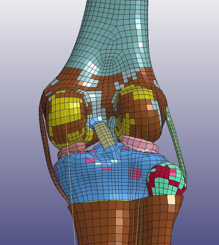
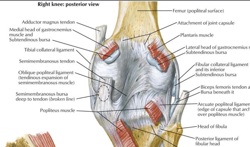
Diagram of the knee vs. the M50-PS
 Posterior View of Right Leg

 ACL

 PCL

 https://www.wikiwand.com/en/Cruciate_ligament
 C IB
Diagram of the knee vs. M50-PS
 Lateral View of Right Leg

 ACL

 PCL

 https://www.wikiwand.com/en/Cruciate_ligament
 C IB
Description of ACL from Gray’s Anatomy
 Superior Superior

 • “The ACL (Blue) is attached
 to the depression in front of
 Upward, backward travel of ACL
 the intercondyloid eminence Lateral travel of ACL

 of the tibia, being blended To: lateral
 with the anterior extremity of condyle of
 femur

 the lateral meniscus; it passes Post Ant.
 upward, backward, and lateral Lateral
 From: Front
 Medial of tibia
 ward, and is fixed into the
 medial and back part of the
 lateral condyle of the femur” Right knee of M50-PS v. 1.4.5
 https://www.bartleby.com/107/93.html Inferior Inferior

 C IB
Description of MCL from Gray’s Anatomy
 Superior Superior
 • The PCL (Red) is stronger, but
 shorter and less oblique in its
 direction, than the anterior. It is
 attached to the posterior Medial travel of PCL
 Upward, forward travel of PCL
 intercondyloid fossa of the tibia, To: medial
 and to the posterior extremity of condyle of
 femur
 the lateral meniscus; and passes Post Ant.
 upward, forward, and Lateral Medial
 From:
 medialward, to be fixed into the posterior
 tibia
 lateral and front part of the
 medial condyle of the femur.
 Right knee of M50-PS v. 1.4.5
 https://www.bartleby.com/107/93.html
 Inferior Inferior

 C IB
Knee Interior
 • The outer surface of the knee is
 not an anatomical capsule, rather
 the “knee interior 2D surface”
 • It was made for contact
 implementation for this
 simplified knee, this is rationale
 for including the patella
 • The detailed pedestrian model
 knee follows the knee anatomy

 C IB
GHBMC M50-PS AND –PS FAMILY IN
EURONCAP CERTIFICATION PROCESS

 C IB
Methods: Euro NCAP Setup
 Family Car (FCR) Multi-Purpose Vehicle (MPV)
 30 kph | 40 kph | 50 kph
 4 Vehicle Geometries
 12 simulations per HBM
 48 Total Simulations

 M50-PS Sensor Locations

 Head CG

 Roadster (RDS) Sport Utility Vehicle (SUV)

 T12

 Acetabulum

 Development of Generic Vehicles was completed under Coherent Project (Klug et al. 2017) C IB
Results: M50-P Certification
 • Pre – Post Simulation Check FCR 50 kph Corridors
 • 50th male certification
 – Kinematic response corridors Corridors created
 – Time of head impact (HIT) from response data
 – Force monitored for stability from 18 proposed
 HBMs for the study
 • All sizes to be simulated for HIT assessment
 Tolerance : 50 mm
 and stability
 • Other HBM size certification
 FCR 50 kph
 – All sizes to be simulated for HIT assessment
 and stability
 – Certification of 50th model size certifies

 HIT (ms)
 HIT tolerance interval
 other sizes of same model family HBM
 Mean Target
 of +3.5% and -7% of
 • 6 year old certification mean target
 Tolerance
 – To begin January 2020

 Decker et al. 2019, Traffic Inj Prev
 C IB
MODELING SUPPORT SLIDES

 C IB
Pedestrian Modelling

 1.GHBMC Pedestrian Model (PS- Simplified Version) -
 Overview
 2.GHBMC Model Validation
 3.GHBMC Knee Model – Component Validation
 4.GHBMC Knee Model – CTP Validation

 C IB
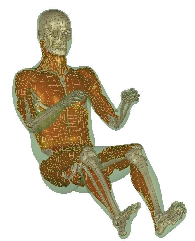
GHBMC 50th PS Model

 C IB
GHBMC Pedestrian Validations (1)
 1. Thigh Dynamic 3-Point Bending 2. Leg Dynamic 3-Point Bending 3. Pelvis Acetabulum Lateral Impact 4. Pelvis Iliac Wing Lateral Impact

 5. Lateral Shoulder Impact at 4.5 m/s 6. Lateral Shoulder Impact at 6.8 m/s 7. Lateral Pelvis Impact at 5.2 m/s 8. Lateral Pelvis Impact at 9.8 m/s

 9. Abdomen Impact 4.8 m/s 10. Abdomen Impact at 6.8 m/s 11. Abdomen Impact 9.4 m/s 12. Thorax Impact at 4.4 m/s

 13. Thorax Impact at 6.5 m/s 14. Thorax Impact at 9.5 m/s 15. 4 Point Knee Bending 16. Lateral Impact: Sedan 40km/hr

 C IB
GHBMC Pedestrian Validations (2)
 17. Lateral Impact: SUV 40km/hr 18. Lateral Impact: Van 40km/hr 19. Lumbar Spine Bending 20. Kerrigan lateral impact

 Sacrum

 Head T1

 21. Femur 3 Point Bending -Unloaded 22. Femur bending under 23. Femur Head Fracture In Stance and Fall 24. PCL Stretch Test
 Anterior/Posterior Loading

 The fracture locations and the fracture
 force companions of the proximal femur
 compression tests and FE simulations in
 both (a) stance and (b) fall configurations

 25. Dorsiflexion loading at 30ms 26. Foot rotation 27. Foot-Ankle-Leg Inversion/Eversion 28. Foot-Ankle-Leg Inversion/Eversion
 Loading Loading and Axial Loading

 29. Foot-Ankle-Leg Axial Impact 30. Mid Thigh Bending Test 31. Knee-Thigh-Hip Impact 32. Knee-Thigh Impact

 C IB
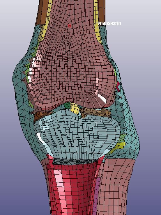
Validation: Lower extremities (knee joint)

 • Knee joint was loaded under valgus bending1

 • Extension beams rotated about 1 °/ms (approximately 40
 km/h impact velocity)

 • Bending moment vs degree was recorded at the load
 cell

 1 Bose et al. 2008

 C IB
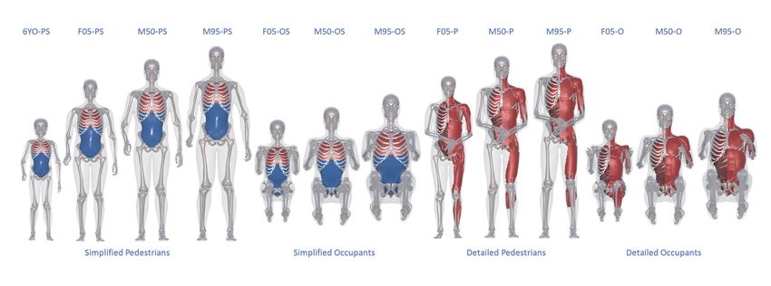
Knee FE Model
 The part Knee-Interior_2D is
 not designed to simulate the
 - knee capsule, but to globally
 represent multiple missing
 anatomical components
 (ligaments, tendons,
 capsule, synovial liquid) in
 the knee.

 The thickness and material (0.2 mm / 850 MPa) properties of this part are not
 relevant. They are just obtained from calibration and depend of the Boundary
 Conditions chosen for this part.

 C IB
Lower extremities (knee joint)
 • Similar trend as the curves corresponding to

 PMHS tests1

 • ACL and MCL were ruptured

 ➢ MCL (52.5 %), MCL+ACL (10 %)1

 MCL: Medial collateral ligament
 ACL: Anterior cruciate ligament

 C IB
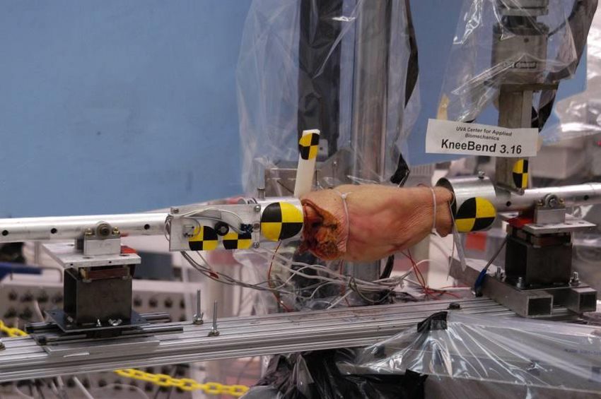
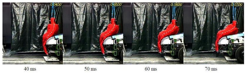
LAB PMHS Test Data

 40 km/h

 Experimental and simulation set-up1

 1 Song et al. 2017

 C IB
LAB PMHS Test Data

Whole-body validation setup with simplified generic vehicles; a) sedan (3), b) SUV (5) and c)
Van (3)

 C IB
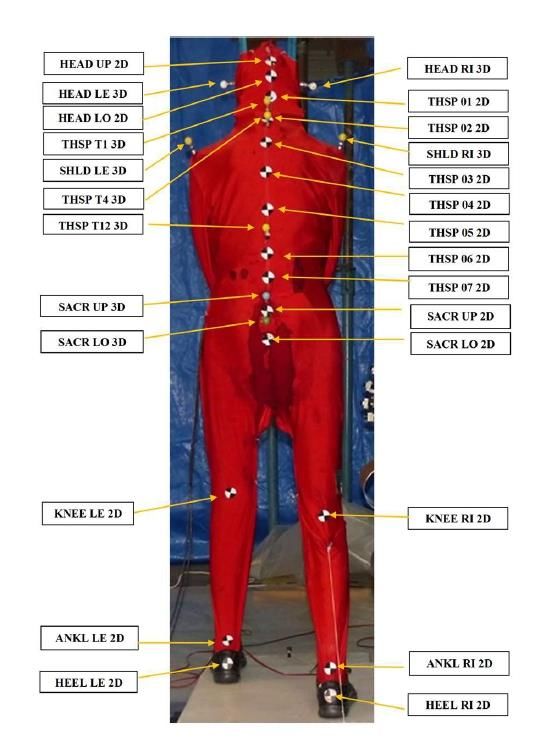
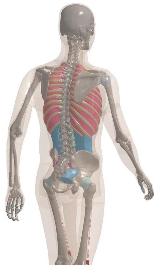
PMHS Knee Angle Update
 Goal: Calculate Knee Angle in PMHS tests using the Femur Head as a
 reference point rather than the bone surface of the Greater Trochanter

 Available Data:
 • Initial Coordinates
 • Skin surface of left & right Greater Trochanters (GT)
 • Continuous Coordinates
 • Two sacral points
 • Both Knees
 • Both Ankle
A: Femur Head Key Assumptions: Sacrum and femur head are effectively rigidly
B: Greater trochanter Bone
Surface connected, suggesting the distance between them doesn’t change

 Procedure:
 1. Estimate coordinates of femur head using PMHS hip width and dimensions from GHBMC
 M50P-v1.6 model
 2. “Track” femur head location using coordinates of sacrum
 C IB
Step 1. Estimate location of Femur Head

 t

1. Calculate the ratios ( , ) of outer hip diameter (d) to horizontal and vertical
 distance from the greater trochanter skin surface (t) to the tip of the femur head (f)
 using dimensions from the GHBMC M50P-v1.6 model.
 x −tx z − f
 = γx = 0.31 = γz = 0.10
 d
2. Estimate PMHS femur head initial coordinates (F) using the initial location of the
 greater trochanter skin surface (T) and hip width (D)

 = ∗ γx + = ∗ γz +

 C IB
Step 2. Track the Femur Head
 Reminder: PMHS testing records the location of two points on the sacrum

 1. Assume the sacrum and femur head are rigidly attached, meaning the
 length between the two sacral points and the femur head remains constant
 ( 1 , 2 )
 2. Plot a circle for both sacrum points moving through time, radius 1 or 2
 3. The intersection point of the circles is the femur head location

 Step 3. Calculate Knee Angle
 Reminder: PMHS testing continuously records the location of the knee
 and ankle

 1. Create vectors between the Ankle-Knee and Knee-Greater Trochanter
 2. Calculate knee angle using the dot product between the two vectors

 C IB
Step 3. Calculate Knee Angle

 Reminder: PMHS testing continuously records the
 location of the knee and ankle

 1. Create vectors between the Ankle-Knee and Knee-
 Greater Trochanter
 2. Calculate knee angle using the dot product between
 the two vectors

 C IB
Model validation – LAB tests/Coronal plane knee angle
 a) Sedan b) SUV c) Van

 C IB
Model validation – LAB tests/Kinematics
 Head T1 Knee
 Sedan
 SUV
 Van

 C IB
Conclusions
 • The development process of the GHBMC M50-PS knee used ad
 hoc scans from recruited subjects
 • There is high confidence in the placement of the knee bones
 and the gaps between bones for soft tissues, models are based
 on subject upright MRI data
 • The ligament placement is based on anatomical texts
 • The knee “capsule” in the simplified models was designed for
 contact control, and is not meant to be anatomically based
 • The simplified pedestrian models meet the EuroNCAP
 pedestrian protocol
 • Validation data were presented
 C IB
Acknowledgements

 • GHBMC and the FBM COE at Wake Forest and Virginia Tech
 would like to thank IWG-DPPS for and providing us with an
 opportunity to present today

 C IB
SUPPLEMENTAL

 C IB
Lower Extremity Cases
 • Thigh Model in Medial Side Impact (Kerrigan et al.
 2004)
 • Femoral Shaft Model in Bending Load (Funk et al.
 2004)
 • Femoral Shaft Model in Combined Loading
 (bending and compression) (Ivarsson et al. 2009)
 • Femoral Head Model in Compression Loading
 (Keyak et al. 1998)
 • PCL Model in Knee Shear Loading
 (Balasubramanian et al. 2004)
 • Tibial Shaft Bending in Lateral and Medial
 Direction
 • Limb Model in Knee-Thigh (KT) Impact (Rupp et al.
 2003)
 Regional Validation
 • Lower Limb in Knee-Thigh-Hip (KTH) Impact (Rupp Dr. Costin Untaroiu
 et al. 2002, 03) Dr. Jeff Crandall

 C IB
Foot ankle cases
 • Foof, Axial Impact Loading (Funk
 2000)
 • Foot, Dorsiflexion Loading (Rudd
 2004)
 • Foot, Xversion Loading (Funk
 2002)
 • Foot, Axial Impact with Achilles
 Tension (Funk 2000)
 • Foot, Combined loading (Funk Regional Validation
 Dr. Costin Untaroiu
 2002) Dr. Jeff Crandall

 C IB
You can also read