Selection of System at Planning Stage
        of Metro Rail Project
←
→
Page content transcription
If your browser does not render page correctly, please read the page content below
Selection of System at Planning Stage
of Metro Rail Project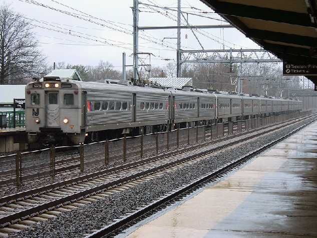
ALIGNMENT ROUTE MAP
CORRIDOR DETAILS
Route Details
         Name of Corridor                           Distance (In Km)
                                         Elevated      U/G             Total
East - West Corridor
                                         14.402        6.335       20.737
(Thaltej Gaam to Vastral Gaam)
North -South Corridor
                                         18.522          --        18.522
(APMC to Motera Stadium)
                                 Total   32.924        6.335       39.259

Station Details
         Name of Corridor                            No. of Stations
                                         Elevated        U/G            Total
East - West Corridor
                                            13                4           17
(Thaltej Gaam to Vastral Gaam)
North-South Corridor
                                            15                --          15
(APMC to Motera Stadium)
                                 Total      28                4           32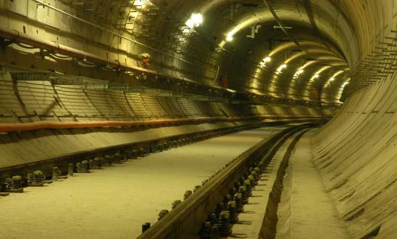
PROJECT COST DETAILS
     Name of Corridor          Distance   Estimated completion cost with
                               (In km)       central taxes & land cost
                                                    (INR Crore)
East - West Corridor
(Thaltej Gam to Vastral Gam)   20.737                 6681

North -South Corridor
( APMC to Motera Stadium)      18.522                 3994

Interest During Construction
                                                       98

            Total              39.259                 10773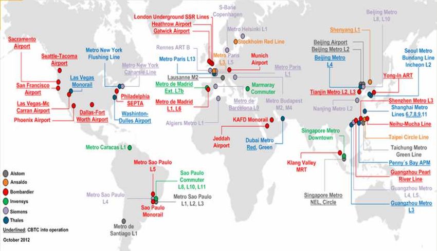
FINANCING OF THE PROJECT

         DETAILS                   AMOUNT (IN INR)

  EQUITY OF GOVT. OF INDIA              1990 CR.

EQUITY OF GOVT. OF GUJARAT              1990 CR.

      ODA/LOAN (JICA)                   6066 CR.

SUB-ORDINATE DEBT (SD) FROM             727 CR.
           GOG
             TOTAL PROJECT COST – 10,773 CR.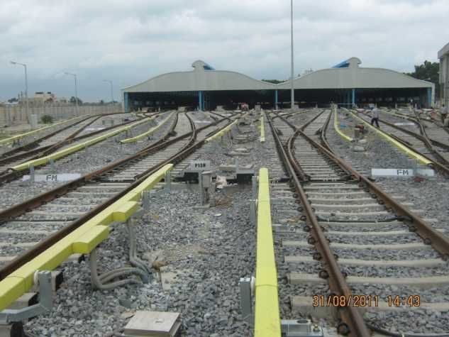
SYSTEM SELECTION
The following systems are mainly available for Urban Mass
  Transit:

High Capacity Metro    For high peak hour traffic densities exceeding
System                 40,000 PHPDT

Light Capacity Metro   For moderate peak hour traffic densities exceeding
System                 8000 PHPDT.

Light Rail Transit     Modern trams-Street Cars running on Rails at
                       grade or elevated with sharp curves of 24m radius.

Other Systems          • Maglev
                       • Linear Induction Motor (LIM) Train
                       • Monorail
                       • Bus Rapid Transit System
                       • Automated Guide way Transit System
Capacity of Various Modes
•   In their report on urban Transport of 12th five year Plan, the working group has
    set the guidelines for the choice of different modes are as follows:
    System                                  PHPDT in 2021
    Metro rail#                             >=15000 for at least 5km continuous
                                            length
    LRT primarily at grade                  =< 10,000
    Monorail@@                              =< 10,000
    Bus Rapid Transit System                >=4,000 and upto 20000
    Organized City Bus Service as per
    urban bus specifications
•   #for having Metrorail, the city should have a ridership of at least 1 million on
    organized public transport (any mode)
•   @@Monorail is desirable only as a feeder system or where the narrow roads

    are flanked on either side by high rise buildings. In monorail while the cost of
    construction, operation and maintenance is almost the same as elevated
    metro rail, the carrying capacity is much lesser.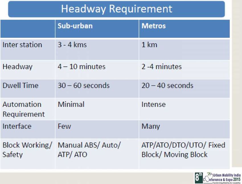
PHPDT Demand Projection of MEGA
                             PHPDT
Corridor/Year   2018      2021         2031         2043
North South     8476      12097        17778        26484
Corridor
East West       10593     15659        19251        22944
Corridor

   MEGA has adopted a stable, tested and reliable Metro
   technology i.e. Light Capacity Metro System to cater PHPDT
   of 15000 to 25000.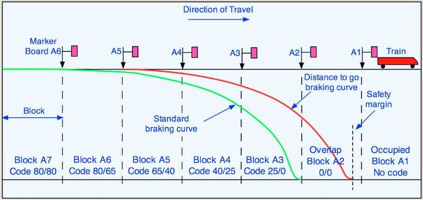
MAJOR SYSTEMS OF METRO RAIL
          PROJECT

•   ROLLING STOCK
•   SIGNALLING
•   TELECOMMUNICATION
•   TRACTION POWER
•   TRACK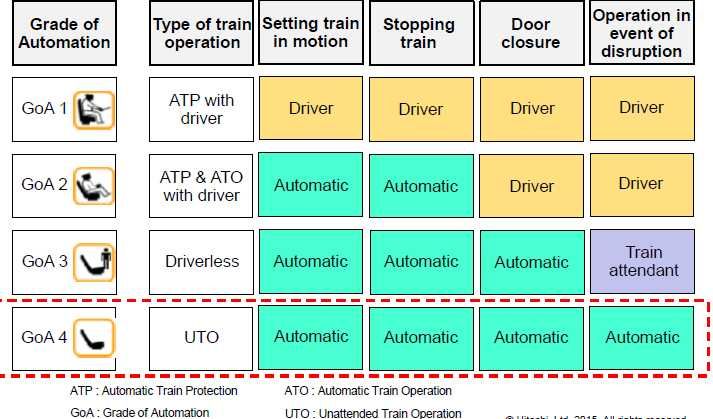
ROLLING STOCK
ROLLING STOCK

•   Level of automation in train operation
•   Propulsion
•   Bogies
•   Communication
•   TMS
•   Car body
•   Emergency evacuation system
•   Fire protection system in Metro train
•   Coupling Arrangement
Grade of Automation(GoA)
Level of automation in train operation
• Presently in India, GoA-2 is being followed.
• However we must aim for GoA-3 or GoA-4 level of
automation in future projects.
• Criteria's to be ensured while adopting GoA 3/GoA 4:
Very high reliability requirements
Redundancy for key functions
Management of possible failure scenarios
Reliable communication links
Simple interface with commuters
Build-up commuter confidence with appropriate information
Robust obstruction detection devicePropulsion • Brush less 3 phase induction motors • Speed is regulated by VVVF control • Regenerative braking by lowering the frequency and the voltage • DC voltage from the 3rd Rail is stepped up through a ‘STEP up Chopper which feeds Inverter operated with PWM control technology and using IGBT. • Percentage of Motorisation : 50% or 67% or 75%.
Bogies

      • Bolster less lightweight fabricated /Cast steel bogies with
        rubber springs are now universally adopted in metro cars.
      • Require less maintenance
      • Overhaul interval is also of the order of 4,20,000km
      • Use of air spring at secondary stage to keep floor level constant
        irrespective of passenger loading
Motor Bogie

Trailer Bogie
Communication • Two way communication between OCC and train driver. • Cab to Cab communication. • Emergency Intercom between Passenger & Train Driver. • Chime when doors are closing and opening.
PASSENGER INFORMATION AND PASSENGER SALOON
                 SURVEILLANCE SYSTEM

• Passenger Information System.
  • Automatic Digital Voice Announcement and Public Address
    System.
  • Broadcasting of Pre-recorded announcement through digital
    voice announcement system.
  • LCD/TFT based Electronic Information Display (EID).
  • Electronic Destination Display (EDD).

• Passenger saloon surveillance system based on IP Cameras,
  Network Video Recorder (NVR), CCTV.
Block Diagram of CCTV System
Train Management System(TMS)
TMS Features:
TMS is a microprocessor based systems
used for the automatic monitoring and
display , control and fault reporting and
recording of the subsystems on the train
through the Train bus (ARCNET) and Local
bus (RS-485).
The main on-board devices are constantly
monitored, and any failures are recorded
and notify the driver in real time mode.
Video Display Unit This supports fast and accurate corrective
of TMS measures to be taken when fault or
emergency situations occur, and helps to
promptly identify the cause of failure.Car body • Stainless steel / Aluminium car bodies. • No corrosion repair. • Energy saving due to its lightweight. • Cost saving due to easy maintenance and reduction of repair cost. • Riding comfort and safety in case of a crash or fire
Emergency Evacuation System

• Side Evacuation Vs. Front Evacuation
• Four doors on each side of the coach.
• Two emergency ramps per car with storage box under the
  saloon seat.

                                    Locations of each emergency ramp
Fire Protection system • Provided with fire retarding materials having – low fire load – low heat release rate – low smoke • Low smoke zero halogen type cables used which ensures passenger safety in case of fire. • One no. of Portable fire extinguisher in cab and two no. in each car . • External Fire/smoke detector in cab HVAC .
Coupling Arrangement
3 car train
DMC TC DMC
Cab End Automatic Coupler Semi-permanent Coupler
Location: Cab End Semi-permanent Coupler
Automatic coupler with with Pneumatic connection
Pneumatic connection with or Energy absorption device
without Electric connection
Energy absorption deviceCoupling Arrangement Conversion to 6 car arrangement in future Option-1 DMC TC DMC DMC TC DMC • Two 3 car trains can be coupled directly. Option-2 DMC TC MC MC TC DMC • Special arrangement is required and can not be used separately.
SIGNALING AND TRAIN CONTROL
          SYSTEMS
Signaling and Train Control Systems • Primary task : Safe and efficient movement of trains • Reliable train detection – using Track circuits/Axle counter (DTG signaling) OR Radio Beacon (CBTC) • Interlocking for Points/Signals control (wherever provided) • ATP / ATO – Efficient and error free train operations • ATS: Automation of operations, interfaces, sub- systems
DISTANCE TO GO SIGNALING – Currently being used in Indian
Metros
CBTC SIGNALING – Definition
CBTC SIGNALING

Communication Based Train Control (CBTC) systems based
on moving block allows the reduction of the safety
distance between two consecutive trains. This distance is
varying according to the continuous updates of the train
location and speed, maintaining the safety requirements.
This results in a reduced headway between consecutive
trains and an increased transport capacity.
DTG and CBTC Performances

                 Distance to Go to CBTC Moving Block

DISTANCE TO   40                                               Braking Curve for Distance to Go
GO

                                                         Stopping
                                                         Point
   Authorized
   Speed
   Track Detection         Track Detection                     Track Detection

CBTC MOVING             Braking Curve in Moving                    Protection Envelop
BLOCK       40          Block                            Limit of          Stopping
                                                         authority         Point

                                                  Gain in Moving
                                                  Block
                                                  [Radio Free
                                                  Propagation]
Worldwide CBTC Installations
Why to have CBTC Signaling solution?
• Almost 99.99% availability means 10mts of downtime in a year.
• Maximised energy savings and optimised maintenance
through accurate train simulation
• Reduced headways possible as compared to DTG.
• Matured technology now and Supports UTO operations (GoA4) –
DTG technology slowly getting obsolete.
• Centralized ATS can control the entire lines , no local ATS.
• Backup can be provided using Interlockings and wayside signals for
Crossing Stations
• Redundancy within the system:
Interlocking and wayside systems
Data communication systems
On-board equipments
CBTC radio links and systems
ATS,
BCC as backup to OCCWhy to have CBTC Signaling solution?
• Optimal driving performance for all train types
• Highest safety standards for all operating procedures
• Fast recovery of train operations after disruption due to equipment
• As more functions are managed by the central redundant servers:
• Less Equipment are needed – even line-side signals can be
dispensed with.
• Less Power is required
• Less Space is needed in the technical rooms
• Less Maintenance
• Less capital and life cycle Cost
• Scalable systems for future expansionsSignaling System Requirements - Planning • Traffic requirements and forecast for future • Headway requirements • Grade of Automation required • Availability of trained personnel for operations and maintenance • Mean time between Failures (MTBF) • Mean time to rectification (MTTR) • Technology obsolescence
TELECOMMUNICATION SYSTEM
REQUIREMENTS OF TELECOM SYSTEMS IN METROS

• For Efficient O&M, essential to have an organized Telecom
  system network covering strategic locations – OCC, Stations,
  Depots etc. Also reliable links between train and
  OCC/Stations/Staff
• Telecom system provides necessary channels for
  voice/data/video signals for management and operations
  including security.
• Control and supervision of the sensitive AFC systems
• Data system requirement for Rolling stock interface to
  OCC/Depots
• Communication requirements for SCADA and Signaling/Track
  /Traction/Rolling Stock Fault controls
Telecom Infrastructure Features
• Proven solution on equivalent operational
  networks
• World Class level
• Standard-based and open architecture
• No Single Point of Failure
• Reliable, redundant, scalable and cost-
  effective
• Guaranteed and Secured infrastructure
• Easy to operate and maintain
• Integrated solution
TELECOM SUB SYSTEMS
• FIBER OPTIC BACKBONE SYSTEM
• USE OF IP BASED TECHNOLOGY IN PLACE OF OBSOLETE SDH
  SYSTEMS
• NETWORK MANGEMENT SYSTEMS
• TETRA RADIO SYSTEM FOR TRAIN TO STATION/OCC
  COMMUNICATIONS
• TELEPHONE SYSTEMS
• PA SYSTEMS
• PIDS SYSTEMS
• CCTV SYSTEMS FOR SURVEILLANCE
• MASTER CLOCK AND STATION CLOCKS WORKING ON IP
• ACCESS CONTROL AND INTRUSION DETECTION SYSTEM
• CENTRALISED DIGITAL RECORDING SYSTEM
Telecommunication system - Solution Architecture
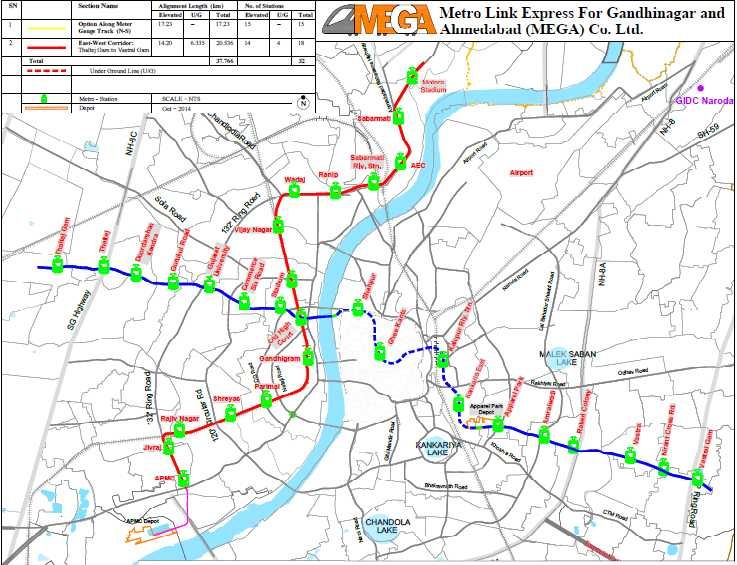
Integrated Control Centre - Architecture Principle
                                                                                                                                                                   Control Center

                                                            INTEGRATED CONTROL SECURITY & PASSENGER INFORMATION CENTER

UNIFIED HUMAN
   MACHINE
INTERFACE (HMI)

                     Map View                         Traffic Control           PIS Manager               CCTV Manager                 SCADA                      Ventilation

   SERVERS
                                Traffic Supervision                                      Security                                      Auxiliaries                     Power
                                        ATS                                           CCTV, PA / PIS                                    SCADA                         SCADA

COMMUNICATIONS

  SUBSYSTEM       Trackside            Interlocking             Train Control   Security CCTV            Passenger        Electro                Access Control         Power
  EQUIPMENT                                                                                             Information      mechanical

                                                                                                       Fire Detection    Ventilation             Fire Detection
TRACTION POWER SYSTEM
Traction Power System
• Selection of traction power system is based on economics of
  energy supplies, maintenance and capital cost. Different
  systems are used for urban and inter city areas.

• Electrification system can be classified by following main
  parameters:

    Voltage                750V DC, 1500V DC or 25kV AC
    Traction Current       AC or DC
    Current Collection     Overhead or Third Rail
    system
    Control                Local or Remote
Direct Current system
• Large speed range can be achieved by VVVF control.
• Generally operates on a voltage below 1 KV for safety reason.
• Relatively low DC voltage that the motors can use directly.
• To minimize resistive losses, it requires:
– thick & short supply cables/wires
– closely spaced converter stations.
• Limit over distance between feeder stationsThird Rail Current Collection • More compact. • Better to be used for smaller-diameter tunnels. • Prone to losses due to limit of voltage upto 1200 V. • The use of AC is not feasible for third rail. • Third rail systems can be designed to use top contact, side contact or bottom contact. • Limited to relatively low voltages, limiting the size and speed of trains. • Less Visual Pollution as compared to OCS.
Overhead Current Collection
• Uses higher voltages for efficiency consideration.
• Smaller energy loss.
• Economical system .
• Drawbacks:
   – Phases loaded unequally
   – Significant EMI generated
• Special structure needs to be constructed for overhead line.
• Special provision to be made where there is a overhead cross-over
  in urban areas and for tunnel entry.
OVERHEAD CURRENT COLLECTION
THIRD RAIL CURRENT COLLECTION
THIRD RAIL CURRENT COLLECTION
Regen Energy Recovery System (for DC third rail systems)

•   To feed back the regenerative brake energy back to supply system.
•   An advanced substation for networks from 600V DC to 1500V DC
•   Best energy efficiency with 99% of braking energy recovery & high energy quality
•   Reduced infrastructure
MEGA’s Choice for Traction Power System

• MEGA has considered 750 V DC third rail system for the
  project due to the following reasons.
   – No visual intrusion in City Skyline.
   – OHE is more failure prone due to Kite flying in Ahmedabad.
   – No electromagnetic interference.
   – Less clearance is required in tunnels and passing under
     bridges.
   – To overcome the possibility of electrocution to daily
     commuters, MEGA is proposing PSDs in station areas.
TRACK
TRACK SYSTEM

• TYPES OF TRACK SYSTEM
  – BALLASTED
  – BALLASTLESS
BENEFIT OF BALLASTLESS TRACK OVER CONVENTIONAL
BALLASTED TRACK
REDUCTION OF STRUCTURE HEIGHT
HIGHER AVAILABLITY FOR OPERATION
HIGH LATERAL TRACK RESISTANCE
LESS MAINTENANCE
GOOD SUPPORT AND LONG SERVICE LIFE
VIBRATION ATTENUATION (IN TUNNEL ONLY)
LOW DEAD LOAD (VIADUCT ONLY)
EASE OF CONSTRUCTIONBENEFIT OF CONVENTIONAL BALLASTED TRACK OVER
BALLASTLESS TRACK
RELATIVELY LOW CONSTRUTUION COST
HIGH ELASTICITY
HIGH MAINTAINALIBITY AT RELATIVELY LOW COST
HIGH NOISE ABSORPTION
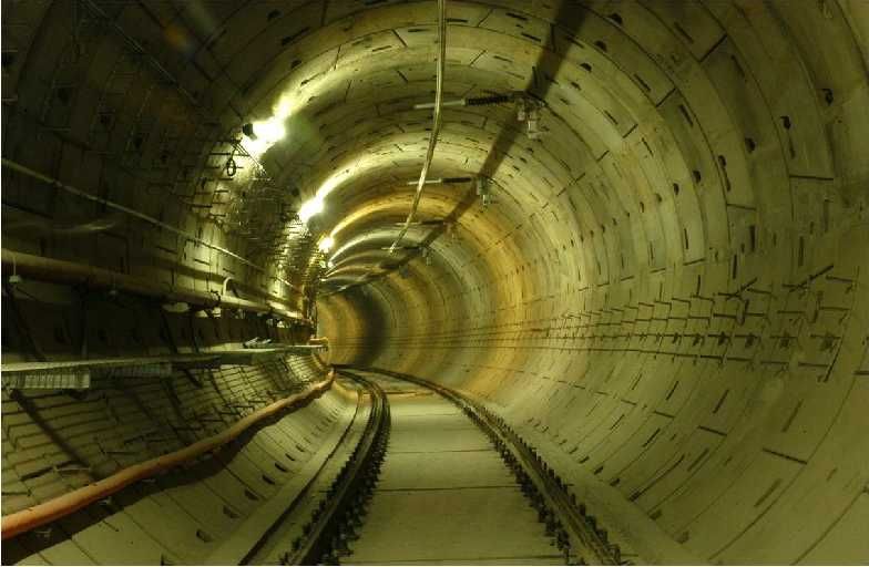
EASE OF CONSTRUCTIONTrack System Choice • MEGA has adopted ballastless track on viaducts & tunnels. • However, in depot yard area, ballasted track will be adopted.
Base-plated Ballastless track in tunnel
Thank You
You can also read