User Guide EMA Manager - APsystems USA
←
→
Page content transcription
If your browser does not render page correctly, please read the page content below
User Guide
                                                  EMA Manager
                                                  Rev 1.0.0 03/15

APsystems
1 Yatai Road, Jiaxing 314050, China
TEL: +86 -573-83986967 info@altenergy-power.com
www.APsystems.com

© All Rights Reserved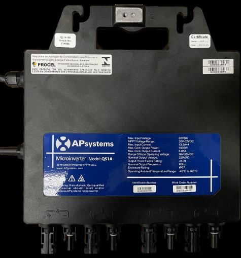
Table of Contents
1.   Introduction ........................................................................................................................... 3
2.   Install and Login EMA Manager ............................................................................................... 3
3.   Home (Installer Level) ............................................................................................................. 5
4.   User (Installer Level) ............................................................................................................... 8
      4.1 Home (End User Level) ................................................................................................ 12
      4.2 Module (End User Level) ............................................................................................. 13
      4.3 Data (End User Level) .................................................................................................. 14
      4.4 Workspace (End User Level) ........................................................................................ 14
5.   Workspace (Installer Level) ................................................................................................... 16
      5.1 User Management (Installer Level) ............................................................................. 17
           5.1.1 Adding a New User Installation ......................................................................... 17
           5.1.2 Adding a New Share User Installation................................................................ 41
           5.1.3 Resume an Incomplete Registration .................................................................. 44
      5.2 Installer Management (Installer Level) ........................................................................ 47
           5.2.1 Adding a New Module ...................................................................................... 47
      5.3 Remote Control– ECU Management (Installer Level) ................................................... 49
           5.3.1 Manage Inverter UIDs ....................................................................................... 52
6.   Local Control (ECU APP) ........................................................................................................ 54
      6.1 Home (ECU APP) ......................................................................................................... 56
      6.2 Module (ECU APP) ...................................................................................................... 57
      6.3 Data (ECU APP) ........................................................................................................... 58
      6.4 Workspace (ECU APP) ................................................................................................. 60
           6.4.1 ID Management ................................................................................................ 61
           6.4.2 Grid Profile ....................................................................................................... 63
           6.4.3 Inverter Connection Progress ............................................................................ 64
           6.4.4 ECU Network Settings ....................................................................................... 65
           6.4.5 ECU AP Settings ................................................................................................ 67
           6.4.6 ECU Data Settings ............................................................................................. 68
           6.4.7 Meter Settings .................................................................................................. 69
           6.4.8 Automatic System Check ................................................................................... 73
7.   Do-It-Yourself Registration (ECU APP) ................................................................................... 74
8.   Manage Your Own Information (Installer Level) .................................................................... 76
      8.1 Modify Account Information (Installer Level) .............................................................. 77
      8.2 Reset Password (Installer Level) .................................................................................. 78
      8.3 Modify Company Information (Installer Level) ............................................................ 79
      8.4 Change APP’s Language (Installer Level) ...................................................................... 80

                                                                                                                                             2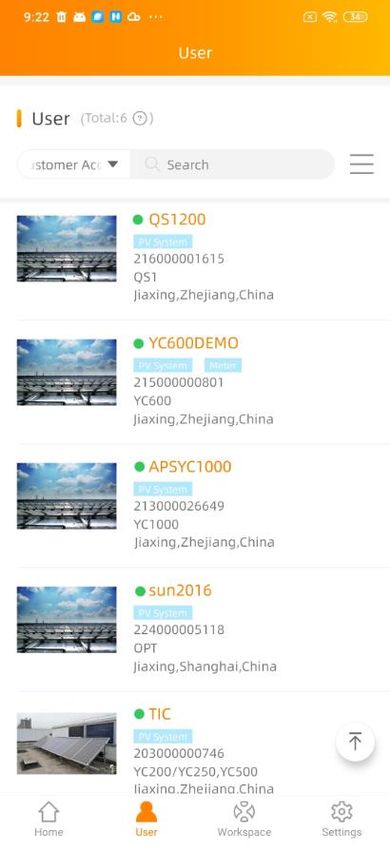
1. Introduction
EMA Manager is a one-stop application specially made for APsystems registered professional solar installers.
The content of the EMA Manager is the APP version of features available in installer account via the web
portal.
The EMA Manager APP will allow installers, to register end-users, new PV systems, to monitor performance
and ensure easy access to all key data without having to log into their laptop.
2. Install and Login EMA Manager
Install
Method 1:
1. Go to Google Play Store or Apple Store
2. Search “EMA Manager”
3. Download and install
Method2:
1. Open https://apsystems.com
2. Select your region
3. Click the tab menu “Apps” below “Products”
4. Download and install
Method3:
1. Open https://www.apsystemsema.com
2. Scan the QR code for Android or IOS
3. Download and install
Login
1. Enter your “Username” and “Password”.
Note: Use installer account Username and Password. The Password is case sensitive.
2. Press the “Login” button.
3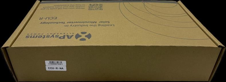
On the home page, a dashboard of your installed portfolio is displayed

Note: If no installation is registered, the dashboard will be empty.

Note: if you need to switch the language, click the “English” at the upper right corner and select language of
your choice

                                                                                                                 4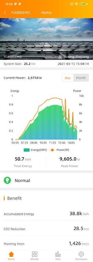
3. Home (Installer Level)

On the home page, installer can visualize
    - User: Total number of installations
    - Device: Total number and type of micros or ECUs installed
    - Energy: cumulative energy produced by the installed portfolio

On the home page, data are shown per year, but you have also access to prior day performance (yesterday)

Note: Installers with a network of sub-installers can also access to the details of their sub-installers. But they
are not permitted to view the operations and productions directly belonging to their sub-installers for the
data security and privacy.

By pressing “more” for each category, there is more granular data available:
    - Per quarter
    - Per system size

                                                                                                                     5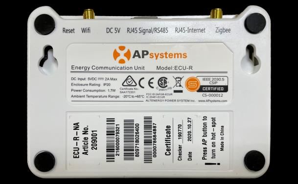
More

       6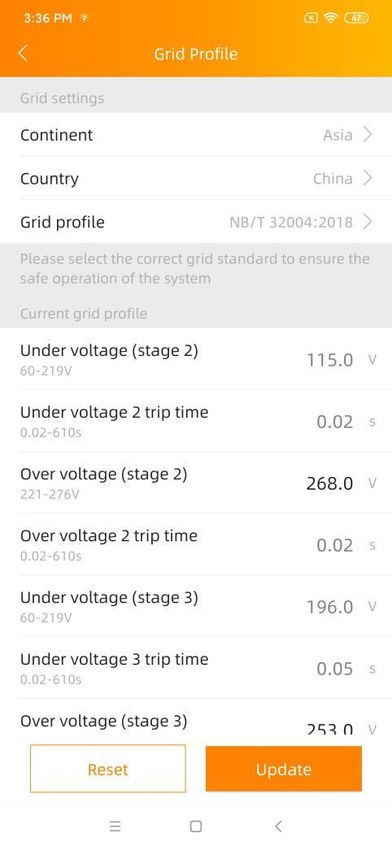
More

The “more” information shown above are also available via menu below “Report” in [Workspace].
    - Operation: View more granular data of user and device.
    - Production: View more granular data of production.

                                                                                                7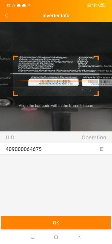
4. User (Installer Level)

You can view the detailed production of a single user the same as it shown in EMA APP to the users.

1. Once logged-in, Select the tab menu [User] at the bottom of the page.

A list of users is displayed.

                                                                                                      8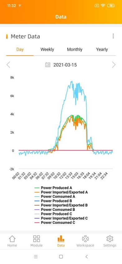
Note: A list of your sub-installers can also be displayed if you are a Master installer.
2. Select the user.
There are multiple selections for you to quickly search.
User List
Click the icon at the right side of the search field, the multiple choice of selections is displayed.
9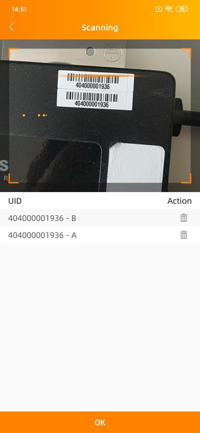
Display
You can select the fields you want to display in the user list.

Filter
You can also filter the user system with system running status and system type.

                                                                                  10
Green: The system is functioning normally
Yellow: Some micro-inverters communications has been interrupted since beginning of day or the micros
have not been properly registered (wrong UID, typo in the UID)
Red: ECU has been disconnected from the internet (power outage, change of router, change of wifi password,
wear and tear of the Ethernet cable, loose wifi antenna)
Grey: The system has never reported data (ECU might be connected to the internet, but the micros have not
been synchronized in the ECU during commissioning)
Share ECU User: Multiple customers’ PV system can be monitored via a single ECU using ECU Share mode. We
call these user “Share ECU User”.
ECU-C (Meter Activated): The system is using an ECU-C, with metering functions activated and CTs (current
transformers) in place.
Sort
You can select one field to sort the list.
Reset
Click it to reset the query conditions into default settings.
114.1 Home (End User Level)
In this view, you can view the registrations and productions of the user’s system with the running status.
124.2 Module (End User Level)
In this view, you can view each panel’s power in the whole day or daily energy in 30 days.
By using the sliding bar, the data will be automatically shown as per time of day
134.3 Data (End User Level)
In this page, you can view the detailed data on ECU level and inverter level:
- Per day
- Per month
- Per year
Switch Data Type
Note: If the system is using an ECU-C, with metering functions activated and CTs (current transformers) in
place, you can also visualize PV production, house-hold consumption and grid import/export data on meter
level.
4.4 Workspace (End User Level)
In this view, the name of the end-user is visible on the top left hand-side of the header.
In this View, you can manage the chosen user’s registration information, change the user’s security
information, replace the devices and configure the system remotely.
Note: This is specific to one single end user.
14Delete Current User
Account Details
- Personal information: Edit the end user’s personal information.
- ECU: Add/Edit/Delete ECUs.
- Inverter: Add/Edit/Delete inverters.
- Group View: Add/Edit/Delete group views.
- Upload picture: Upload/Delete pictures.
Account Security
- Reset password: Send the reset password email to the end-user.
The end-user will receive a link at his registered email address. By pressing this link, he will be able to
reset his password.
- Reset username: Apply a new username.
The end-user will be informed of the new username by an email after the new username is agreed.
Replace Device
- ECU-replace: Replace the ECU device.
- Inverter-replace: Replace the inverter device.
15 Remote Control
- ECU-remote: Manage Inverter UIDs in ECU, Set Grid Profile to ECU
Works only if the ECU is connected to the internet.
Note: Click “Delete” at the upper right corner of the page to delete this user.
5. Workspace (Installer Level)
In this View, you can manage the user’s registration information and installer’s registration information,
configure the system remotely and get granular data of multiple reports.
Note: This is a specific to all end users.
1. Once logged-in, Select the tab menu [Workspace] at the bottom of the page.
A list of functions is displayed.
Enter ECU APP
16 User Management
- Add User: Add a new user installation.
- Add Share User: Add a new share ECU user installation.
- Incomplete User: Resume the registration in case you were interrupted in any of the registration
steps.
Installer Management
- Module: Manage your module template or for your sub-installers.
Remote Control
- ECU-remote: Manage Inverter UIDs in ECU, Set Grid Profile to ECU
Works only if the ECU is connected to the internet.
Report
- Operation: View the statistics data of user and device.
- Production: View the statistics data of production.
Note: You can enter “Local Control (ECU APP)” without logout, switch your smart phone or tablet to connect
to ECU local Wi-Fi and click the “ECU APP” at the upper right corner. For more details, view “6. Local Control
(ECU APP)”.
5.1 User Management (Installer Level)
Introduction of the two different users.
User: Single end-user with one or multiple ECUs
Share User: Share-user is specific to the use of an ECU-Share: 1 ECU to monitor several installations with a
generic view for the installer and separated view for each user (typical use case: Social Housing)
5.1.1 Adding a New User Installation
There are five (5) major steps involved in adding a new installation (registering) in the EMA Manager. All the
following introductions take the customer as an example.
Step 1: Personal Information-Entering the customer’s personal information.
Step 2: ECU Information - Configuring the Energy Communication Unit (ECU).
Step 3: Inverter Information - Configuring the Inverter Information.
Step 4: Group View Information - Configuring the Group View.
Step 5: Upload Pictures (optional) - System Picture and/or Drawing Picture
17Add User
1. Select the “Add User” icon.
Start to add a new end user account.
Step 1: Entering the Customer’s Personal Information
2. Click “Add Personal Information”.
18The New User page is displayed. It divides personal information into “Account Info” and “System Info”. Fill in
the customer details by field; make sure including all required information.
19 Account Info
Username This is a single “name” (typically the customer’s last name) that identifies this specific
customer’s installation. The username appears in the customer’s area on the EMA.
(Required)
Only “letters”, “numeric digits”, “underscores”, “@”, “spaces”, and “.” Can be used
when creating a username. And the username is not case sensitive.
20Note: A username cannot be modified, once you submit the PERSONAL INFO. If your
customer wants to modify the username, you can submit the username modification
application after finish account registration. For details, please refer to “4.4
Workspace (End User Level)”.
Password This is a temporary password that is emailed to your customer so they can access
their account on the EMA. Your customer can change their password should they so
choose. (Required)
The set password must contain letters and numbers .
First Name Your customer’s first name. (Required)
Last Name Your customer’s last name. (Optional)
Email This is your customer’s email address. (Required)
Phone Number Your customer’s phone number. (Optional)
Allow visitors to Your customer can share his system on other website. (Optional)
Access to this system
Note: If enabled, it will display an authorization code to be used in embedding this
specific customer’s system on other website.
System Info
Installer This field is automatically generated by the system and can be changed using the
pull-down selector if necessary. (Required)
Country This field is automatically generated by the system and can be changed using the
pull-down selector if necessary. (Required)
State/Province This field is automatically generated by the system and can be changed using the
pull-down selector if necessary. (Required)
City Customer’s city. (Required)
Address Customer’s street address. (Optional)
Postal Code Customer’s postal code. (Optional)
21System Size Customer’s overall system size. (Required)
Module Type Customer’s solar panel type. (Required)
Module Maximum The maximum power of customer’s solar panel. (Required)
Power(Pmax)
Grid Type Grid environment where the system is connected to the grid (Required)
Remarks Add any notes that you may find useful at a later date. (Optional)
3. Click “OK”.
Note: Once you have clicked “OK” button in any of the major registration steps (1-5), your customer’s
information is saved in the system and you can step away from the process and resume by selecting
“Incomplete User” (Refer to 5.1.3 Resume an Incomplete Registration).
Step 2: Configure the Energy Communication Unit (ECU)
4. Click “Add ECU”
The Add ECU window is displayed.
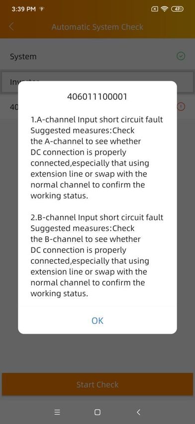
225. Enter the 12-digit ECU UID number(s) into the ECU ID field.
The ECU UID is located on the back of the ECU, as well as on the front flap of the shipping box.
The ECU UID is a unique APsystems “serial number” that is assigned to the ECU during manufacturing. It is
NOT the IP Address of the device.
It is critical that you enter the ECU UID correctly because the EMA uses this number to identify the system to
ensure monitoring and reporting.
236. Click “OK”.
Once you have entered all of the ECU UID numbers to be installed at a specific location, go to step 3.
Step 3: Configuring the Inverter Information
Note: In order to improve the registration efficiency, you can skip this step and register inverters by scanning
UIDs in step 4 “Configure the Group View” directly.
7. Click “Add Inverter”
The Inverter Information page is displayed.
In this step you are assigning the inverters to their associated ECU(s).
8. Select the ECU (ECU Selection field).
9. Select the “Add method”.
There are three methods for adding inverters into EMA.
24Note: Each inverter has a unique 12 digits UID which is located on the front of the inverter, as well as on the
back flap of the inverter’s shipping box.
Add Method 1: Import from ECU (Recommend)
A. Select “Import from ECU” in [Add Method]
B. Click “OK”
25This method can only be used when the ECU has been already commissioned on site (using the ECU_APP) and
connected to the internet. (please see ECU Quick Install Guide for more info)
Note: This list can be edited if necessary by selecting either “Edit” for each inverter and its associated channel.
Add Method 2: Input
A. Select “Input” in [Add Method]
B. Select “Type”.
26Note: You’ll be presented with a number of inverter types. Select the type you are installing, remembering
that the QS1, QS1A and YC1000 has up to four (4) channels (1, 2, 3 & 4), the YC600 has two (2) channels (1&2).
C. Input the UIDs in the input box.
Note: Only UIDs matching the selected type can be added. If you select micro type “YC600” but enter UID of a
QS1 “80x-”, an error message will be displayed.
D. Click “OK”
Add Method 3: Scan
A. Select “Scan” in [Add Method]
B. Select “Type”
27Note: You’ll be presented with a number of inverter types. Select the type you are installing, remembering
that the QS1, QS1A and YC1000 has up to four (4) channels (1, 2, 3 & 4), the YC600 has two (2) channels (1&2).
C. Click “Next”
The scanning page is displayed.
28D. Scan the UID bar code.
Note: Only UIDs with the same type selected before can be scanned.
E. Click “OK”
29Step 4: Configuring the Group View
This step will allow you to create the layout of the PV system.
11. Click “Add Group View”
The Create View page is displayed.
In this step you will fill in the basic view information.
12. Click “Next”
The panel layout page is displayed.
30There are 2 modes to display the layout details: Module mode or list mode.
Module Mode: Show the module position details in one page
List Mode: Show the inverter UIDs with the position in a list format
31There are 6 shortcut buttons to help you simplify the view registration.
- Search: Search UID.
- Clear UID: Delete UID located on the selected module.
- Clear all UIDs in current row: Delete all the UIDs located in the selected row
32- Clear all UIDs in current column: Delete all the UIDs located in the selected column
- Add row: Add a new row of empty modules to the bottom of the view.
- Add Column: Add a new column of empty modules to the far right of the view.
There are 3 methods for adding views into EMA.
Method 1: Distribute (Recommend)
UIDs with the position
A. Select the UID for the position
Note: When distribute the UIDs with the position, make sure you have registered the UIDs in step 3
(configuring the inverters information, see page 24), or you have entered all of the UIDs into the ECU, and
that ECU is correctly connected to the internet so that the APsystems server can retrieve the UIDs.
B. Click “OK”
Method 2: Input
A. Click “Add Button” and choose “Input”
The input page is displayed.
33Input Field
Input the UIDs in input field, the channel will be auto filled after you entered the UID.
B. Click “Complete Input” after finishing inputting
34C. Click “Ok”
Method 3: Scan
A. Click “Add Button” and choose “Scan”
The scan page is displayed.
35Add button
Scan the UID bar code to collect the UIDs. Please register the modules in accurate position according to the
installations on the job.
36Auto Next
Note: Turn on “Auto Next”, the next empty panel will be automatically selected in horizontal sequence when
scanning. Or else you need to choose the next panel.
B. Click “Finish Scanning”
C. Click “OK”
Note: The inverter ID can be registered as well even if it hasn’t been registered in Step 3 “Configuring the
inverter information” (see page 24]
3713. Click “Complete Registration”
If your customer does not have installation drawings or photo to upload, the registration is complete.
Step 5: Uploading the System Picture and/or Drawing Picture (optional)
14. Click “Upload Picture”
The upload picture page is displayed.
38Add button
The System Picture is displayed on the customer’s Dashboard and the installation drawings are displayed on
the customer’s Module Performance page.
Following formats are supported:
.jpeg
.jpg
.png
.pdf
15. Click “Add”
Choose the installation drawing or photo you want to upload. Make sure you have authorized the EMA
Manager APP to access to the pictures stored in your smart phone or tablet.
39Back button
16. Once the pictures or drawings have been uploaded, Click “Back” and then “Complete Registration”.
405.1.2 Adding a New Share User Installation
Multiple customers’ PV system can be monitored via a single ECU using ECU Share mode.
The “master” of ECU Share can see all sub-systems, while every owner of a sub-system can only see its own.
Require: First: register “Share ECU Master User”, then: register “Share ECU Sub User”.
Master User
Manage all of the micros connected to the same ECU
Sub User
Monitor their own system only
Note: In order to register sub-user via ECU Share mode, you need to have the “ECU Share” function enabled
on your installer account. Please contact your local APsystems Technical Support to have this feature
activated.
Add Share User
1. Select the “Add Share User” icon.
41Start to add a new share user account.
Adding Share ECU Master User
There are five (5) major steps involved in adding a new Share ECU Master User (registering) in the EMA
Manager. They are the same as the ones used to add a new user (For details, please refer to “Adding a New
User Installation”).
Step 1: Personal Information - Entering the customer’s personal information.
Step 2: ECU Information - Configuring the Energy Communication Unit (ECU).
Step 3: Inverter Information - Configuring the Inverter Information.
Step 4: Group View Information - Configuring the Group View.
Step 5: Upload Pictures (optional) - System Picture and/or Drawing Picture
42Adding Share ECU Sub User
Add Share ECU First
There are four (4) major steps involved in adding a new Share ECU Sub User in the EMA Manager.
Step 1: ECU Information - Configuring the Energy Communication Unit (ECU).
Note: When add new share ECU sub user, you need to add the share ECU first.
43Step 2: Personal Information - Entering the customer’s personal information.
Step 3: Group View Information - Configuring the Group View.
Note: In this step, you are only permitted to arrange the inverters.
Step 4: Upload Pictures (optional) - System Picture and/or Drawing Picture.
5.1.3 Resume an Incomplete Registration
In case you were interrupted in any of the registration steps (1-5), your customer’s information is saved in the
system. You can resume the registration by selecting “Incomplete User” under “User Management”.
44Incomplete User
1. Select the “Incomplete User” icon.
A list of your incomplete user registrations is displayed.
452. Select the customer account you want to complete.
3. Continue where you left off following the steps in the previous section. Refer to [5.1.1 Adding a New
User Installation] or [5.1.2 Adding a New Share User Installation].
465.2 Installer Management (Installer Level)
5.2.1 Adding a New Module
You can manage your module template or for your sub-installers.
The module template could be used to distinguish the module type installed at end-user.
Module
1. Select the “Module” icon.
A list of module templates is displayed.
47Add button
2. Click “Add” at the bottom right of the list.
The New Module page is displayed. Fill in the module details by field, make sure to include all required
information.
Note: You can select a module to modify its information.
Module Information
Installer Account Select the installer you want to add a new module template. It is displayed when you
have a Master Installer account and sub-installers in your portfolio.
Panel Name This is a single “name” that identifies this specific panel (Required)
Only “letters”, “numeric digits”, “underscores”, “@”, “spaces”, and “.” Can be used
when creating a username. the username is not case sensitive. (Required)
Module Maximum The maximum power of module template. (Required)
Power
48Type The type of module template. (Required)
Manufacturer Company name of module template. (Optional)
Model The model of module template. (Optional)
5.3 Remote Control– ECU Management (Installer Level)
The ECU has been designed with remote connection and management functionality.
You can access this remote functionality through the EMA Manager APP, using your installer login credentials.
Changes made remotely do not take effect until the ECU’s next reporting cycle.
The ECU remote functionality allows you to do the following:
Manage Inverter UIDs
49ECU-remote
1. Select the “ECU-remote” icon.
50Input field
2. Enter the ECU ID
The remote control page is displayed. You can get overview the ECU’s configurations, including the version of
software in ECU, the time zone ECU set, the ECU’s heartbeat (The last time ECU connected to the EMA) server.
51Note: You can enter this function as well by clicking “ECU-remote” below “Remote Control”. Refer to [4.4
Workspace (End User Level)] - see pages 15.
5.3.1 Manage Inverter UIDs
1. Click the “UID Manage”.
The “UID manage” page is displayed.
52Note: If there are some micros UIDs registered in EMA but not sent to ECU, it will show a warning icon.
- Synchronize (Send the UIDs to ECU, then ECU will connect these inverters.)
You can send a list of UIDs registered in the EMA but not synchronized into the ECU, either one by one or as a
group.
- Clean (Send the UIDs to ECU, then ECU will disconnect this inverters)
Select the UIDs you want to disconnect.
536. Local Control (ECU APP)
The ECU has been designed with local connection and management functionality. You can access this local
functionality through EMA Manager.
Click “ECU APP” to enter this function.
Enter ECU APP More
You will be noticed if your smart phone or tablet do not connect to the ECU Wi-Fi at first.
- Step1: press the AP button of the ECU to activate the ECU wifi hot-spot
54- Step2: Open Wi-Fi setting in your smartphone, select ECU’s hotspot. Hotspot’s name is similar to
ECU’s ID.
- Step3: Connecting to the ECU-R via the Local Wireless.
Note: The default password is “88888888”. (8 times 8)
- Step 4: Open EMA Manager.
- Step 5: Click “ECU APP” to enter “Local Control”
Note: Once logged-in, you can also click “ECU APP” at the upper right corner of “Workspace” to enter “Local
Control”. View it in “5. Workspace (Installer Level)”.
556.1 Home (ECU APP)
Home
On the home page, installer can visualize:
- Systems info of ECU ID
- The number of connected inverters communicating with the ECU / total number of inverters installed
- Today’s power output
- Total power output since installation
- CO₂ Reduction since installation
The light in front of the ECU UID shows the status between mobile phone and ECU:
- : The mobile phone connects to the ECU.
- : The mobile phone fails to connect to the ECU.
The light in front of “Internet disconnected” shows the status between ECU and internet.
- : The ECU connects to internet.
- : The ECU fails to connect to the internet.
566.2 Module (ECU APP)
Module
On the module page, installer can visualize the performance of inverters connected to the ECU.
According to different models of inverter, each inverter would have the corresponding panels displaying the
real time power.
(even if some DC channels are not connected on purpose, the ECU_APP will display the maximum number of
panels which can be connected to a given micro-inverter
Example: if only 3 inputs of a QS1 or YC1000 are used, the ECU_APP will display 4 modules connected to the
micro, even if the 4th module does not exist)
Removing the non-connected panel is done when creating the layout of the PV system in end-user account
creation (step 4)
Click “Panel”, the detailed information of the inverter shall be displayed, including inverter ID, PV module
power, grid voltage, frequency and temperature.
576.3 Data (ECU APP)
Data
In this page, you can view the detailed data on ECU level:
- Per day
- Per month
58Note: If it is a ECU-C, with metering functions activated and CTs (current transformers) in place, you can also
visualize PV production, house-hold consumption and grid import/export data on meter level.
596.4 Workspace (ECU APP)
In this View, you can manage the ECU’s system information.
Workspace
606.4.1 ID Management
Add UID
Click “Workspace”, select “ID Management”, input the UID manually or scan the UID by camera. If there is
no need to modify, then click “Sync” to update the UIDs onto ECU.
61 Historical ID
You can find the UID used in history and you can restore them.
Select the desired history ID and click “Restore”, these IDs will be added in the ID list.
When you want to enter the inverter ID list in one ECU into another, this feature becomes very handy.
Delete UID
Select the UIDs, click “Delete” then click “Sync”. The UIDs selected are deleted on the ECU.
626.4.2 Grid Profile
User needs to select grid profile when installing the system.
Note: If you select a grid profile not adequate in your region, the inverters may not start or may not produce
as per optimal performance
636.4.3 Inverter Connection Progress
Show the direct communication quality between each inverter and ECU. Show the connection progress and
communication quality between each inverter and ECU, 100% means the connection is finished.
646.4.4 ECU Network Settings
WLAN
The page will show up ECU’s wireless connection status. Swipe down the screen and choose the available
SSID to connect.
- Step1: Click the SSID.
- Step2: Enter the password.
- Step3: Click “Send”
- Step4: ECU restarts automatically.
Note: You need to reconnect your smart phone or tablet to the ECU’s hotspot if the connections failed once
the signals disappeared during the ECU restarting time.
65 LAN
ECU’s wired network setting has 2 options: automatically obtain an IP address or use a fixed IP address.
Obtaining an IP address automatically means the router would distribute IP to ECU automatically. When use
fixed IP, please enter IP address, Subnet mask, Default gateway, Preferred DNS server and Alternate DNS
server.
666.4.5 ECU AP Settings
Please reconnect the ECU’s hotspot after setting the password. On the page, you can change Password.
If user forgets the password, hardware reset could be carried out. The initial password would be “88888888”.
676.4.6 ECU Data Settings
Enter the page, the time and time zone of ECU shall be displayed on the right side of the page.
Click “Date”, “Time” or “Timezone” to modify.
Click “Time quick setting”, APP will set the date and time of the phone for ECU, user doesn't need to set date
and time manually.
686.4.7 Meter Settings
If it is a ECU-C, with metering functions activated and CTs (current transformers) in place, the meter settings
will be displayed, and different control functions can be selected.
69 Zero Export (only works with ECU-C in single phase and tri-phase systems)
Zero Export Function
• Only works with ECU-C in Single-phase and Three-phase systems
• Not compatible with Split-phase systems as commonly used in North American residential electrical service
Using the Zero Export function
• Select ‘Meter Settings’
• Slide the ‘Meter Function’ to the ‘On’ position
• Select ‘Zero Export’ in the slide menu at the bottom of the page and select OK
• After turning on the Zero Export Function, please set a Power Limit in kW. The default value is 0.
The ECU-C measures the array production and site consumption and will curtail power production to meet
(or exceed if selected) the site consumption. Example: if the Power Limit is set to 0 and the site is using 10kW
and the array is producing 8kW the inverters will operate at 100%. Conversely, if the if the if the Power Limit
is set to 0 and the site is using 3kW and the array can produce 8kW the inverters will curtail power
production to meet the demand. In addition, the ECU-C is designed to dynamically adjust to the changing
demand of the site automatically in real-time to realize the full potential of the array.
70 Redundant Energy Control – only works with one single phase equipment
Redundant Energy Control Feature
• Only works with ECU-C in Single-phase
•Cannot be combined with zero-export feature
Using the Redundant Energy Control function
• Select ‘Meter Settings’
• Slide the ‘Meter Function’ to the ‘On’ position
• Select the ‘Redundant Energy Control’ under ‘Parameter settings’
This function is to control the opening of the external AC contactor by closing the ECU-C relay when the
power of the uploaded power grid reaches a certain power value, to supply power to external electrical
equipment e.g., water heater, pool pump, air conditioner, etc. Example: the power requirements of a water
heater is 2kW, and the turn-on threshold can be set to 2.1kW (it is recommended to keep a margin), so when
the array power exceeds 2.1KW compared to the house-hold consumption, the water heater is powered by
the relay control and does not consume grid power.
71 Three-phase Balance (only works with ECU-C in tri-phase systems)
Three-phase Balance Function
• Only works with ECU-C in Three-phase systems
• The balance is set to ensure that phase difference does not exceed 16 amps
Using the Three-phase Balance function
• Select ‘Meter Settings’
• Slide the ‘Meter Function’ to the ‘On’ position
• Select the ‘Three Phase Balance’ under ‘Parameter settings’
If a three-phase system comprised of APsystems' Single-phase micro-inverters e.g., YC600 or QS1, the user
will have to manually configure which inverters serial numbers are connected to each separate phase in the
‘Inverter 3-Phase Configuration’ section and then select Save. There are two different methods for Phase loss
detection; through an external CT for the fastest and most accurate response time and through the micro-
inverter data collected every five minutes, a slower and less accurate method but does not require an
external CT.
726.4.8 Automatic System Check
Check the running status of the system, if there are issues, click the icon to view the reason and check the
installation to solve it
Please remember that the ECU_APP will always consider that all micro DC-inputs are connected to a PV panel
(i.e: a quad is connected to 4 panels, a duo to 2 panels). As such, if one DC-input is not connected voluntarily,
the ECU_APP will show a warning “channel no panel connected”. Based on knowledge of the system layout,
the warning can be ignored
737. Do-It-Yourself Registration (ECU APP)
This only applies to home-owners “do it yourself” installers to create EMA account. Make sure the ECU has
been configured properly using the steps described in section 6.1 to 6.4. Otherwise warning message is
displayed, as shown below.
Make sure to connect your phone to the local internet and not to the ECU hot-spot. Then enter the
information required (items with an * are mandatory) and click “Sync EMA”.
Then you will receive an email prompting you to open your EMA account. You can monitor the performance
of your system using the EMA APP.
7475
8. Manage Your Own Information (Installer Level)
1. Once logged-in, Select the tab menu [Settings] at the bottom of the page.

In this function, you can manage your own registration information, view the introduction of the APP and get
some helps.

                                                                                                          76
8.1 Modify Account Information (Installer Level)
1. Select the “Edit” at the upper right corner.
Edit the account details by field, make sure including all required information.
2. Click “Submit”.
778.2 Reset Password (Installer Level)
1. Select the “Reset password”.
Fill in the details by field.
Note: Only when the previous password inputted is right, the new password can be set.
2. Click “Submit”.
788.3 Modify Company Information (Installer Level)
1. Select the “Company Info”.
Edit the company details by field; make sure including all required information.
2. Click “Submit”.
798.4 Change APP’s Language (Installer Level)
1. Select the “Language”.
Select the language you need.
Note: APP supports 6 languages (English, 中文, 繁體中文, Español, Português, Français), so far, using the
system language of the phone as its default language. If the system language is not included within these 6
languages, English is used as default.
2. Click “Submit”.
80You can also read