Flywheel energy storage systems for autonomous energy systems with renewable energy sources - IOPscience
←
→
Page content transcription
If your browser does not render page correctly, please read the page content below
IOP Conference Series: Materials Science and Engineering

PAPER • OPEN ACCESS

Flywheel energy storage systems for autonomous energy systems with
renewable energy sources
To cite this article: K Kovalev et al 2019 IOP Conf. Ser.: Mater. Sci. Eng. 643 012106

View the article online for updates and enhancements.

                                This content was downloaded from IP address 46.4.80.155 on 16/09/2021 at 02:03
International Scientific Electric Power Conference – 2019                                  IOP Publishing
IOP Conf. Series: Materials Science and Engineering 643 (2019) 012106 doi:10.1088/1757-899X/643/1/012106

Flywheel energy storage systems for autonomous energy
systems with renewable energy sources

                     K Kovalev, V Poltavets and I Kolchanova*
                     Moscow Aviation Institute (National Research University)

                     * E-mail: kira_310@mail.ru

                     Abstract. One of the main problems of introducing energy systems using renewable energy
                     sources is its dependence on climatic conditions during the year. The instability of incoming
                     energy leads to significant fluctuations in power, voltage and frequency of alternating current
                     in the network. Modern technologies do not yet allow achieving sustainable energy systems,
                     which are driven only by 100% usage of renewable energy. Nowadays production of high-
                     quality electricity is possible with parallel connection of traditional sources and using energy
                     storage systems. This article presents design solutions for application of flywheel energy
                     storage systems (FESS) in autonomous energy systems used by foreign companies. We
                     describe the design of superconducting FESS with magnetic HTS suspension with stored
                     energy of more than 5 MJ, which is the first in Russia.

1. Introduction
In recent times, the share of alternative generation using wind and solar energy has significantly
increased worldwide. According to estimates of Bloomberg New Energy Finance (BNEF), in the first
half of 2018, the total installed capacity of solar and wind power plants in the world reached 1013
GW, which includes 523 GW of mainland wind power stations (WPS), 19 GW of offshore WPS;
small solar power stations (SPS) give 164 GW, industrial SPS give 307 GW [1].
    Renewable energy sources (RES) while possessing such advantages as the availability and
inexhaustibility of energy source in the conditions of a constant increase in prices for traditional types
of energy carriers, as well as environmental safety for the environment, have several disadvantages.
The main disadvantage of RES is its dependence on climatic conditions throughout the year, which, in
turn, leads to poor predictability of the amount of energy produced by them, as well as high volatility
in generation of energy itself. To ensure stable parameters of electrical voltage and frequency in the
network, it is necessary to use energy storage systems.
    In recent years, flywheel energy storage systems (FESS) are of particular interest among energy
storage devices which are proposed to use in autonomous energy systems. Their operation principle is
based on conversion of electrical energy into kinetic and vice versa. The main advantages of FESS
include high specific power and high specific density of stored energy. In terms of specific
accumulated energy per unit mass or volume of accumulating element, FESS significantly exceeds
other types of energy storage devices (see Table 1). The FESS lifetime is almost independent on the
depth of discharge. Flywheel systems can work equally well for frequent shallow discharges as well as
for very deep discharges. This type of load change is usually difficult for rechargeable batteries (RB),
since the combination of low and high loads makes their design difficult to optimize. The advantages
of FESS also include high cycling ability, scalability and modularity.

              Content from this work may be used under the terms of the Creative Commons Attribution 3.0 licence. Any further distribution
              of this work must maintain attribution to the author(s) and the title of the work, journal citation and DOI.
Published under licence by IOP Publishing Ltd                          1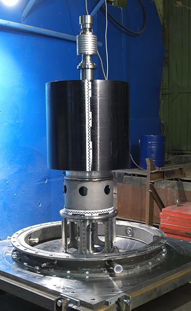
International Scientific Electric Power Conference – 2019                                  IOP Publishing
IOP Conf. Series: Materials Science and Engineering 643 (2019) 012106 doi:10.1088/1757-899X/643/1/012106

                           Table 1. Comparative characteristics of storages.
   Technology                                  Battery                                Flywheel system
List of Parameters            GEL                NiCd                 Li-ion
  Specific power,            30…90            150…300               150…315              400…1600
       W/kg
  Cycle life time           100…400            1000…2000            500…2500                 107
     Life time                2…10               10…15                 5…10                 >20
   Efficiency, %             70…85               65…80                80…95                96…98

2. Major directions of FESS usage

2.1. Frequency adjusting in power supply
FESS has been used in power systems for a long time [2,3]. Primarily they are used in grid companies,
and this allows one to smooth the consumption and load peaks, adjust frequency and voltage, and
reduce losses at transmission and regulation of reactive power. The most famous developments are
that from Beacon Power. These are commercially available stationary storages of 6 and 25 kWh
accumulated energy, as well as Beacon 400 storages and their modifications (400 Modular and 450
XP). Clusters of these storages are used to control the current frequency of US power grids. These are
regulatory plants based on Smart Energy Matrix 0.5 MW (Tyngsboro, MA), 20 MW (Stephentown,
NY) and 20 MW (Hazle, PA) [5,6] complexes.

2.2. The use of energy storage devices in power systems with RES
Allows one to: align variable work schedules; reduce power fluctuations; ensure the required quality
of electricity; provide uninterrupted power supply to consumers [7]. In 2003, the Japanese company
Fuji Electric installed 200 Urenco flywheels with a total capacity of 1,800 kW at Dogo Island in
Japan. The use of FESS helped to reduce fluctuations in the system, allowed the diesel generator
system to operate with greater efficiency, which led to significant savings of diesel fuel [8].
    The M32 super-flywheel developed by Enel and Amber Kinetics should be mentioned while
considering FESS used with RES. This steel flywheel weights 2 267 kg, is able to spin up to 10 000
rpm, its energy capacity is 32 kWh (115.2 MJ) and it is capable of delivering 8 kW of power for 4
hours [9]. The design of the super flywheel is based on the 2015 design of Amber Kinetics, i.e. FESS
with an energy capacity of 25 kWh [10.11]. In the spring of 2018, Hawaiian Electric, in collaboration
with Amber Kinetics and Elemental Excelerator, began testing M32 FESS at the generating station
Campbell Industrial Park at the Hawaiian island of Oahu to integrate RES into the network [12].
    FESS is successfully used in microgrids (MicroGrid) to stabilize the network with RES. The
leading positions in this direction are occupied by ABB, which produces stabilizers of the PowerStore
network of three nominal values: 500, 1000 and 1500 kW. Figure 1 shows the design solutions of the
ABB MicroGrid Plus system using FESS as a network stabilizer. The PowerStore, which is an element
of the MicroGrid Plus system, includes: FESS, inverters and special software (virtual generator). The
response time of such a system is less than 150 ms, and the overload capacity is up to 10 nominal
powers. The FESS of Piller technology with an energy capacity of 5 kW•h and a flywheel rotation
speed of 3600 rpm [13] is used as a PowerStore storage.

                                                    2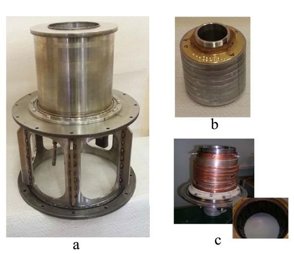
International Scientific Electric Power Conference – 2019 IOP Publishing
IOP Conf. Series: Materials Science and Engineering 643 (2019) 012106 doi:10.1088/1757-899X/643/1/012106
Figure 1. Implemented design solutions of MicroGrid networks by ABB using FESS as a network
stabilizer [14-16].
2.3. Hybrid energy storage systems with FESS
A promising way to develop energy storage technology is a hybrid energy storage scheme using FESS
and a rechargeable battery. This application allows one to get a fully balanced network that is resistant
to changes on the generation side and is independent of consumption. Examples of using this
technology are the system using Beacon 400 super-flywheels. One of these systems, consisting of two
drives of the Beacon 400 Modular series with a power of 160 kW and a lead-acid battery from Hitachi,
is installed in Ireland [17]. The next example of a hybrid energy storage system using FESS Beacon
400 is an innovative energy supply project in Anchorage, Alaska. [18,19].
ABB in its MicroGrid Plus systems also uses a hybrid energy storage scheme (PowerStore
stabilizer + RB). An example is the Chugach Hybrid Accumulation System (Chugach, Alaska, USA),
commissioned in 2017. Two PowerStore FESS operating in parallel reduce the peak load and reduce
the load on the existing RB-based energy storage system [20].
3. Superconducting FESS
Due to the progress and availability of superconducting passive magnetic bearing technology, a
number of FESS has been recently created using magnetic HTS bearings. In Japan, in 2015, Railway
Technical Research Institute jointly with Furukawa Electric Co., Ltd. and Kubotek Corporation
created the world’s largest-class superconducting FESS with a superconducting magnetic bearing. It
has 100 kWh (360 MJ) storage capacity and 300 kW output capability, and contains a carbon-fiber-
reinforced-plastic flywheel. This flywheel rotor is weighs 4 tons and 2 m diameter, and is suspended
by a superconducting magnetic bearing composed of superconducting coil (HTS-2 tape) and
superconducting bulks (YBa2Cu3Oy). This FESS is planned to be used as a power stabilizer for the
megawatt-class solar power plant at Komekurayama in Yamanashi Prefecture [21].
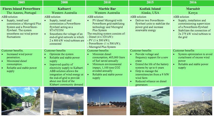
In Russia, in 2015, a FESS prototype with a magnetic HTS suspension with stored energy of more
than 5 MJ was created and tested in the framework of implementation of the Rosatom atomic energy
state corporation Innovative Energy / Superconducting Industry project (2011-2015) [22,23]. FESS
with a magnetic HTS suspension and its main technical characteristics are presented in Figure 2.
3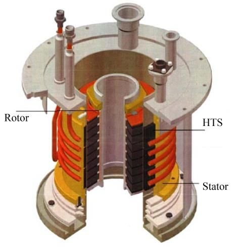
International Scientific Electric Power Conference – 2019                                  IOP Publishing
IOP Conf. Series: Materials Science and Engineering 643 (2019) 012106 doi:10.1088/1757-899X/643/1/012106

                       Figure 2. 5 MJ FESS with magnetic HTS suspension
                       and its main technical characteristics.
    The main structural elements of FESS (Figure 3) are: flywheel 1, motor generator 2, upper 4 and
lower 6 magnetic HTS suspension, magnetic bearing on permanent magnets (PM) 5 and mobile lower
bearing 7.
    The flywheel rotor of the 5 MJ FESS has a multi-layer construction (D16 aluminum alloy disc,
stainless steel pipe and carbon fiber bandage). Such flywheels are more reliable and safer in operation
than solid metal flywheels. In order to debug design methods and flywheel manufacturing technology
for a FESS prototype, a flywheel layout on a 1: 2 scale was designed, manufactured and tested. Figure
4 shows a photo of the flywheel during FESS assembly. The layout of the flywheel and the flywheel
of the FESS prototype were manufactured at JSC “VPO Tochmash”. Flywheel bandage is
manufactured at “Centrotech-SPb”.

 Figure 3. Scheme of the superconducting FESS.          Figure 4. Assembly of FESS with magnetic
                                                        HTS suspension.

                                                    4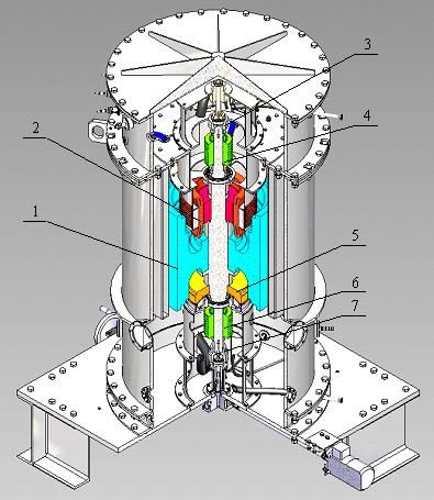
International Scientific Electric Power Conference – 2019                                  IOP Publishing
IOP Conf. Series: Materials Science and Engineering 643 (2019) 012106 doi:10.1088/1757-899X/643/1/012106

    The FESS rotating assembly is supported by a levitation system consisting of a magnetic support
and two cylindrical magnetic HTS suspensions located in the upper and lower parts of the flywheel
shaft. Magnetic support keeps the flywheel axially, and magnetic HTS suspensions provide radial
stability and partial compensation of the flywheel's weight. The magnetic support is made on the basis
of counter-magnetized conical ring permanent magnets (PM) of trapezoidal section made from
NdFeB.
    The main elements of HTS suspensions are stator and rotor. Figures 5 and 6 show the scheme of
magnetic HTS suspension and its main components. The magnetic suspension stator (Figure 6c)
contains a block with HTS elements based on yttrium ceramics (YBCO), which were made at the
Bauman Moscow State Technical University. Maintaining the temperature of the HTS stator elements
in the range from 65 to 75 K is provided by a closed-loop cryogenic system. At the stage of debugging
of the FESS prototype, the charge cryopreservation system was used.
    The rotor of the magnetic HTS suspension (Figure 6 b) consists of magnetic rings made of NdFeB,
which are arranged along the axis and connected by a liner. Spacers made of magnetically soft
material are located between the magnets, which provide formation of the necessary structure of
magnetic field in the gap between the rotor and the stator. HTS suspension of the FESS prototype was
designed and manufactured at MBDB “Horizont”.

Figure 5. Scheme of a magnetic HTS suspension.          Figure 6. Assembly of magnetic HTS
                                                        suspension: a - the lower suspension on the
                                                        support adapter; b - rotor; c - stator of lower HTS
                                                        suspension without outer casing with HTS unit.

   A developed synchronous six-pole electric machine with PM made of NdFeB with radial-tangential
magnetization and iron-free stator is used as a FESS motor-generator. The parameters of the motor-
generator are shown in Table 2.
                              Table 2. Parameters of the motor-generator.
                                List of Parameters                     Value
                   Rated power, kW                                      100
                   Phase voltage, V                                  230 – 380
                   Nominal current, A                                 156 – 96
                   Operating speed range, rpm                       5000– 8000
                   Number of poles, 2p                                    6
                   Number of phases                                       3
                   Stator outer diameter, mm                            428
                   Stator inner diameter, mm                            220
                   Stator length, mm                                    120

                                                    5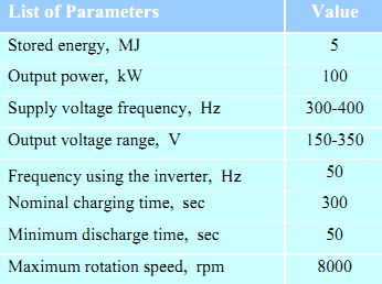
International Scientific Electric Power Conference – 2019                                  IOP Publishing
IOP Conf. Series: Materials Science and Engineering 643 (2019) 012106 doi:10.1088/1757-899X/643/1/012106

  Work on creation of 5 MJ FESS prototype with a magnetic HTS suspension has been successfully
completed. It was experimentally studied.

4. Conclusions
    The use of flywheel energy storage systems in autonomous electric power systems with RES
contributes to integration of RES into the network with an increase in their share in energy generation
system, an increase in reliability and stability of the energy system, as well as an increase in quality of
electricity for supplying consumers. Usage of new composite materials for fabrication of flywheels
makes such devices quite reliable and safe, allowing one to significantly increase the speed of rotation
of the flywheel, and accordingly, the energy intensity of the accumulation system. The use of magnetic
HTS bearings in FESS design increases the working life (more than 20 years) of the drive, thus
creating environmentally friendly energy storage systems with long shelf life of stored energy. Taking
into account such FESS advantages as scalability and modularity, “matrix” energy storage systems can
be built on the basis of a single FESS. These “matrix” FESS are intended for large levels of stored
energy and power, and can be both mobile (containers) and stationary

References
[1] RES come: 1000 GW of solar and wind generation. Cifrovaya podstanciya
        http://digitalsubstation.com/blog/2018/08/04/
[2] Awadallah M A, Venkatesh B 2015 Energy Storage in Flywheels: An Overview Canadian J. of
        Electrical and Computer Engineering 38(2) 183–93. doi:10.1109/cjece.2015.2420995
[3] Zakeri B, Syri S 2015 Electrical energy storage systems: A comparative life cycle cost analysis
        Renewable and Sustainable Energy Review 42 569–96. doi:10.1016/j.rser.2014.10.011
[4] Suzuki Y, Koyanagi A, Kobayashi M et al 2005 Novel applications of the flywheel energy
        storage system Energy 30(11) 2128–43.
[5] Eyer J 2009 Benefits from Flywheel Energy Storage for Area Regulation in California—
        Demonstration Results. Sandia National Laboratories (Albuquerque, NM, USA)
[6] Forbes. 2013 Beacon Power to Build a Flywheel Plant to Keep the Grid in Good Health. 18
        June 2015 Available online: http://www.forbes.com/
[7] Almari B R, Almari A R 2009 Technical review of energy storage technologies when integrated
        with intermittent renewable energy Proc. of Int. Conf. of Sustainable Power Generation and
        Supply SUPERGEN’09, 6-7 April 2009 1-5
[8] Gyuk I, Eckroad S 2004 EPRI-DOE. Handbook Supplement of Energy Storage for Grid
        Connected Wind Generation Applications. Technical Update 1008703
[9] ENEL, Viale E 2017 Enel signs agreement with US company Amber Kinetics on innovative
        flywheel storage system Press Release July 2017 (Rome)
[10] Amber Kinetics, Bryan Lee B, Pina F, Ten Hope L, Oglesby R 2015 Low-cost flywheel energy
        storage demonstration Amber Kinetics Final Project Report June 2015 CEC-500-2015-089
[11] Amber Kinetics 2015 Smart Grid Demonstration Program Contract ID: DE-OE0000232 Project
        Type: Flywheel Energy Storage Demonstration Amber Kinetics Technical Report (Final)
        Revision: V1.0. December 30, 2015
[12] Eyer J 2009 Energy Storage for the Electricity Grid: Benefits and Market Potential Assessment
        Guide Sandia National Laboratories, October 2009
[13] Schiller M, Rublevsky E 2017 MicroGrid. Challenges of the new time. Energiya razuma 2017,
        24-29
[14] ABB, William Galton. 2013 Stabilizing and maximizing renewables using a flywheel-inverter
        system. RPI CFES Workshop on Microgrid Technology and Applications : ABB, Oct. 2013.
[15] ABB, Cleiton S.2016 Renewable microgrids Reduced LCOE and secured supply August, 2016
[16] ABB 2015 Microgrid Solutions. Worldwide Installations. Local Grids Management Systems
        Workshop October 28, 2015

                                                     6
International Scientific Electric Power Conference – 2019 IOP Publishing
IOP Conf. Series: Materials Science and Engineering 643 (2019) 012106 doi:10.1088/1757-899X/643/1/012106
[17] Parnell J 2016 Flywheel-battery hybrid system installed in Ireland Energy Storage News 1 Apr
2016 https://www.energy-storage.news/
[18] Beacon Power 2014 TDX and Beacon Combine on Innovative Wind-Flywheel Energy Storage.
Press Release August 2014
[19] Beacon Power Beacon Power Flywheel Energy Storage Systems P/N: 0010010253 Rev - ECO
No: 1887
[20] Velazquez E 2017 Microgrid solutions. Integration of renewables and reliable power supply in
Alaska. Arctic Energy Summit September 19 (Helsinki).
[21] Mukoyama S, Matsuoka T, Hatakeyama H, Kasahara H, Furukawa M, Nagashima K at al 2015
Test of REBCO HTS Magnet of Magnetic Bearing for Flywheel Storage System in Solar
Power System IEEE Transactions on Appl. Superconductivity 25(3) 1–4.
doi:10.1109/tasc.2014.2363044
[22] Poltavets V, Kovalev K, Ilyasov R at al 2014 5 MJ flywheel based on bulk HTS magnetic
suspension. 11th European Conf. on Appl. Superconductivity (EUCAS2013). J. of Phys:
Conference Series 507 032022
[23] Poltavets V, Kovalev K, Kolchanova I, Ilyasov R 2015 V Int. Conf. on Fundamental problems
of high temperature superconductivity. The workbook of the extended abstracts October 5-9,
2015 (Moscow) pp 240-241
7You can also read