Enabling Display Measurement within Augmented & Virtual Reality Headsets - Optical Components Replicate Human Vision for Accurate Display Testing
←
→
Page content transcription
If your browser does not render page correctly, please read the page content below
WHITE PAPER

Enabling Display Measurement within
Augmented & Virtual Reality Headsets
Optical Components Replicate Human Vision for Accurate Display Testing
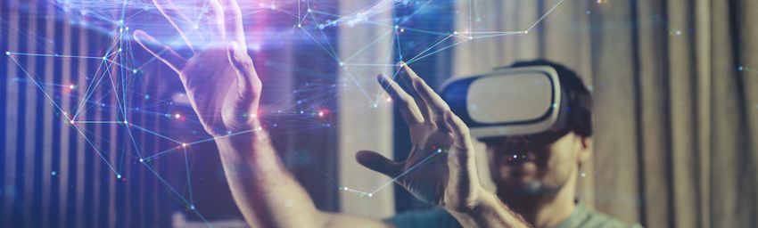
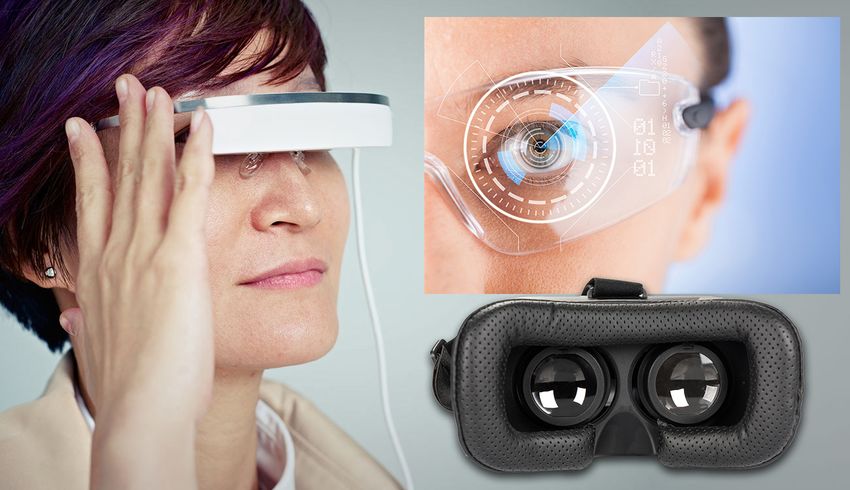
WHITE PAPER

Enabling Display Measurement within AR/VR Headsets
Optical Components Replicate Human Vision for Accurate Display Testing

Introduction
The application of augmented and virtual reality (AR/VR) devices is growing rapidly
in industries as diverse as gaming, military, education, transportation, and medicine.
According to the International Data Corporation (IDC), the AR/VR headset market is
expected to reach 81.2 million units by 2021, with a compound annual growth rate
(CAGR) of 56.1 percent.1 Every AR/VR device manufacturer takes a unique approach
to integrating displays within these headsets, and display technology and hardware
environments vary greatly. This market growth fuels an increasing need to measure
AR, VR, and MR (mixed reality) displays viewed near to the eye—together referred
to as near-eye displays (NEDs) (see Fig. 1)—using methods that are adaptable to the
geometries of each device and the different display specifications.

Figure 1 - Examples of head-mounted NED designs including immersive headsets and
transparent augmented reality glasses.

The increasing importance of AR/VR technology demands control solutions that
ensure visual performance. However, achieving a quality, seamless visual experience
poses a challenge for device designers and manufacturers due to the limitations of
measurement systems. The power of displays viewed as near to the eye as possible—
like those in AR/VR devices—is their ability provide immersive visual input. However, as
images in these displays are magnified to fill the user’s field of view (FOV), defects in the
display are also magnified. These defects not only detract from the user experience, but
ultimately can damage a company’s brand image in this increasingly competitive new
marketplace. Effective display testing, therefore, is an emerging necessity.

To help manufacturers ensure display quality, Radiant’s AR/VR Lens paired with a
ProMetric® Imaging Photometer or Colorimeter provides unique optics engineered
for measuring NEDs, such as those integrated into virtual, mixed, and augmented

2   I   Radiant Vision Systems, LLC
WHITE PAPER

reality headsets. The innovative new geometry of the lens design simulates the size,
position, and binocular field of view of the human eye. Unlike traditional lenses where
the aperture is located inside the lens, the aperture of the AR/VR Lens is located on the
front of the lens to enable the connected imaging system to replicate the location of the
human eye in an AR/VR device headset and capture the entire FOV available to the user.

This paper discusses the challenges of NED measurement, introduces Radiant’s
integrated AR/VR Lens solution, and outlines the solution’s advantages for evaluating
the human visual experience in NED applications.

Challenges of Measuring NEDs
Market trends in AR/VR indicate a need to measure more displays that are:
            1) Viewed extremely close up
            2) Viewed with a wide field of view (immersive)
            3) Viewed within head-mounted devices (goggles, glasses, and headsets)

1. Displays Viewed Close Up
Viewed as close as possible to the eye, NED projections are magnified to create the
immersive experience (see Fig. 2). This proximity also magnifies potential display
defects. For example, light and color uniformity issues, dead pixels, line defects, and      Figure 2 - With the display in a fixed
inconsistencies from eye to eye become more apparent to the user when viewed close           position within AR/VR devices, an
up. The closer a display is to the eye, the more important display testing becomes.          extended horizontal FOV is leveraged for
                                                                                             an immersive experience.
Another characteristic of displays viewed at this proximity is their resolution. To create
visual realism of projections across the display, NEDs must have more pixels per eye.
However, this poses a challenge for display measurement as high display resolution and
pixel density in turn require higher-resolution measurement devices.

2. Displays Viewed with Wide FOV
Depending on the device, images in AR/VR displays are projected across a range
of FOVs. With human binocular vision covering approximately a 114-120° horizontal
FOV, several leading commercially-available AR/VR NEDs (primarily VR) achieve FOVs
ranging between 100-120° (see Fig. 3).

Figure 3 - FOV comparison of VR headset displays. Source: VRGlassesHeadsets.com.2

3   I   Radiant Vision Systems, LLC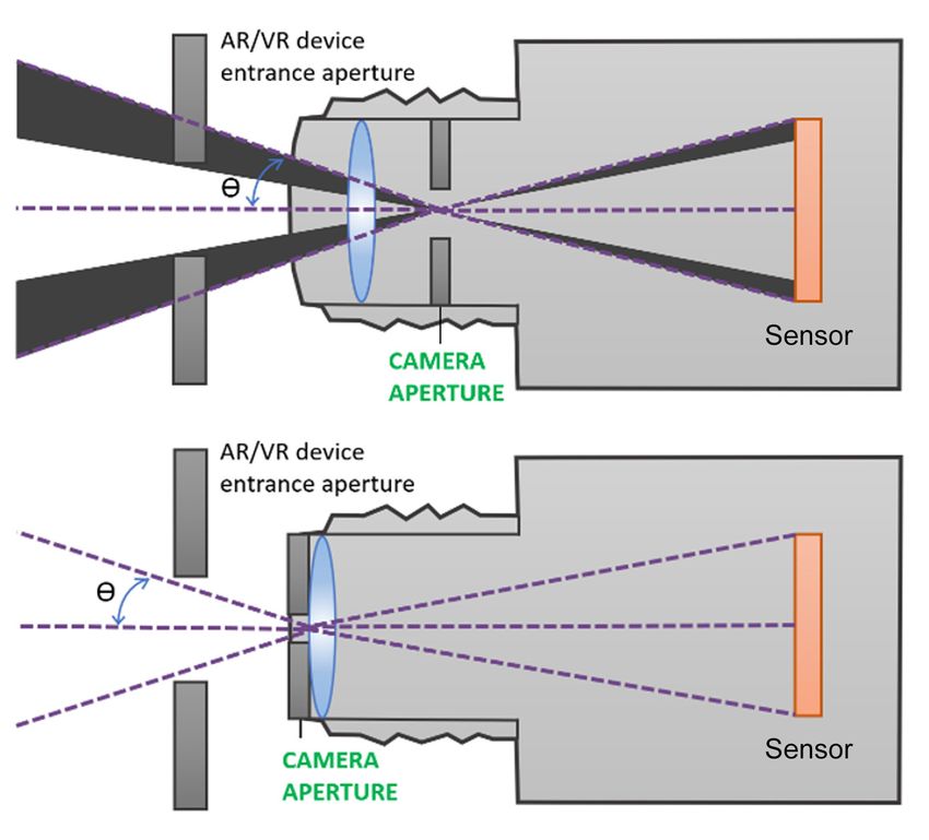
WHITE PAPER

The wider the FOV of the display, the more challenging it becomes to comprehensively
capture all areas of the display using an imaging system for measurement.

3. Displays in Head-Mounted Devices
NEDs are typically integrated within a head-mounted device (HMD), such as a headset
or goggles. To measure a display as viewed by a human user wearing such a device,
the measurement system must be positioned within the headset hardware at the same
position as the human eye (see Fig. 4). The measurement system’s entrance pupil (the
optical aperture) must emulate the human pupil position within the headset in order to
capture the full FOV of the display through the viewing aperture of the headset.
                                                                                             Figure 4 - A NED measurement system
Additional Unique Measurement Criteria                                                       positioned within the headset at the same
Display testing in AR/VR applications demands unique image characterization data and         location as the human eye can accurately
analyses. For instance, luminance (brightness of the projection) and color uniformity are    capture the display FOV as it is meant to
critical when combining images from eye to eye, or when images are overlaid on top of        be seen by the device user.
the surrounding ambient environment (as in AR).

Image sharpness and clarity are important when displays are viewed near to the eye,
and testing for these characteristics is performed using an MTF (modulation transfer
function) test method. Characterizing image distortion caused by the viewing goggles
or display FOV is key to improving spatial image accuracy and projection alignment.
An AR/VR measurement solution should include analysis functions for these common
criteria, as well as repeatable, consistent data to ensure device-to-device accuracy.

Measurement Approaches
Emerging AR/VR technologies require an innovative approach to display testing,
including new methodology, software algorithms, and—most critical for in-headset
measurement—optical geometries. Many technologies exist that attempt to meet the
unique testing criteria for AR/VR devices, but have significant limitations when it comes
to comprehensively addressing all of the measurable AR/VR display characteristics.
Some traditional measurement approaches are outlined below.

Machine Vision Cameras
The key limitation of machine vision is that it is not appropriate for absolute luminance
and color measurement (see Fig. 5). Traditional machine vision systems capture relative
data only—they do not provide metrological data to measure absolute luminance
or color as visualized by the human eye in an illuminated display. To perform a
true qualification of AR/VR displays as they are experienced by a human user, the
measurement system should provide photometric values. Imaging photometers and
colorimeters capture luminance and chromaticity values as they are perceived by
the human eye. This is achieved using integrated optical filters that expose specific
wavelengths of light to the camera’s image sensor. This process replicates the human         Figure 5 - Machine vision cameras
photopic response. Photometric imaging systems are commonly used for display                 are imaging solutions that locate and
testing, as they capture a complete display FOV in a single two-dimensional image to         measure features using relative data only.
analyze photometric data in a spatial context. This context is critical for evaluations of
uniformity, distortion, clarity (MTF), contrast, and image position.

4   I   Radiant Vision Systems, LLC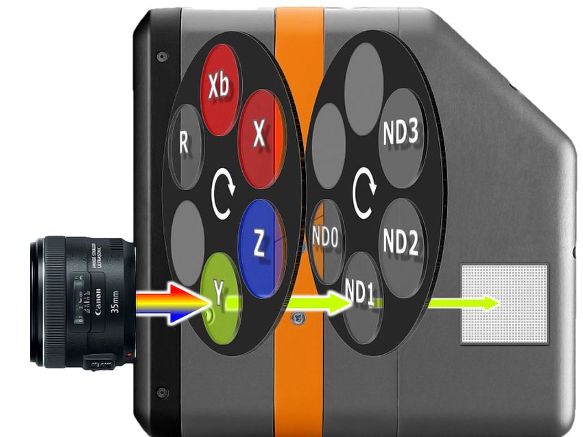
WHITE PAPER

Testing pixel-dense displays like NEDs also requires a measurement system with high
resolution and signal-to-noise ratio. Machine vision is typically employed to accomplish
extremely fast, repetitive measurement of visual characteristics that are identified based
on clearly discernible contrast differences. Many traditional machine vision systems
therefore sacrifice resolution for speed, offering low-resolution sensors that capture a
high ratio of image noise compared to the signal they receive. Display defects, however,
may occur at a level of detail as precise as a single display pixel. If a measurement
system cannot discern a defect in a high-resolution display from one pixel to the next,
it may miss defects that would appear obvious to a human viewing the NED. Systems
with high resolution and signal-to-noise are imperative for measuring displays in near-
eye applications with the same precision as the human eye (these systems may include
                                                                                             Low-resolution cameras are inadequate
scientific-grade image sensors that are electronically cooled and temperature stabilized
                                                                                             for measuring displays used in AR/VR
to further reduce noise received per sensor pixel).
                                                                                             devices. They may miss dots, particles,
                                                                                             dead pixels, or other small defects that
Limited-Resolution Cameras
                                                                                             would be apparent when viewing the
As discussed, measurement solutions that use low-resolution sensors are a poor fit for
                                                                                             display close-up. These systems are
testing the high-resolution displays that are used in near-eye viewing applications. The
                                                                                             also incapable of MTF measurement to
human eye is one of the highest-resolution “imaging” mechanisms there is—estimated
                                                                                             evaluate image sharpness.
to be around 576 megapixels (MP). For this reason, low-resolution imaging systems
(even photometry-based systems) will never catch all of the defects that a human user
would notice at the proximity of an AR/VR display.

Low-resolution cameras are inadequate for measuring displays used in AR/VR devices.
They may miss dots, particles, dead pixels, or other small defects, and are incapable of
accurate MTF measurement, which indicates the NED device’s ability to project images
at a certain sharpness or clarity. In order to acquire MTF measurements with accuracy,
images captured for analysis must be unaffected by the imaging system’s resolution. A
high-resolution imager isolates image clarity (MTF) issues of the NED device.

Standard Optics
Standard optical solutions are not designed for measuring within NED environments
(headsets, goggles) from the vantage point of a human user. This is a limitation of
traditional optical hardware design. For example, a traditional 35 mm lens has an
internal aperture. This aperture position causes occlusion of the full FOV of the display
due to obstruction by the lens housing and NED device’s entrance aperture (see Fig 6).

Figure 6 - Standard lens with an internal aperture.

5   I   Radiant Vision Systems, LLC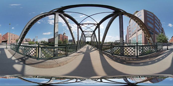
WHITE PAPER

Additionally, standard lenses are typically too large to fit inside NED headsets and
goggles at the eye position. The length and width of these lenses prohibits the              Human visual perception should
connected imaging system’s entrance pupil from being positioned where a human                provide the standard for performance
user’s eye would be, preventing measurement of displays as they are viewed in use.           measurement of NEDs. Like the human
                                                                                             eye, a NED measurement solution must
Custom Optics                                                                                be able to capture the full FOV of the
A custom-built optical solution is generally not viable for NED display testing within       display to address the range of display
headsets due to expense, long development time, and minimal scalability to meet future       characteristics that can be seen.
applications. Relying on in-house design also limits product support through the lifetime
of the solution.

Custom Software
To accomplish the unique image analysis functions required for AR/VR display testing,
some manufacturers may elect to customize a software component in-house. This
has similar downsides to customizing the optical hardware component, including
increased expense and time to implement, along with minimal scalability for future
requirements, limited product support, and inability to apply software for other display
test applications.

Replicating the Human Visual Experience
Human visual perception of display quality should provide the standard for optical
performance measurement of NEDs. Like the human eye, a NED measurement solution
should address the range of display characteristics that can be seen. Measuring a
display integrated within an immersive or head-mounted system relies on accessing
the display at the appropriate visual position to capture the full FOV that is meant to be
viewed by the human user. To replicate human vision for NED measurement, there are
several key elements that must be addressed by the display test equipment.

Photometric Measurement

Most essential to the visual quality of any display is the appearance of light and color.
Imaging photometers and colorimeters are best suited to evaluate visual display
qualities because they are engineered with special tristimulus filters (see Fig. 7) that
mimic the response of the human eye to different wavelengths of light (the photopic
response curve). A NED measurement system should employ photometric technology
using filters to evaluate light values as they are received by the human eye.

Full Field of View                                                                           Figure 7 - Imaging photometers and
                                                                                             colorimeters capture luminance and
Within the NED headset, the user is meant to have visual access to the entire FOV            chromaticity values as they are perceived
projected by the display—and therefore may notice defects at any point on the display.       by the human eye, using integrated filters
Imaging photometers and colorimeters need only one image to capture the display in           to expose each wavelength of light at a
full. Like the human eye, an imaging system can see all details in a single view at once.    different duration to the image sensor to
Using wide-FOV optics, an imaging system can capture a wide-FOV display even as it           replicate the human photopic response.
is viewed close up—simulating human binocular vision. Photometric imaging systems
paired with wide-FOV optics are therefore recommended for the most accurate and
comprehensive NED measurement.

6   I   Radiant Vision Systems, LLC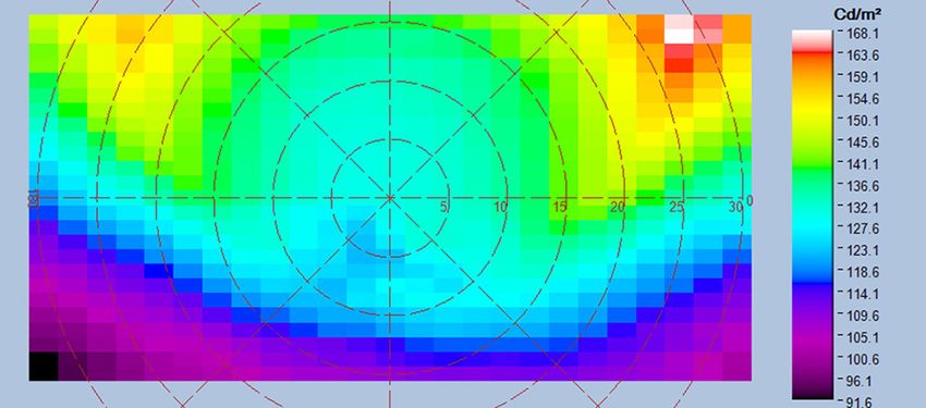
WHITE PAPER
High Resolution
AR/VR displays are meant to be viewed extremely close to the eye, which is itself a
high-precision imager. Therefore, NEDs are some of the highest-resolution displays,
fitting the most pixels in the smallest form factor for a seamless visual experience of
images close up. The system used to measure an integrated AR/VR display should have
sufficient resolution to capture all details in pixel-dense displays that may be visible
to the human eye at close range. Given sufficient resolution of the imaging system’s
sensor, each display pixel can be imaged across several sensor pixels, enabling pixel-
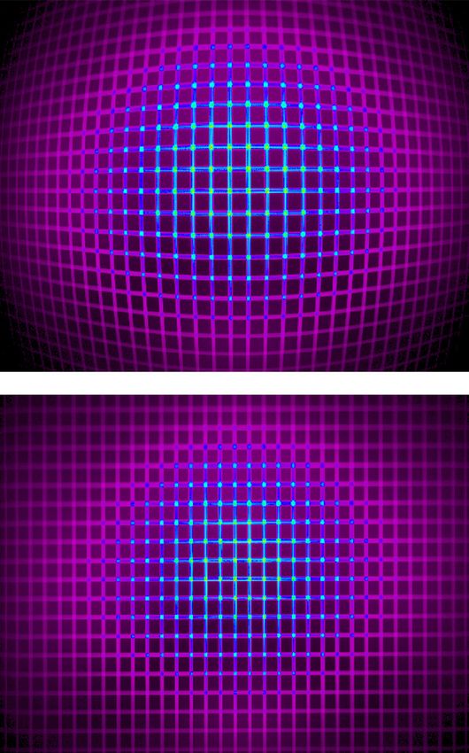
level defect detection (see Fig. 8).
Aperture
One of the greatest challenges in measuring near-eye displays within headsets is
positioning the measurement device in such a way as to view the entire display FOV
Figure 8 - The top image shows the raw
beyond the goggles. If the measurement system can obtain an image of the full display
image captured by a high-resolution
FOV as the user sees it, tests can be applied to evaluate any defects that may be visible
photometric imager. On the bottom, an
to the user during operation of the device. The challenge is that the human eye is at
analysis has been applied to detect tiny
a very particular position within AR/VR headsets. A display measurement system that
pixel-level defects. Close-up viewing
replicates the size, position, and FOV of human vision within the headset is necessary
in the AR/VR headset may make such
for capturing an image of the display for evaluating all qualities that the user may see.
defects apparent to the human eye.
Unique optical parameters that enable imaging systems to capture the full visible FOV
include the lens aperture position and geometry. In an optical system, such as the lens
on a camera, the aperture or “entrance pupil” is the initial plane where light is received
into the lens. A similar point exists in the pupil of the human eye.
Aperture Size
Replicating the human entrance pupil in NED measurement systems by achieving the
appropriate aperture size is important for several reasons:
1. An aperture that replicates the size of the human entrance pupil captures equivalent
light (equivalent detail) of the display as the human eye.
2. If the measurement system aperture is smaller than the human pupil size, the
imaged display appears sharper, with fewer/less severe aberrations than what the
human observes. (Display qualification may yield false positives.)
3. If the measurement system aperture is larger than the human pupil size, the imaged
display appears to have more aberrations than what the human observes. (Display
qualification may yield false negatives.)
Replicating the size of the human entrance pupil enables the imaging system to capture
images equivalent in detail and clarity to those viewed by the human eye and make the
same determinations of quality.
Aperture Position
Simulating the human eye position within AR/VR headsets is a critical objective for
integrated NED measurement. A traditional 35 mm lens has an internal aperture, which
cannot capture the full FOV of the display due to obstruction by the lens housing
7 I Radiant Vision Systems, LLC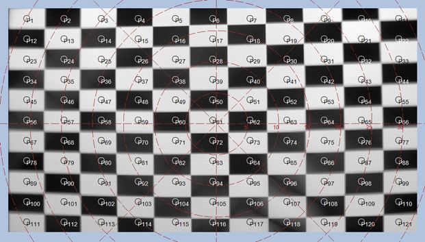
and the NED device hardware (the edges of the device’s entrance aperture) (see Fig.
9). Optical components designed with the aperture in front of the lens replicate the
intended position of the human eye inside the headset. Combined with wide-FOV
optics, an imaging system with aperture at the front of the lens can capture the full
display FOV and test for all visible characteristics that will be seen by the human eye.

                                                                                           Figure 10 - “Knot-hole” example: Top,
                                                                                           the entrance pupil is far from the opening
                                                                                           (knot hole), providing a limited view of the
                                                                                           image. Bottom, the entrance pupil is at
                                                                                           the opening providing a fuller view.

Figure 9 - NED measurement requires a unique optical design that positions the camera
aperture at the front of the lens, at the same location as the human eye, enabling
visualization of the complete FOV of displays as viewed through headsets or goggles.

This effect is like viewing a scene through a knot hole in a fence (see Fig. 10)—when
the eye is position at the hole, the full FOV can be seen beyond the fence. As the eye
moves away from the hole, the view becomes occluded by the edges of the fence.

Radiant AR/VR Measurement Solution
Radiant developed an AR/VR Lens to address the unique challenges of qualifying
integrated NEDs under the same conditions as they are visualized by human users. The
AR/VR Lens is designed to be paired with high-resolution imaging photometers and
colorimeters, in 16-, 29-, or 43-megapixel models (see Fig. 11). By capturing displays
at this detail, the measurement system can evaluate the entire display FOV at once with
the precision to capture any defects that might be noticeable to the human eye.

Figure 11 - The Radiant AR/VR Display Test Solution includes (left to right): AR/VR
Lens, ProMetric® Imaging Colorimeter or Photometer (16, 29, or 43MP options), and
TrueTest™ Software with optional TT-ARVR™ module.

8   I   Radiant Vision Systems, LLC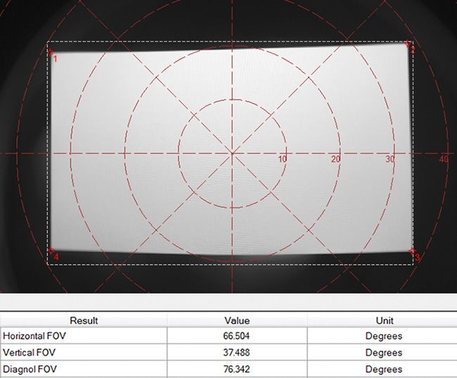
In-Headset Display Measurement

Radiant’s AR/VR display test solution is specially designed for in-headset display
measurement. What separates the AR/VR Lens from other optical components is the
lens’s ability to replicate the FOV and entrance pupil of human vision. The AR/VR Lens
product specifications include:

1.       Aperture (entrance pupil) located at the front of the lens.
2.       3.6 mm aperture size. The average pupil will contract to 1.5 mm in diameter in
         bright light and dilate to 8 mm in diameter in darkness. Radiant uses 3.6 mm for
                                                                                                   Figure 12 - Radiant’s AR/VR Lens
         two reasons: 1) it is in the mid-range of pupil dilation; 2) the 3.6 mm aperture allows
                                                                                                   replicates the human eye position in
         a high MTF for the lens.
                                                                                                   headsets for wide-FOV NED testing.
3.       Wide FOV to 120° (±60°) horizontal.

Importance of Calibration

Each Radiant AR/VR camera/lens system is factory calibrated to ensure the most
accurate images for absolute light and color analysis. Calibration processes include
factory distortion calibration to remove lensing effects of the wide-FOV lens, ensuring
accurate spatial analysis of the display by the camera software.

When measuring displays using a wide-FOV lens, the image captured by the lens
may appear distorted (see Fig. 13). Because the AR/VR solution uses a fisheye lens,
an uncalibrated image exhibits barrel distortion. Radiant’s camera/lens solution is
calibrated to process out distortion effects before applying display tests. This ensures
accuracy of spatial measurements to detect defects where they occur on the display.

Solution Software

Radiant TrueTest™ Automated Visual Inspection Software applies analyses to all images
captured by Radiant’s AR/VR measurement solution. This platform includes a suite of
display tests with standard tests for luminance, chromaticity, contrast, uniformity, and
defects like dead pixels and lines. In addition, unique tests for AR/VR projections are
available in the pre-configured TT-ARVR™ software module (see Table 1).

    TT-ARVR™ Software Module Tests
                                                                                                   Figure 13 - Top, an image captured
    •     Uniformity                               •    Points of Interest
                                                                                                   by an uncalibrated wide-FOV system;
    •     Line Defects                             •    MTF Slant Edge
                                                                                                   bottom, image captured by a system with
    •     Particle Defects                         •    MTF Line Pair
                                                                                                   distortion calibration applied.
    •     ANSI Brightness                          •    Distortion
    •     Sequential Contrast                      •    Focus Uniformity
    •     Checkerboard Contrast                    •    Pattern Mura
    •     Chromaticity                             •    Field of View (Device FOV)

Table 1 - Display tests in Radiant TT-ARVR™ software module.

9    I   Radiant Vision Systems, LLC
Some examples of TT-ARVR software analyses are shown in Figures 14-16 below.
These analyses are performed on the AR/VR display to test the manufacturing
specifications of the AR/VR device. These specifications can also be published for
consumer use (for instance, on an AR/VR headset specification sheet) to help them
evaluate the device and compare with competitive products.

Uniformity analysis (see Fig. 14) determines areas of low or high luminance across the
display, which may indicate a defect in the display. This analysis can also be used to
characterize the uniformity against design specifications.

                                                                                              Analyses performed on the AR/VR display
                                                                                              can be used to qualify the display, or
                                                                                              may be published (for instance, on an
                                                                                              AR/VR headset specification sheet) to
                                                                                              help consumers evaluate the device and
                                                                                              compare with competitive products.

Figure 14 - Uniformity analysis (shown in false color) characterizes display quality.

A checkerboard contrast analysis (see Fig. 15) is performed by projecting a
checkerboard pattern on the display within the AR/VR headset. Once the pattern is
imaged by the AR/VR test system, the checkerboard contrast test evaluates luminance
levels in the image to determine the display system’s ability to project distinct light and
dark values—a performance parameter that can be indicated on a specification sheet.

Figure 15 - Checkerboard contrast analysis evaluates the contrast ratio of the display.

A Field of View test (see Fig. 16) measures the actual field of view of the display
as imaged within the headset, ensuring that the horizontal, vertical, and diagonal
dimensions are correct to design specifications. These measurements can also be
reported on a specification sheet for an AR/VR headset.

10   I   Radiant Vision Systems, LLC
Figure 16 - Field of view analysis measures the display FOV within the NED device.
Conclusion
New display integration environments—like AR/VR and other head-mounted devices—
require designers and manufacturers to implement effective methods to test the optical
quality of displays that are viewed close-up, from a fixed position, within headset
hardware. Standard display measurement equipment lacks the optical specifications to
capture displays within headsets to evaluate the complete visible FOV as experienced
by the human user.
Radiant’s AR/VR display test solution is the only commercially available measurement
system with unique optical components that replicate the human pupil size and position
within AR/VR goggles and headsets to capture a display FOV to 120° horizontal.
The system offers the high resolution and efficiency AR/VR device makers require,
employing a compact camera/lens solution to capture all details visible across the NED
in a single image to quickly evaluate the human visual experience.
References
1. International Data Corporation (IDC). (2017, March). IDC’s Worldwide AR/VR
Headset Tracker Taxonomy, 2017. https://www.idc.com/tracker/showproductinfo.
jsp?prod_id=1501
2. VRGlassesHeadsets. (2017, March). VR Headset Comparisons: Field of view.
The Top VR Headsets Compared. http://vrglassesheadsets.com/vr-headset-
comparisons-field-of-view
11 I Radiant Vision Systems, LLCAcross industries, the increasing importance of virtual and augmented reality
(VR/AR) technology demands control solutions that ensure quality visual
experiences. This paper discusses the challenges of measuring near-eye displays
as they are viewed by the user of an AR/VR device, and explains the benefits of
Radiant’s integrated AR/VR Lens solution for in-headset display testing.
GLOBAL OFFICE LOCATIONS
Radiant maintains direct sales, engineering, and support offices and personnel throughout
North America, China, and Korea. Radiant is also sold and supported in other areas of the
world by our sister offices in the Konica Minolta Sensing Business.
AMERICAS EUROPE
Global HQ Radiant Vision Systems Europe HQ Nieuwegein, Netherlands
18640 NE 67th Ct.
Redmond, WA 98052 USA Regional Offices Diegem, Belgium
+1 425 844-0152 Paris, France
Info@RadiantVS.com Munich, Germany
Milan, Italy
Regional Offices Cupertino, California Wrocław, Poland
Novi, Michigan Vastra Frolunda, Sweden
Dietikon, Switzerland
Istanbul, Turkey
ASIA
Warrington, United Kingdom
China HQ Shanghai, China
Regional Offices Shenzhen, China
Suzhou, China
Japan Tokyo, Japan
Korea Seongnam, South Korea
Taiwan Zhubei, Taiwan
Asia-Pacific Singapore
Contact your local Radiant office at www.RadiantVisionSystems.com.
Copyright ©2020 Radiant Vision Systems LLC. All rights reserved. Specifications are subject to change without notice.
Radiant, Radiant Vision Systems, ProMetric, ProSource, VisionCAL, and Source Imaging Goniometer are registered
A Konica Minolta Company trademarks of Radiant Vision Systems LLC. 2020/07/31You can also read