HIFI-ELEMENTS: AN INTERFACE MODEL STANDARD AND WORKFLOW FOR HIGH FIDELITY ELECTRIC VEHICLE MODELLING AND TESTING
←
→
Page content transcription
If your browser does not render page correctly, please read the page content below
Proceedings of 8th Transport Research Arena TRA 2020, April 27-30, 2020, Helsinki, Finland

 HiFi-ELEMENTS: An Interface Model Standard and Workflow
 for High Fidelity Electric Vehicle Modelling and Testing
 Jens Ewalda*, Thorsten Schnorbusa, Markus Deppeb, Hassen Hadj-Amorc, Christian
 Granrathd, Jakob Andertd
 a
 FEV Europe GmbH, Neuenhofstraße 181, 52078 Aachen, Germany
 b
 dSPACE GmbH, Rathenaustr. 26, 33102 Paderborn, Germany
 c
 FEV STS SA, 11 rue Denis Papin, CS 70533 - Trappes, France
 d
 RWTH Aachen University, Templergraben 55, 52056 Aachen

Abstract

The results of the HORIZON 2020 project “HIFI-ELEMENTS” contribute to a more efficient development process
for e-vehicles. The goal is to reduce development and testing efforts by over 50%, decrease vehicle energy
consumption by up to 20% and increase validation test coverage up to 10-fold compared to current traditional
development approaches.
HiFi-ELEMENTS implements and investigates a streamlined workflow that makes the use of diverse modelling
tools for vehicle development inter-operable and more efficient. The proposal for a standardisation of functional
model interfaces related to the specific sub-components of an E-drivetrain vehicle, including: E-machine, inverter,
DC/DC-converter, and battery system is coupled with this new workflow. Existing standards like Functional
Mockup Interfaces (FMI) are incorporated. The proposed functional model interface component standard supports
a seamless use of models in the development process.
Furthermore, a scalable interface structure will be shown which implements a number of models using different
levels of detail. It allows the seamless transition from Real-Time (RT) low fidelity black-box models, suited for
Hardware-in-the-Loop (HiL) setups, to high fidelity models with detailed physical modelling.
HiFi-ELEMENTS investigates how a workflow with a linked co-simulation environment and data-management
application can speed up product development, with particular interest in front-loading system-level testing and
validation efforts.

Keywords: development process, e-vehicles, co-simulation, system modelling, component interface standard,
systems engineering.
Ewald et al. / TRA2020, Helsinki, Finland, April 27-30, 2020

Nomenclature

EV Electrical Vehicle
FMI Functional Mockup Interface
HiFi High Fidelity
HiL Hardware-in-the-Loop
LoFi Low Fidelity
MiL Model-in-the-Loop
RT Real Time
XiL X-in-the-Loop

1. Introduction

Vehicles and vehicle sub-systems are complex. In order to develop new vehicle generations with leading edge
technologies, the pooling of expertise from many different domains of science and technology is required with
close cooperation between the different partners and suppliers which are part of a wide supply chain. Furthermore,
these development processes must meet a wide range of requirements regarding time to market, continuous
reduction of cost and energy consumption as well as improvements in safety and comfort. These forces require a
more efficient development process. Increased virtualisation is regarded as a strategy to increase the efficiency of
development. Modelling and Simulation are two of these tools that are understood as part of virtualisation.
Simulation (“Virtual testing”) has earned its place in the automotive development process as a valuable
complement to physical tests. Physical tests are time consuming, costly and often of limited use in the early stages
of product development when hardware representative of design intent is not available.
The results of the HORIZON 2020 GV07 project “HIFI-ELEMENTS” contribute to a more efficient development
process for e-drive vehicles/EVs. The goal is to reduce development and testing efforts by over 50%, decrease
vehicle energy consumption by up to 20% and increase validation test coverage up to 10-fold compared to current
traditional approaches. HIFI-ELEMENTS started in October 2017. The finalisation of HIFI-ELEMENTS is
planned after 36 months in September 2020.
Developments in the past 10 years have made simulation a widely usable methodology. Today it is state-of-the-
art that the individual subcomponents and subdomains (e.g. electrical, thermal and mechanical) are being modelled
by different, domain specific, simulation platforms. There is no single modelling and simulation environment that
can cover all aspects of e-drive/EV development.
Another aspect is the challenge of defining the best strategy to include different simulation tools in each phase of
the development process. The currently commonly assumed process is depicted in Fig. 1 for the e-motor, the
battery, the vehicle and each of their controls. In parallel to the development of the EV components also their
corresponding control systems have to be developed. Both development processes, hardware component and its
control, respectively, undergo a V-type development process, starting from the requirement definition on the
system level to the detailing on the sub-system level and their verification of the performance until up to the system
level again.
In the concept phase, general decisions for the system and subsystem concept need to be made, using approximate
representations of each component behaviour (“Low Fidelity”, LoFi models) within a vehicle system model. It is
important to check the inter-operability of each component and their individual control strategies within the model
system. There is the severe risk that decisions on the concept are non-optimal since model assumptions in this
simulation phase are only approximate.
After the concept decisions for the system components have been made, investigations with models of higher
fidelity level (HiFi models) on individual component level are conducted. These models can be physically based
models — accessible from the outside — with calibrated model parameterisation or so-called IP-protected “black
box models” in which the physics from the outside are non-trackable. Judgements of model performance are made
against isolated requirements on component level. A feedback to the system representation is not possible in many
cases due to non-matching simulation interfaces or simulation environments.
At this time, the prototyping of the controls is started for Model-in-the-Loop investigation.
The further transition of HiFi component models to Model-in-the-Loop (MiL) investigation again requires a setup
of a new system model taking account of the different simulation environment. In addition, it is likely that also
required component model interfaces for MiL are different. Since these models in many cases exhibit execution
times which are slower than required for real time (RT) simulation or Hardware-in-the-Loop (HiL) environments,

 1

Ewald et al. / TRA2020, Helsinki, Finland, April 27-30, 2020

also the further transition to RT or HiL in many cases is not possible either. A system representation for RT/HiL
often needs to be recreated in the corresponding software environment again. This situation may lead to a late
control strategy calibration in relationship to the overall development process.

Fig. 1: Current development process. The lightning strikes indicate the limitations when transitioning from one development focus to the next
 one.

In consequence, many traditional approaches for simulation require more efforts and time to set up both tool chain
and the different simulation models, needed for example for a parameter or variation study. From this situation
also may result that a lower number of test cases are considered and less simulations are being executed than what
would technically be of interest.
In contrast to those traditional approaches, HiFi-ELEMENTS implements and investigates a streamlined workflow
that makes the use of diverse modelling and simulation tools inter-operable and more efficient. Coupled with this
new workflow is the proposal for a standardisation of functional model interfaces encompassing the specific sub-
components of an E-drivetrain vehicle, including: E-machine, inverter, DC/DC-converter, and battery system (at
cell, module and pack level). Existing standards like Functional Mockup Interfaces (FMI, Blochwitz 2011) provide
a formal interface format description under the assumption that the physical signals, data rates and data types have
previously been defined. The proposed functional model interface component standard — defining model
boundaries, signals and selected parameter data sets — will add a crucial element towards consistency and a
seamless use of models in the development process, see Fig. 2. The standard has been made public (HIFI-
ELEMENTS website) and can be used by any system and subsystem developer.

 2
Ewald et al. / TRA2020, Helsinki, Finland, April 27-30, 2020

 Fig. 2: New development process aimed by the results of HIFI-ELEMENTS

The proposed interface specification is developed using a Systems Engineering approach (Granrath 2019). In order
to promote model inter-operability and scalability, it is independent of the application used for the implementation
of the model. Furthermore, a scalable interface structure will be shown. It implements a number of models of
different levels of detail and allows the seamless transition from Real-Time (RT) low fidelity black-box models,
suited for Hardware-in-the-Loop (HiL) setups, to high fidelity models with detailed physical modelling for concept
development. This approach allows for a faster development of component models. For example, MiL developers
for the e-motor or the battery can start developing RT models and their controls while the system (i.e. vehicle) is
still in a concept model phase. Vice versa, concept models and RT models can be validated against each other
As further contribution, standardised e-vehicles topologies with pre-defined templates for individual components
for a number of different e-vehicle concepts are proposed. This is further explained in section 2.1.
Thirdly, HiFi-ELEMENTS employs a workflow with a linked co-simulation environment (e.g. xMOD, section
2.3) incorporating heterogeneous simulation platforms and data-management application (e.g. SYNECT, section
2.4). In combination with standardised functional model interfaces and an efficient, practical implementation of a
number of augmented modelling, simulation and testing tools it is investigated how this new workflow has the
potential to speed up product development, with particular interest in front-loading system-level testing and
validation efforts.

2. Proposed standard for e-vehicle modeling

2.1. Vehicle topologies

In order to provide a consistent subsystem definition that can be incorporated in a system modelling environment,
several layouts for different vehicle topologies on systems level are proposed, see Fig. 3.

 Fig. 3: Focused e-Vehicle Topologies

 3
Ewald et al. / TRA2020, Helsinki, Finland, April 27-30, 2020
Fig. 4: Reference Model used for HIFI-ELEMENTS.
The Reference System Model (see Figure 4) is a collection of all functional components. For several components
exactly only one entity is allowed, as for example Driver, Basic Vehicle and the Environment or the Thermal
System. Some components are optional, e.g. the transmission. For other remaining components, single or multiple
instances are allowed as they are placed at different locations in the vehicle topology. Signal management and
interface naming conventions need to account for the possibility that these multiple instances may occur.
In case that a component is not needed, the corresponding place for a functional model will be replaced by a generic
model that satisfies the interface requirements but otherwise provides no functionalities. In- and outputs of physical
signals are then connected together where this is physically meaningful, for example the input and output torque
at a position to be considered for the functional transmission model of the e-machine.
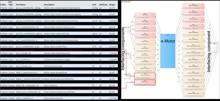
2.2. Interface Standard
Fig. 5: Exemplary interface description of the in- and outputs of an e-motor.
In Fig. 5 exemplarily the interface definition of the inputs and output interfaces of an e-motor is shown. The
definition of the interface names follows a naming convention standard which was defined in the beginning of the
project. In HiFi-Elements, the domain of the subsystem is defined by the limit of the individual component and
may divide accordingly the simulation domain (e.g. mechanical, thermal or electrical) in order to allow for a
consistent exchangeability of individual sub-components.
Next to signals in- and outputs, also certain fundamental simulation constants and model parameters are exchanged
using the naming convention standard. The standardisation approach also allows for task automation (i.e.
parameter calibration) and checking. The baseline proposal defines two different naming rules for signals and for
calibration (Santaroni, 2018).
The naming structure for interface signals is defined as:
{ }_{ }_{ }_{ },
4Ewald et al. / TRA2020, Helsinki, Finland, April 27-30, 2020
whereas the namespace is used to identify the signal feature and consists of two terms. The first term is the
mandatory component name which provides information about the signal source (i.e. battery, e-motor, etc.); the
second is the optional attribute which specifies the signal type (i.e. logical, physical, scalar, vector, matrix, map,
etc). The variable type specifies the quantity in terms of its physical nature Indeed, it can be physical (i.e. pressure,
temperature) or non-physical (i.e. flag). The variable description is a short concatenation of two or more terms
according to a defined list of abbreviations describing the physical location and a descriptive term which gives
additional information to identify the data item. Finally, in the field “Units” the specification according to the
shared measurement system (SI) is given.
An example is:
_T_ _ ,
which indicates a signal of the battery model (BAT), that is physically displayable (pd) and represents a minimum
cell temperature in the units of Kelvin.
For model or calibration parameters, it needs to be distinguished between 0D scalars - which can be accessed
directly - and multidimensional parameters, which also require the definition of the input axis variables for yielding
the result. Due to that fact, the following naming structure is used:
{ }_{ }_{ }_[ | | ][_ ] _{ } .
The Namespace is similarly defined as for the interface signals, however in this case the second term (attribute)
in this case is mandatory and specifies parameter type (scalar, axes of a calibration map, function calibration item
or map calibration item). The parameter description is defined in the same way as the description of the signal: a
short concatenation of two or more terms describing the physical location and a descriptive term which gives
additional information to identify the item.
In case that the parameter relates to multidimensional look up tables which require input, the field X|Y|Z is to
specify to which axes of the map/table or vector components the parameter is referred. Then, the input description
is to be given as well to describe the input parameter. Similarly, the Units field specifies the unit according to SI,
either as input, or as the resulting output parameter.
2.3. Co-Simulation
In order to allow for coupled simulations with heterogeneous simulation or XiL tools, a co-simulation based
workflow is introduced.
The co-simulation platform xMOD (Ben Gaid et al., 2010) provides a heterogeneous model integration
environment for models built by different persons using different languages and tools and working within different
entities. The implemented algorithms in combination with parallel computing on multi-core platforms allows to
execute simulation models embedding different solvers at different step-times, thereby speeding-up the execution
of complex simulations.
By means of the co-simulation environment, existing simulation models for system components and component
groups can be re-used and integrated into a simulation concept for the whole system, allowing unified access to
the inputs and outputs, for example in a common operating dashboard. Furthermore, the usage of the co-simulation
environment also allows the implementation of a standardized failure insertion method for validation tests,
regardless of the simulation environment used.
In addition, by means of the co-simulation platform, gaps within the tool chain due to the heterogeneous nature of
component models or hardware can be closed. While in the concept phase or during MiL simulation, the process
is carried out off-line, the HiL phase requires RT capability. On order to accomplish this, xMOD has been
developed on the RTX real time operating system (Intervalzero, 2014). Then, the simulation environment can be
used with high versatility for full virtual powertrain simulation or to mix virtual and real components using typical
communications protocol like EtherCAT, Real-Time Ethernet, CAN, fiber optics and also analog signals. This
approach can be extended to a test bed environment by embedding a real component in a virtual powertrain.
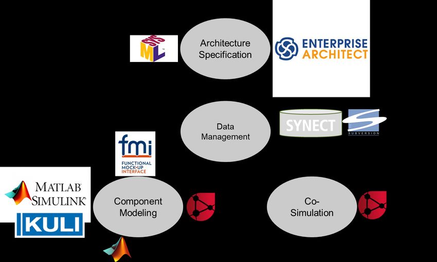
5Ewald et al. / TRA2020, Helsinki, Finland, April 27-30, 2020 2.4. Tool Chain Fig. 6: HiFi-Elements Toolchain The tool chain which is used in HiFi-ELEMENTS is composed of several software products as shown in Fig. 6: For management of simulation model variants, the data management software SYNECT is used. In order to implement the functional description of the components, software as MATLAB/Simulink, KULI or other proprietary software tools are employed. The system architecture specification and the functional component interfaces are compiled and managed in this specific project using the software Enterprise Architect. Exchange between functional model interfaces is done using the FMI 2.0 standard in parallel to MATLAB S-Functions or the XModel format of xMOD. The workflow is designed for a top-down approach starting with a definition of the system architecture variants in the modelling language SysML. The data management system SYNECT can import the system architecture variants and combines them with a formal variant model. It allows for the management of different vehicle system topologies as well as variants of component models. Setup and execution of simulations for different variants are facilitated by semi-automated tool support which leads to a speed-up of the development process. SYNECT also supports the storage of files in Subversion, the compatibility checks of models against the architecture definition, the creation of initial model files as stubs (hulls containing an interface level only) and the semi-automated integration of systems (vehicle level models) for co-simulation comprised of managed component models. In order to reduce the number of different architecture variants in the tool chain, it has been identified to be efficient to combine several vehicle architectures into a superset, the so-called “150%” architecture, see Fig. 7. Component models may have multiple positions within the superset architecture (i. e. an e-motor either connected to the front or the rear axle, or an optional HV DC/DC). In order to yield the actual (“100%”) required full architecture, the superfluous component position needs to be deleted. 6
Ewald et al. / TRA2020, Helsinki, Finland, April 27-30, 2020

Fig. 7: Illustration of the concept of the “150%” superset architecture, from which all considered architectures can be derived to full extent
(“100%”).

3. Results, Conclusions and Outlook

At the time of the creation of this report in March 2019, the first results in HIFI-ELEMENTS are available.
The naming convention for the functional interface signals as described above have been made public on the
official website of HIFI-ELEMENTS (https://www.hifi-elements.eu/). Further reports on the tool chain and other
selected reports are available there as well. All these reports can be accessed after registration on the website.
Project discussions have synchronised the requirements for the model developers and the end-users. While the
original focus only was on developing co-simulation and FMU/FMI compatible interfaces and workflows, the
developers and end-users have expressed also their requirements to also use SIMULINK S-Functions further.
Therefore, the latter approach was additionally regarded in the development.
As a consequence, also the tool chain needs to consider the different component model formats XModel, FMI 2.0
and S-Function to fully support the inhomogeneous requirements of the different project partners. Each format
supports IP-protection by a binary build result which is mandated by the partners. Multiple sample times and
structured data types are only supported by S-Functions and XModels. S-Functions are lacking a formal model
specification as supported by XModels and FMUs. This makes it difficult to formally check S-Functions for
interface compatibility in case of a system integration. FMI 2.0 additionally offers co-simulation features such as
event iteration for hybrid systems, caching of equation results and discarding/repeating of simulation steps.
In order to support signal and simulation based testing, a new domain specific language (DSL) has been developed
with the intention of easing the specification of automotive systems to engineers and to enable automated test
generation. This DSL is a language that allows model developers to formally specify requirements for signal-based
and simulation-based testing. Requirements of the models are formally specified within different files of the DSL.
These requirements need to formally specify the signals behaviour for given input conditions within a given
tolerance region.
In the remaining project time of HIFI-ELEMENTS, further exchange between other H2020-GV7 projects is
planned. The other projects have already indicated the interest to use the naming convention and vehicle
architecture as baseline in their projects.
Furthermore, we will exercise the development made in several use cases and show the capability of our developed
approach. For examples the use cases will demonstrate the e-motor replacement within a MiL environment as well
as e-motor-in-the-loop as HiL example, or will investigate the advantages of this new tool chain for battery back
and battery management system (BMS) development. In addition, the toolchain developed in this project will also
be employed to consider the optimisation of vehicles controls and integration for the upgrade of an existing vehicle
to an EV powertrain. The last use case will show the exchange ability of the different functional component models
within an already existing model tool chain on OEM level for general system optimisation. Results and conclusions
 7
Ewald et al. / TRA2020, Helsinki, Finland, April 27-30, 2020

of these use cases will be fed back into the simulation standards. It is the intention from HIFI-ELEMENTS that
these standards remain public and will found the basis for a general standard.

Acknowledgements

This project has received funding from the European Union’s Horizon 2020 research and innovation programme
under grant agreement No 769935.

References

Ben Gaid, M., Corde, G., Chasse, A., Léty, B., De La Rubia, R. and Ould Abdellahi, M., 2010. Heterogeneous Model Integration and Virtual
 Experimentation Using xMOD: Application to Hybrid Powertrain Design and Validation, EUROSIM'10, Prague, Czech Republic,
 September 2010.
Blochwitz, T., et al., 2011 "The functional mockup interface for tool independent exchange of simulation models." Proceedings of the 8th
 International Modelica Conference; March 20th-22nd; Technical University; Dresden; Germany. No. 063. Linköping University Electronic
 Press.
Deppe, M., 2018. HiFi-ELEMENTS Deliverable D1.2: SYNECT generated Component model reports, URL: https://www.hifi-elements.eu/
Deppe, M., 2018a. HiFi-ELEMENTS Deliverable D1.3: Document describing the workflow architecture, URL: https://www.hifi-elements.eu/
Deppe, M., 2019. HiFi-ELEMENTS Deliverable D3.1: Set of SYNECT Add-Ons to Import All Model Formats and Set of Frame Model
 Generators, URL: https://www.hifi-elements.eu/
Deppe, M., 2019a. HiFi-ELEMENTS Deliverable D3.2: Formalized Variant Model Represented in SYNECT to Cover All Scalability and
 Variability Aspects of Component Models and Parameter Sets, URL: https://www.hifi-elements.eu/
Enterprise Architect, Homepage, accessed on 17 April 2018, URL: http://sparxsystems.com/products/ea/
Functional Mock-up Interface, FMI Webpage, accessed on 17 April 2018, URL: http://fmi-standard.org/
Granrath, C., Meyer, M., Andert, J., Richenhagen, J., 2019 Antriebstechnisches Kolloquium 2019: (conference proceedings) p. 85-98, ISBN:
 3749407614, 9783749407613
HiFi-ELEMENTS website, URL: https://www.hifi-elements.eu/, 2018-2020
Intervalzero, 2014. RTX64: A Powerful, Flexible Platform for Industrial Vision Control Systems, URL: https://www.intervalzero.com/
Krammer, M. et al. 2018. The Distributed Co-Simulation Protocol for the Integration of Real-Time Systems and Simulation Environments
 SCS SummerSim 2018
Santaroni, L., 2018. HiFi-ELEMENTS Deliverable D1.1: Document describing the safety requirements and modeling guidelines, URL:
 https://www.hifi-elements.eu/

 8
You can also read


