Modeling Glioma Growth and Mass Effect in 3D MR Images of the Brain
←
→
Page content transcription
If your browser does not render page correctly, please read the page content below
Modeling Glioma Growth and Mass Effect in 3D
          MR Images of the Brain

             Cosmina Hogea1 , Christos Davatzikos1 , and George Biros2
    1
    Section of Biomedical Image Analysis, Department of Radiology, University of
                    Pennsylvania, Philadelphia PA 19104, USA
 2
   Departments of Mechanical Engineering and Applied Mechanics, Bioengineering,
and Computer and Information Science, University of Pennsylvania, Philadelphia PA
                                   19104, USA
                             hogeac@uphs.upenn.edu

         Abstract. In this article, we propose a framework for modeling glioma
         growth and the subsequent mechanical impact on the surrounding brain
         tissue (mass-effect) in a medical imaging context. Glioma growth is mod-
         eled via nonlinear reaction-advection-diffusion, with a two-way coupling
         with the underlying tissue elastic deformation. Tumor bulk and infil-
         tration and subsequent mass-effects are not regarded separately, but
         captured by the model itself in the course of its evolution. Our for-
         mulation is fully Eulerian and naturally allows for updating the tu-
         mor diffusion coefficient following structural displacements caused by
         tumor growth/infiltration. We show that model parameters can be esti-
         mated via optimization based on imaging data, using efficient solution
         algorithms on regular grids. We test the model and the automatic opti-
         mization framework on real brain tumor data sets, achieving significant
         improvement in landmark prediction compared to a simplified purely
         mechanical approach.

1       Introduction
Modeling brain tumor growth in conjunction with deformable registration al-
gorithms can be used to construct brain tumor atlases and potentially assist
treatment planning [1, 2]. In order to improve registration between a normal
brain atlas and a tumor-bearing brain image, it is desirable to first construct
a brain atlas exhibiting tumor and mass-effect1 similar to those of a patient at
study, thus reducing the problem to the (simpler) problem of registering two
relatively similar images.
   Therefore, we need a way to simulate tumor growth and mass-effects for dif-
ferent brain anatomies. In [1, 3, 4], a purely mechanical 3D tumor growth model
targeted on simulations of tumor mass-effect was employed. The brain tissue was
modeled as an elastic material (linear or nonlinear) and the mechanical force
exerted by the growing tumor was approximated by a constant outward pres-
sure P acting on the tumor boundary and controlling the tumor size and mass-
effect. This model was solved to obtain brain tissue displacements. Although this
1
    Deformation (compression) of the neighboring tissue induced by tumor growth is
    commonly referred to as mass-effect.

N. Ayache, S. Ourselin, A. Maeder (Eds.): MICCAI 2007, Part I, LNCS 4791, pp. 642–650, 2007.

c Springer-Verlag Berlin Heidelberg 2007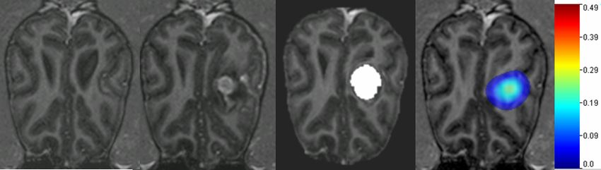
Modeling Glioma Growth and Mass Effect in 3D MR Images           643

approach was employed successfully for generating tumor-deformed brain atlases,
it has two main limitations: (1) more irregularly shaped tumors are difficult to
capture (the simulated tumors are generally quasi-spherical); and (2) it provides
no information about the actual tumor evolution and infiltration into healthy
tissue. In [2], the authors have used a relatively similar mechanical approach to
model the mass-effect caused by the tumor bulk (GTV1) and added a separate
reaction-diffusion model (similar to [5], [6], [7]) to account for the tumor infiltra-
tive part only (GTV2, assumed to cause little mass-effect). In such an approach,
the tumor reaction-diffusion equation is decoupled from the elasticity equations
and the diffusion coefficient, which in reality is affected by tumor infiltration, is
not updated [2].
   Here, we propose a model that strongly couples glioma2 growth with the
subsequent deformation of the brain tissue. Using brain tumor MRI scans, model
parameters can be estimated via a biophysically-constrained optimization formu-
lation of a deformable image registration problem. In our approach, glioma growth
is modeled via a nonlinear reaction-advection-diffusion equation, with a two-way
coupling with the underlying tissue elasticity equations. Our formulation (fully
Eulerian) naturally allows for updating the tumor diffusion coefficient following
structural displacements caused by tumor growth/infiltration. The overall model-
ing framework results in a strongly coupled nonlinear system of partial differential
equations, for which we use an efficient numerical solution procedure.
   The main differences compared to the work in [2] are: (1) there is no sharp-
interface separation between a tumor bulk and an infiltrative part; (2) the under-
lying tissue displacement (deformation) impacts the subsequent motion of the
tumor cells in two ways: the diffusion coefficient changes (diffusion term in the
tumor equation) and tumor cells are pushed around (advective term in the tu-
mor equation); (3) the diffusion coefficient, affected by structural displacements
following tumor growth and infiltration, is updated; (4) the numerical solution
algorithm is based on fast hybrid finite element-finite difference solvers on fixed
regular grids, coupled with an optimization algorithm for estimation of model
parameters from patient imaging data.

2     Methods
The brain is regarded as a deformable solid occupying a bounded region ω in
space. Let U = ω × (0, T ), where (0, T ) a specified time interval. Let c = c(x, t)
be the tumor-cell density, normalized such that 0 ≤ c ≤ 1. Using an Eulerian
frame of reference, the tumor growth and the subsequent brain motion can be
described by the following general set of equations:
                           ∂c
                              − ∇ · (D∇c) + ∇ · (cv) − ρc(1 − c) = 0            (1)
                           ∂t
                                                           p2
            ∇ · ((λ∇ · u)I + μ(∇u + ∇uT )) − p1 e− cs e− (2−c)s ∇c = 0
                                                   p2
                                                                                (2)
                                        ∂u       ∂m
                                     v=    ,           + (∇m)v = 0,             (3)
                                        ∂t        ∂t
2
    Malignant gliomas are the most common primary brain tumors, originating in the
    glial cells; they are often resistant to treatment and carry a poor prognosis.
644 C. Hogea, C. Davatzikos, and G. Biros
where m = (λ, μ, D). In regions where c 1 (infiltration), the customary pro-
liferation term ρc corresponding to exponential growth at rate ρ is retrieved [5].
Proliferation is assumed to slow down in regions with c getting closer to 1 (tumor
bulk), and it eventually becomes a death term if c becomes larger than 13 ; D
is the diffusion coefficient of tumor cells in brain tissue4 . Here we consider the
case of isotropic diffusion in both white and gray matter, with diffusion coeffi-
cients Dw and Dg , respectively [5]. v is the (Eulerian) velocity field5 , u is the
displacement field.
We employ the linear elasticity theory and approximate the brain tissue as
a linear elastic material, characterized by Lame’s parameters λ and μ (related
to Young’s modulus E and Poisson’s ratio ν). The elastic forces are pressure-
like, directly proportional to the local gradient of the tumor cell density [9],
[2]; the expression we use here, with p1 , p2 and s positive constants, allows for
flexibility in capturing both strong tumor mass-effect (generally caused by the
tumor bulk) and milder mass-effects (generally caused by tumor infiltration), as
illustrated in figure 1. The elastic material properties λ and μ and the tumor
cell diffusivity D are assumed spatially varying (different in white matter, gray
matter, ventricles, CSF). Boundary and initial conditions are specified to close
the system of equations (1)-(3). We impose zero tumor cell flux and zero tissue
displacement at the skull. The advection equations (3) are initial value problems,
with the initial values assigned from the corresponding segmented MR image
[3,4]. Equations (1)-(3) with prescribed boundary and initial conditions represent
a mixed parabolic-elliptic-hyperbolic nonlinear system of PDEs. Next, we outline
an efficient numerical algorithm for solving this system.
2.1 Numerical Methods
A significant challenge is posed by the fact that the underlying spatial domain
ω occupied by the brain is a highly irregular one. Various techniques exist for
solving PDEs on an irregular domain, from unstructured meshes that conform to
the irregular domain boundary to immersed interface/ghost-fluid methods. Here,
we employ a fictitious domain-like regular grid method. The target domain ω is
embedded on a larger computational rectangular domain (box) Ω. The PDEs
originally defined on ω, are appropriately extended to Ω, such that the true
boundary conditions prescribed on ∂ω are approximated.
For simplicity, it is advantageous to split the problem into independent steps
corresponding to the advection, diffusion, and reaction [10], [11]. Let w =
(c, u, v, D, λ, μ) denote the vector of unknowns. Let Δ, A1 , and R denote the
diffusion, advection and reaction operators in the diffusion equation (1), and A2
denote the advection operator in equations (3). Let wn = (cn , un , vn , Dn , λn , μn )
is the solution at time t = tn ; to update the solution wn+1 at the next time step
tn+1 = tn + Δt we use three steps.
3
We do model tumor as a single species and we ignore heterogeneity.
4
If tumor diffusion is assumed anisotropic, then D is a tensor.
5
The velocity v in the tumor equation may well depend on tumor specific mechanisms
(e.g., chemotaxis [8]). In our model the velocity accounts only for the tumor cells
being displaced as a consequence of the underlying tissue mechanical deformation.Modeling Glioma Growth and Mass Effect in 3D MR Images 645
(I) We solve the advection equations (3) over time Δt to obtain (Dn+1 , λn+1 ,
μn+1 );
(II) We solve the diffusion equation (1) using a simple fractional step method
∗
[10]: a) Solve ∂c n n
∂t = A1 (c, v) over time Δt with data (c , v ) to obtain c ;
∗
b) Solve ∂c
∂t = Δ(c, D) over time Δt with data (c , D
n+1
) to obtain c∗∗ ;
∂c ∗∗
and c) Solve ∂t = R(c) over time Δt with data c to obtain cn+1 .
(III) Finally, we solve the elasticity equation (2) with data (cn+1 , λn+1 , μn+1 )
to obtain un+1 and update the velocity vn+1 .
Parameter estimation (optimization)
Consider the case of longitudinal data for a brain-tumor subject. We seek to
compute the model parameters that generate images that ’best match’ the pa-
tient data. This translates into a parameter-estimation problem for the model
governing equations (1)-(3). Here we use an objective functional that defines a
‘best match‘ by the Euclidean distance between model-generated landmarks and
manually-placed landmarks in the target image(s). The results presented in the
next section are obtained using the APPSPACK package [12], a derivative-free
optimization library from Sandia National Laboratory. More efficient optimiza-
tion algorithms, based on gradient estimation via the adjoints [13], are work in
progress.
3 Results
Given the segmented image labels (generated from 3D MRI data), we assign
piecewise constant material properties (white matter, gray matter, ventricles,
and CSF). These values are used as initial condition in the transport equations
(3). The 3D computational domain is the underlying domain of the image. It
consists of the actual brain plus the surrounding fictitious material.
Synthetic brain tumor images
We first illustrate the capabilities of our proposed framework to simulate brain
tumors with more complex patterns and mass-effect. For the simulations in
Figure 1 we have used similar values for the elastic material properties as in
[3, 4]. The tumor diffusivity in the white matter was set five times higher than
in the gray matter [5], while the diffusivity in the ventricles (and eventually
CSF) was set to zero. These simulations correspond to an aggressive physical
tumor growth over T=365 days (one year), starting from the same small
Gaussian seed located in the right frontal lobe. The numerical solution of our
coupled system of PDEs (1)-(3) is obtained via the procedure described in sec-
tion 2.1 using a hybrid finite element-finite difference method, with ten equal
time steps and a spatial discretization of 65 × 65 × 65 nodes6 . The tumor
growth illustrated in the second column (left to right) of figure 1 is less dif-
fusive (Dw = 7.5 × 10⁻⁸ m2 /day;Dg = 1.5 × 10⁻⁸ m2 /day) and more regularly
shaped, while in the other two case scenarios depicted in the third and fourth
6
By extensive numerical testing, we have found that such a discretization provides a
reasonable trade-off between speed and accuracy.646 C. Hogea, C. Davatzikos, and G. Biros Fig. 1. Synthetic glioma growth, right frontal lobe: three different case scenarios start- ing from the same initial tumor seed. Left to right. The 1st column illustrates the 3D MRI of a normal brain image—axial, sagittal and coronal section respectively. The 2nd column shows the deformed image, with simulated tumor corresponding to low tumor diffusivity and long-range mass-effect (p2 = 0). The 3rd column shows the deformed image, with simulated tumor corresponding to high tumor diffusivity (ten times higher) and long-range mass-effect (p2 = 0). Finally, the 4th column shows the deformed image, with simulated tumor corresponding to high tumor diffusivity and short-range mass- effect (p2 = 0.1). The tumor maps (here shown in RGB) are overlaid on the deformed template. The run time is about 500 seconds on an 2.2GHz AMD Opteron. column (left to right) respectively, we increased the diffusivity by a factor of ten (Dw = 7.5 × 10⁻⁷ m2 /day;Dg = 1.5 × 10⁻⁷ m2 /day). For both simulations illus- trated on the second and third columns (left to right) of figure 1, the parameter p2 regulating the range of the mass-effect was set equal to zero, which is the minimum, corresponding to an extreme case scenario, with strong mass-effects propagating far away from the tumor core, which we refer to as ‘long-range‘ mass-effects. This can be well observed by examining the ventricle deformation in the corresponding axial slices. If p2 is increased, the mass-effects are more lo- calized to areas close to the tumor core, which can be well observed on the fourth column of figure 1 and which we refer to as ‘short-range‘ mass-effects. The rest of the model parameters are kept fixed to ρ = 0.036/day, p1 = 15kP a, s = 2. More complex tumor patterns could be obtained by using more complicated initial tumor profiles and/or anisotropic diffusion (DTI-driven). Optimization on real brain tumor data and comparison with simpler pressure-based mechanical model In [3,4], the authors have investigated the ability of their proposed framework to realistically capture mass-effects caused by actual brain tumors in two dog cases with surgically transplanted glioma cells and a human case with progressive low- grade glioma. We use their data sets here for comparison purposes. For the two
Modeling Glioma Growth and Mass Effect in 3D MR Images           647

Table 1. Landmark errors for the two dog cases (DC1, DC2) and for the human case
(HC) with the new model (optimized). The errors shown are with respect to landmarks
manually placed by an experienced human rater. Both the incremental pressure model
and the new model were numerically solved using a spatial discretization with 653
nodes; five equal pressure increments applied in the simple pressure model; four equal
time steps used in the new model for the two dog cases and five equal time steps for
the human case.

          Landmark Error (mm) Median Min Max Run time (sec)
                New model DC1            0.89564 0.0511 1.9377    200
           Incremental pressure model    1.6536   0.3176 2.6491   300
           Inter-rater variability DC1   0.8484   0.1304 2.8568
                New model DC2            1.2980   0.3803 2.6577   200
           Incremental pressure model    1.8912   0.4795 3.7458   300
           Inter-rater variability DC2   1.3767   0.1226 2.7555
                New model HC             1.8457   0.5415 4.1451   250
           Incremental pressure model     5.23     1.15   8.9     300

dogs (DC1, DC2), a baseline scan was acquired before tumor growth, followed
by scans on the 6th and 10th day post-implantation. Gadolinium-enhanced T1
MR images were acquired. By the 10th day, tumors grew rapidly to a diameter
of 1-2 cm, and then the animals were sacrificed (prior to any neurological com-
plications). For the human case (HC), two T1 MRI scans with approximately
2.5 years in-between were available. In all three cases, pairs of corresponding
landmark points were manually identified by human raters in the starting and
target images. For the dog cases, two human raters placed independent sets of
landmarks. All the results reported here are with respect to the most experienced
rater of the two; the inter-rater variability is included in table 1.
   For the human case, only one human rater was available. We have fixed the
elastic material properties (stiffness and compressibility, respectively) to the val-
ues reported in [3, 4]7 . We consider a case-scenario with four optimization pa-
rameters: c0 , Dw , ρ, p1 (p2 fixed to zero). Here c0 represents a scaling factor
(magnitude) of the initial tumor density, assumed again to be a Gaussian with
known center (here estimated from the serial scans). The landmark errors upon
optimization convergence are summarized in table 1; corresponding landmark
errors for the simplified purely mechanical approach in [3, 4] are included for
comparison. Relative landmark errors with respect to the maximum landmark
displacement for both the simplified incremental pressure approach [3, 4] and
the new model are shown for comparison in figure 2; the corresponding average
relative improvement achieved by the new (optimized) model are 17%, 20% and
51% for DC1,DC2 and HC, respectively. A visual illustration of simulations via
the two different approaches (new model vs. incremental pressure) is shown in
figure 3 (top row), highlighting the potential of the new model to capture more
information about the tumor compared to the pressure approach.

7
    In these three cases, the segmentation included only white matter and ventricles:
    Ewhite = 2100P a, Eventricles = 500P a, νwhite = 0.45, νventricles = 0.1
648 C. Hogea, C. Davatzikos, and G. Biros Fig. 2. Comparison of relative landmark errors (here with respect to the maximum landmark displacement) for the three cases DC1, DC2 and HC, via the the incremen- tal pressure approach and the new model. The corresponding average relative improve- ments achieved by the new optimized model are 17%, 20% and 51% for DC1,DC2 and HC, respectively. 4 Conclusions and Further Research In the present paper, we proposed a framework for modeling gliomas growth and the subsequent mass-effect on the surrounding brain tissue. Estimation of unknown model parameters is regarded as a constrained optimization problem. Although beyond the scope of the current paper, the long-term aims of this work are the following goals: to improve the deformable registration from a brain tu- mor patient image to a common stereotactic space (atlas) with the ultimate purpose of building statistical atlases of tumor-bearing brains; to investigate predictive features for glioma growth, after the model parameters are estimated from given patient scans. We illustrated the capabilities and flexibility of our new framework in capturing more complex/realistic tumor shapes and subse- quent mass-effect, at reduced computational cost. We tested both the model and the optimization framework on real brain tumor data sets and showed signifi- cant improvement compared to a simplified purely mechanical approach [3, 4]. We are currently working on developing faster PDE-constrained optimization methods, with estimation of gradients via an adjoint-based formulation cou- pled to fast gradient-descent algorithms and general image similarity functionals.
Modeling Glioma Growth and Mass Effect in 3D MR Images 649
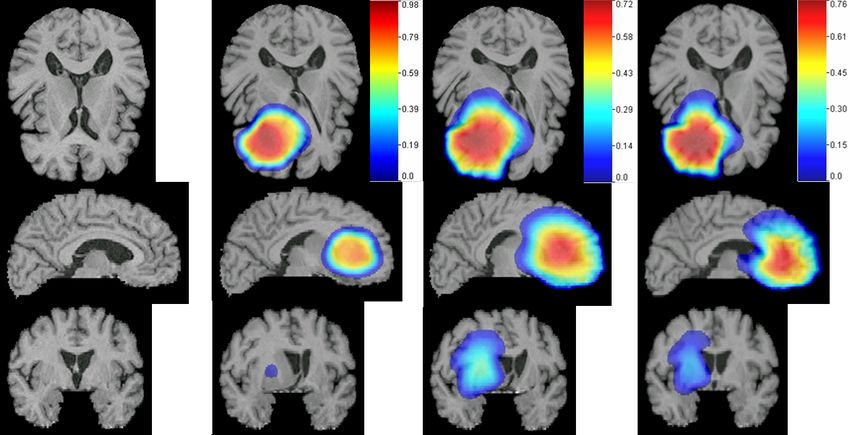
Fig. 3. Real brain tumor images, dog case DC1. Top row, from left to right: starting
scan, T1 MR gadolinium-enhanced; target scan, T1 MR gadolinium-enhanced; our
simulated tumor growth and mass-effect via the new optimized framework: tumor color
maps overlaid on the model-deformed image, with corresponding color bar attached;
simulated mass-effect via the simplified incremental pressure approach in [3], with
tumor mask highlighted in white. The new tumor growth model shows potential to
capture more information about the tumor compared to the pressure approach. Bottom
row : illustration of a few of the target landmarks (marked with crosses) used for the
model-constrained optimization in this case.
Finally, we are building non-uniform structured discretizations based on octree
data structures to further reduce computational cost and allow more accurate
approximations in regions of interest.
References
1. Mohamed, A., Davatzikos, C.: Finite element modeling of brain tumor mass-
effect from 3d medical images. In: Proceedings of Medical Image Computing and
Computer-Assisted Intervention, Palm Springs (2005)
2. Clatz, O., Sermesant, M., Bondiau, P.-Y., Delingette, H., Warfield, S.K., Ma-
landain, G., Ayache, N.: Realistic simulation of the 3d growth of brain tumors
in mr images coupling diffusion with mass effect. IEEE Trans on Med. Imaging 24,
1334–1346 (2005)
3. Hogea, C., Abraham, F., Biros, G., Davatzikos, C.: A framework for soft tissue
simulations with applications to modeling brain tumor mass-effect in 3d images.
In: Medical Image Computing and Computer-Assisted Intervention Workshop on
Biomechanics, Copenhagen (2006)
4. Hogea, C., Abraham, F., Biros, G., Davatzikos, C.: Fast solvers for soft tissue sim-
ulation with application to construction of brain tumor atlases (Technical report)
ms-cis-07-04, http://www.seas.upenn.edu/∼ biros/papers/brain06.pdf650 C. Hogea, C. Davatzikos, and G. Biros
5. Swanson, K.R., Alvord, E.C., Murray, J.D.: A quantitative model for differential
motility of gliomas in grey and white matter. Cell Proliferation 33, 317–329 (2000)
6. Tracqui, P., Mendjeli, M.: Modelling three-dimensional growth of brain tumors
from time series of scans. Mathematical Models and Methods in Applied Sciences 9,
581–598 (1999)
7. Habib, S., Molina-Paris, C., Deisboeck, T.: Complex dynamics of tumors: modling
an emerging brain tumor system with coupled reaction-diffusion equations. Physica
A: Statistical Mechanics and its Applications 327, 501–524 (2003)
8. Hogea, C.: Modeling Tumor Growth: a Computational Approach in a Continuum
Framework. PhD thesis, Binghamton University (2005)
9. Wasserman, R.M., Acharya, R.S., Sibata, C., Shin, K.H.: Patient-specific tu-
mor prognosis prediction via multimodality imaging. Proc. SPIE Int. Soc. Opt.
Eng. 2709 (1996)
10. Tyson, R., Stern, L.G., LeVeque, R.J.: Fractional step methods applied to a chemo-
taxis model. J. Math. Biol. 41, 455–475 (2000)
11. Verwer, J., Hundsdorfer, W., Blom, J.: Numerical time integration for air pollution
models. In: Report MAS-R9825, CWI Amsterdam (1991)
12. Kolda, T., et. al.: APPSPACK (2005), home page.
http://software.sandia.gov/appspack/version5.0
13. Gunzburger, M.: Perspectives in Flow Control and Optimization. SIAM (2002)You can also read