New V8 Engines Feature Dynamic Fuel Management
←
→
Page content transcription
If your browser does not render page correctly, please read the page content below
Mid-August 2018, Volume 20, No. 16
New V8 Engines Feature
Dynamic Fuel Management
The all-new 2019 Silverado 1500 and
Sierra 1500 offer two new V8 engines:
the 5.3L V8 (RPO L84) and the 6.2L V8 (RPO L87).
These new engines deliver the power demanded by truck owners — the 5.3L V8 has a
power output of 355 horsepower and 383 lb.-ft. of torque and the 6.2L V8 develops CONTENTS
420 horsepower and 460 lb.-ft. of torque — while optimizing fuel economy.
One of the enhancements to the ef-
ficiency of the new engines is the new New V8 Engines Feature Dynamic
Dynamic Fuel Management (DFM) Fuel Management . . . . . . . . . . . . . . . . . . . . 1
system, which is the successor to Ac-
tive Fuel Management (AFM). AFM CVT Transmission Fluid Degradation
alternated between 8 cylinder and 4 and Replacement. . . . . . . . . . . . . . . . . . . . . 3
cylinder modes, but DFM actively turns
Using the GE-52079 Coolant System
off any number of cylinders in a variety of
Fill Tool. . . . . . . . . . . . . . . . . . . . . . . . . . . . . 4
combinations, allowing the engine to run
on 17 different cylinder patterns. Inoperative Electric Parking Brake. . . . . . . . 5
DFM is powered by a sophisticated
Hard-to-Close Rear Door or
controller that continuously monitors
Rattle Sound. . . . . . . . . . . . . . . . . . . . . . . . 6
the vehicle’s accelerator pedal and
runs a complex sequence of calcula-
tions to determine how many cylinders
are required to meet the driver’s power Customer Care and Aftersales
continued on page 2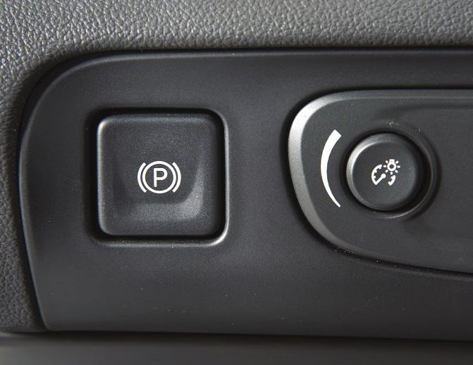
New V8 Engines Feature Dynamic Fuel Management
– continued from page 1
emand. The DFM controller can make this determination 80 times
d When operating conditions require a return to V8 mode, the ECM
per second. Switching between V8 and DFM modes is accomplished turns off the control circuits for the solenoids, allowing the solenoid
in less than 250 milliseconds, or within two revolutions of the crank- valves to close. With the solenoid valves closed, engine oil pressure
shaft, making the transition seamless and transparent to the driver. in the control ports is exhausted through the body of the solenoids
into the engine block lifter valley. The oil passages of the valve lifter
Valve Lifter Operation oil solenoid valves incorporate several bleeds in the oil passages to
purge any air trapped in the engine block.
Cylinder deactivation is accomplished by not allowing the intake and
exhaust valves to open on the selected cylinders by using special Valve Lifter Oil Solenoid Valve Operation
valve lifters. The deactivation lifters contain spring loaded locking
pins that connect the internal pin housing of the lifter to the outer DFM uses eight valve lifter oil solenoid valves (one for each cylin-
housing. der) that are mounted in the engine block valley under the engine
block valley cover. Each solenoid controls engine oil pressure to the
intake and exhaust valve lifters on the cylinders selected to deac-
tivate. Engine oil pressure is routed to the lifter oil gallery from an
internal oil passage on the rear of the cylinder block.
DFM system lifters and solenoids
DFM engine block valley cover
When cylinder deactivation is commanded, the ECM will determine
what cylinder is firing and begin deactivation on the next closest
deactivated cylinder in the firing order sequence. Although both When an oil control solenoid
intake and exhaust valve lifters are controlled by the same solenoid, valve is commanded open,
the intake and exhaust valves do not become deactivated at the pressurized oil forces the lifter
same time. Cylinder deactivation is timed so that the cylinder is on locking pins (E) inward. The
an intake event. pushrod (A) remains in a con-
stant position and does not
During an intake event, the intake cam lobe is pushing the valve travel upward and downward.
lifter upward to open the intake valve against the force of the valve The outer body of the lifter (C)
spring. The force exerted by the valve spring is acting on the side of moves upward and downward
the lifter locking pins, preventing them from moving until the intake independently from the pin
valve has closed. When the intake valve lifter reaches the base housing (D). The valve lifter
circle of the camshaft lobe, the valve spring force is reduced, allow- spring (B) retains tension on
ing the locking pins to move, deactivating the intake valve. the valve train components to
When cylinder deactivation is commanded on, the exhaust valve for eliminate valve train noise.
the deactivated cylinder is in the closed position, allowing the lock- With DFM, the engines are
ing pins on the valve lifter to move immediately and deactivate the able to better balance power
exhaust valve. needs with fuel efficiency.
When all enabling conditions are met for cylinder deactivation, During an industry-standard
the ECM will actuate the high and low control of each solenoid test schedule, the 2019
control circuit in firing order sequence, allowing current to flow Silverado 2WD with the 5.3L A. pushrod
through the solenoid windings. With the coil windings energized, V8 and DFM operated with B. valve lifter spring
the solenoid valve opens, redirecting engine oil pressure through fewer than eight active cylin- C. valve lifter body
the valve lifter oil solenoid valves into 16 separate vertical passages ders more than 60 percent of D. pin housing
the time, 9 percent more than E. lifter locking pin
in the engine lifter valley. The 16 vertical passages — two per cyl-
inder — are connected to the valve lifter bores of the cylinders to a comparably equipped 2018
be deactivated. model with AFM.
Thanks to Dave MacGillis and Sherman Dixon
2 Mid-August 2018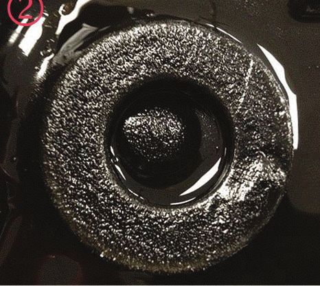
CVT Transmission Fluid Degradation and Replacement
Some Jatco CVTs (continuously variable ratio automatic trans- TIP: It’s normal for the transmission to remain in high range
missions) (RPOs M4M, MR8) available in the 2014-2019 Spark under medium to hard braking and may only make the high/low
may have a short duration shudder on launch from a stop or on range shift on acceleration after the braking maneuver.
acceleration from a low speed, such as when turning a corner. The
shudder is a momentary condition and may only occur under certain Drain and replace the fluid to reduce the shudder condition. Start
rates of braking and accelerating. the procedure by first removing the fluid pan and inspecting the
magnets for metal debris. It is normal to have some metallic
Degradation of the CVT transmission fluid may alter the friction build-up on the magnets. If the magnets show only normal magnetic
characteristics of the transmission and lead to shudder concerns sludge, reinstall the pan using a new gasket, if needed. Do not
during a shift from high or low range. replace the transmission if metal chips cannot be felt in the mag-
netic sludge. Refer to #PIP5548 for additional information.
Normal amount of debris in the fluid.
Cooler return port
Reinstall the fluid pan and fill the transmission with five quarts
(4.73 L) of ACDelco CVT fluid (P/N 19260800, U.S.; 19299096,
Canada). Filled with five quarts, the transmission will be over full.
Disconnect only the transmission cooler return line from the trans-
mission and route it into a suitable container. The cooler return line
connects at the lower port at the transmission.
Run the engine for 30 seconds and then check the amount of fluid in
the container. The flow rate should be approximately one quart per
10 seconds. It will take 3–4 quarts (2.8–3.8 L) to flush the torque
converter and discharge clean fluid from the return line. If neces-
sary, run the engine again, but for no more than 20 seconds.
Reinstall the cooler return line and add two quarts of CVT fluid to
the transmission. Adjust the fluid level following the instructions in
the appropriate Service Information.
After replacing the fluid, the shudder should be noticeably improved
within 100 miles (160 km). However, it may take up to 300 miles
(480 km) for the new fluid to fully saturate the clutch plates.
Thanks to Frank Jakubiec and Brady Jezewski
Abnormal amount of debris in the fluid.
Mid-August 2018 3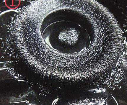
Using the GE-52079 Coolant System Fill Tool
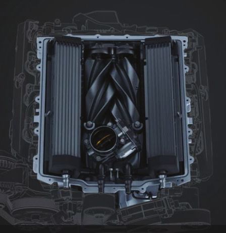
The supercharged 6.2L V8 engine (RPO as the method for adding coolant into the
LT5) in the 2019 Corvette ZR1 uses five GE-52079 Coolant System Fill Tool. The
charge air cooling radiators. Behind the GE-47716 Vac-N-Fill Tool should be filled
front fascia, there are three charge air cool- with the proper mixture of coolant and
ing radiators; one in the center and one in clean, drinkable water (refer to the appro-
each corner. There are two more within the priate Service Information procedure).
supercharger assembly. Two on-vehicle
electric pumps are used to pump coolant to After the system is initially filled using the
the driver-side port and the passenger-side Vac-N-Fill method, it is necessary to cycle
port of the supercharger. the auxiliary coolant pumps. The coolant
is circulated using the auxiliary coolant
The coolant is drained by disconnecting the pumps by commanding the pumps on using
hoses at the respective charge air cool- GE-52079 Coolant System Fill Tool
the GDS 2 diagnostic scan tool (be sure to
ing radiators. The coolant is filled via quick connect a battery charger). As the pumps
connect tee fittings at the inlet ports of the begin to circulate coolant, the GE-52079-10
supercharger. The LT5 charge air cooling adapter diverts a large quantity of cool-
system does not have a remote reservoir, ant into the GE-52079 clear reservoir. Air
surge tank, or drain plug. bubbles are released from the coolant and
exit at the top of the reservoir through the
loosened fill plug.
During the de-aerating procedure, if cool-
ant flow has stopped, it is because the
charge air cooler coolant pumps have shut
off. Both coolant pumps will shut off if they
start to draw air (sensed by pump RPM). If
this occurs, repeat the Vac-N-Fill procedure
to pull the system into a vacuum to remove
air, followed by allowing the pumps to push
GE-52079-10 Coolant System Fill Adapter
coolant into the GE-52079 reservoir.
fects on vehicle performance (i.e., loss of Coolant will continue to enter the GE-
horsepower). 52079 reservoir and de-aerate the vehicle’s
cooling system. The measurement gauge
Filling the System on the side of the GE-52079 reservoir can
The GE 52079-10 adapter plugs into the be used to monitor the decreasing level
coolant system quick connect fill port tee. of the coolant inside the reservoir. When
LT5 supercharger It does not matter which of the fill port the system has stabilized at a specific
tees are used; however, the arrow on the level within
adaptor must point out and away from the the reservoir
Any time that the supercharger’s cooling engine. and no more
system is serviced, it must be properly air bubbles
drained and filled using the following special are visible,
tools: the system is
considered full.
• GE-26568 Coolant and Battery Fluid
Tester After the
system is
• GE-47716 Vac-N-Fill Coolant Refill Tool
considered
• GE-52079 Coolant System Fill Tool full, shut down
• GE-52079-10 Coolant System Fill Tool the pumps
Adapter and close the
valves on the
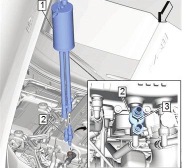
The GE-52079 Coolant System Fill Tool GE-52079 Complete de-aerated coolant.
and GE-52079-10 Coolant System Fill Tool hoses to pre- System FULL
Adapter are required to fill the charge air pare the tool
cooling system on the Corvette ZR1 (LT5) to be disconnected from the vehicle. The
and Z06 (LT4). The Vac-N-Fill machine shut-off valves on each hose and on the
must be used in conjunction with these tool reservoir help avoid leaking any resid-
tools. 1. GE-52079 Coolant System Fill Tool ual coolant remaining in the reservoir after
2. GE-52079-10 Coolant System Fill Tool Adapter service is completed.
The GE-52079 Coolant System Fill Tool is
3. Arrow on adapter must point out from engine
designed to purge all air from the system Thanks to Chuck Berecz, Tracy Lucas,
after service, which will achieve a complete Austin Leopold and Christopher
fill. This is very important because any air The GE-47716 Vac-N-Fill Tool is required Semanisin
left in the system will have detrimental ef- to pull the system into a vacuum and serves
4 Mid-August 2018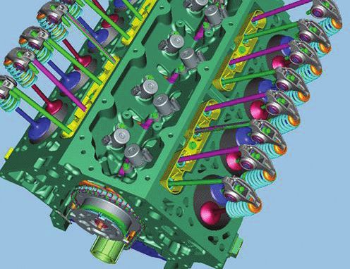
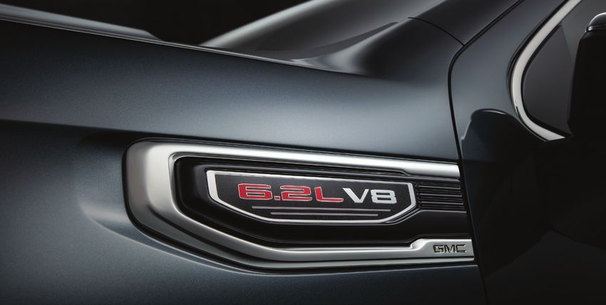
Inoperative Electric Parking Brake
The electric parking brake (EPB) may be inoperative on some 2018 An inoperative electric parking brake may be due to several differ-
Acadia, Enclave, Traverse and XT5 models. The Service Park Brake ent conditions.
warning lamp also may be illuminated.
Water Leak
To apply the parking brake on Acadia, Enclave and XT5 models,
press the EPB button on the left side of the instrument panel. To If the electric parking brake is inoperative and DTC C028F (Left
release the parking brake, the ignition must be on. Press the brake Park Brake Actuator Circuit) or DTC C1586 (Right Park Brake
pedal first and then press the EPB button. Actuator Circuit) is set in the Electronic Brake Control Module
(EBCM), check for water leaking into the rear actuator, causing a
short to ground.
If DTCs
C028F 04
(short to
ground) and/
or C1586
04 (short to
ground) are
set, verify
which EPB
actuator set
the DTC and
replace the
actuator fol-
lowing the
appropriate
Service Infor-
mation.
The brake
EPB button actuator
has a newly
designed 1. Old cover design
To apply the parking brake on Traverse models, pull the EPB switch
cover. When 2. New cover design
on the center console. To release the parking brake, with the igni-
replacing
tion on, press the brake pedal first and then press the EPB switch.
the actuator, verify that it has the updated cover, not the old cover
design.
EBCM Software
If the electric parking brake is inoperative and there has been a
previous repair to the brake actuator, the inoperative condition may
be caused by a software anomaly in the EBCM.
If there are not any DTCs set and the brake actuators have
previously been replaced, program the K17 EBCM with the latest
calibration available using the Service Programming System (SPS).
Weak Battery
If the electric parking brake is inoperative and DTC C1587 0B (Left
Park Brake Actuator – Software Sensitivity or C1588 0B (Right
Park Brake Actuator – Software Sensitivity) is set in the EBCM,
the vehicle may have a weak battery, which affects the operation of
the software. If these DTCs are set, program the K17 EBCM with
the latest calibration available using SPS.
Thanks to Tom Burlingame
EPB actuator
Mid-August 2018 5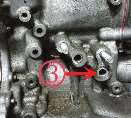
Hard-to-Close Rear Door or
Rattle Sound
The rear door
may be hard
GM TechLink is published for all to close on
GM retail technicians and service some 2015-
2017 Colorado
consultants to provide timely and Canyon
information to help increase know extended cab
ledge about GM products and models. In ad-
improve the performance of the dition, there
may be a rattle
service department. sound from
Publisher: the lower rear
door area and a
John Meade
Rear Door Ajar
GM Customer Care and Aftersales
message may
Editor: be displayed
Lisa G. Scott on the Driver
GM Customer Care and Aftersales Information
Center (DIC). Lower rear striker
Technical Editor:
If these condi-
Mark Spencer tions are found,
/ mspencer@gpstrategies.com the rear door
Production Manager: lower striker
may be out of
Marie Meredith position.
Creative Design: To correct
5by5 Design LLC these condi-
/ dkelly@5by5dzign.com tions, first
verify which
Fax number: rear door is
3 1-248-729-4704 causing the
Write to: conditions and
* TechLink verify the front
door is ad-
PO Box 500
justed properly.
Troy, MI 48007-0500
Adjusting the
GM TechLink on the Web: rear door lower
: GM GlobalConnect striker will ad-
dress a hard to : Loosen the two bolts to adjust the striker.
General Motors service tips are intended close door con-
for use by professional technicians, not dition, but additional diagnosis will be necessary if the doors are misaligned.
a “do-it-yourselfer.” They are written to
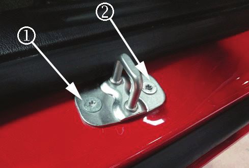
inform those technicians of conditions Next, loosen the two bolts on the lower rear striker and adjust the striker. The striker
that may occur on some vehicles, or to can be adjusted by shutting the door repeatedly or by tapping the striker with a mal-
provideinformation that could assist in let after the bolts have been loosened. The anchor plate allows +/– 3.0 mm fore/aft
the proper service of a vehicle. Properly and cross-car adjustment.
trained technicians have the equipment, When adjusting the striker, use care to not scratch the painted area surrounding the
tools, safety instructions and know-how
striker.
to do a job properly and safely. If a
condition is described, do not assume After making the necessary adjustments, tighten the two bolts on the lower rear
that the information applies to your striker to 24 Nm (18 lb.-ft.). Verify that the door properly closes fully.
vehicle or that your vehicle will have that
condition. See a General Motors dealer Thanks to Charles Hensley
servicing your brand of General Motors
vehicle for information on whether your
vehicle may benefit from the information.
Inclusion in this publication is not
necessarily an endorsement of the
individual or the company.
Copyright© 2018 General Motors
All rights reserved.
6 Mid-August 2018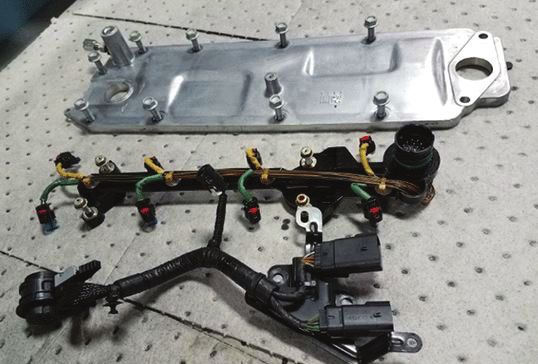
You can also read