Towards Developing a Teleoperation System for a Disaster Response Robot - SHS Web of Conferences
←
→
Page content transcription
If your browser does not render page correctly, please read the page content below
SHS Web of Conferences 102, 04005 (2021)                                                             https://doi.org/10.1051/shsconf/202110204005
ETLTC2021

      Towards Developing a Teleoperation System for a Disaster Response Robot

      Udaka A. Manawadu1 , Hiroaki Ogawa2 , Keito Shishiki2 , Yuki Funayama1 , Hiroto Sasaki2 , Takuma Suzuki2 , and Keitaro
      Naruse2∗
      1
          Graduate School of Computer Science and Engineering, University of Aizu, Aizu-Wakamatsu, Japan.
      2
          Department of Computer Science and Engineering, University of Aizu, Aizu-Wakamatsu, Japan.

                    Abstract. Standard Disaster Robotics Challenge of World Robot Summit (WRS) aims to test the ability of
                    robots that can be used as disaster response robots. Robot Engineering Lab of the University of Aizu is devel-
                    oping a robotic system to address challenges in the WRS. The competition has five stages, and the teleoperation
                    robotic system had to be developed to satisfy the requirements of each challenge. REL uses a disaster-response
                    robot called Giraffe, which has the capability of traveling in hard terrain. Open Robot Technology Middleware
                    uses to integrate all of the subsystems inside the robot. Each subsystem has different tasks that process video
                    data, RGB depth data, Point Cloud Data, sensor data and, feedback data. The Robotic system includes 6 cam-
                    eras and NDI Software Developer Kit used to transmit and view video streams remotely. The video stream
                    from each camera can be viewed separately, and it gives wider control over the robot for the operator. The
                    teleoperation robotic system was tested during a robot demonstration held in Fukushima Robot Test Field, and
                    results were analyzed according to the WRS 2018 competition guidelines. The results were at an acceptable
                    level.

      1 Introduction                                                          and how this development helps to collaborate between
                                                                              academia and industry.
      In this paper, we are going to describe how the Robot En-
      gineering Lab of the University of Aizu (REL) developed                 2 Methodology
      a Teleoperation (Tele-Op) System for a disaster-response
      robot to face the Standard Disaster Robotics Challenge of               Since the competition tasks varied in a wide range, team
      World Robot Summit (WRS). The aims of the WRS are                       management and software development throughout a large
      accelerating the social implementation, and research and                team was a challenging procedure. Usually, about 10 stu-
      development of robots in real life, social and industrial               dents in REL were involved in software development and
      fields [1]. The categories of WRS were created based on                 carrying out the robot’s operations. When selecting the
      the incidents that happened after the 2011 Tōhoku earth-               hardware for the robotic system REL, consider the se-
      quake and tsunami. After the earthquake of 2011, a large-               lected hardware’s accuracy and availability. For software
      scale nuclear accident occurred in Fukushima Daiichi Nu-                development, REL considered reliability and high respon-
      clear Power Plant. At the nuclear power plant, most of the              siveness when building software for the robotic system.
      restoration work was being carried out manually at that
      time. Therefore the nonexistence of robotic systems that
                                                                              2.1 Managing Teams
      could address such a situation became an issue [2]. Devel-
      oping robotics systems that can be used for such systems                Firstly, the students in REL were divided into two main
      has become a timely manner.                                             teams, a team that was dealing with actual machines
          The teams participating in WRS should prepare their                 (STM) and a team that was dealing with simulation envi-
      system for five stages: Negotiate, Catwalk, Meter/Valve,                ronment (SIM). Each team was working towards different
      L-Shaped Obstacle on Uneven Ground, and Large-area In-                  tasks. Since the tournament is held at least once a year,
      spection. Figure 1 shows each of the tasks given in the                 students worked together to improve robots and software
      challenge [1].                                                          for the challenge. Each of the teams was led by a final year
          Participating in such competition is difficult, espe-               undergraduate (B4) or a student studying for the master’s
      cially managing a large team and developing software in a               (M1), and the rest of the students (1st , 2nd and 3rd year un-
      distributed environment. This paper focuses on describ-                 dergraduate students) were in charge of robot operators for
      ing how we manage our team for the WRS, hardware                        each task.
      and software selection for developing the robotics system,                  If B4 and M1 students found research themes and top-
                                                                              ics related to the tasks in WRS, they continuously updated
           ∗ e-mail: naruse@u-aizu.ac.jp                                      the robot software by adding new features according to

© The Authors, published by EDP Sciences. This is an open access article distributed under the terms of the Creative Commons Attribution License 4.0
(http://creativecommons.org/licenses/by/4.0/).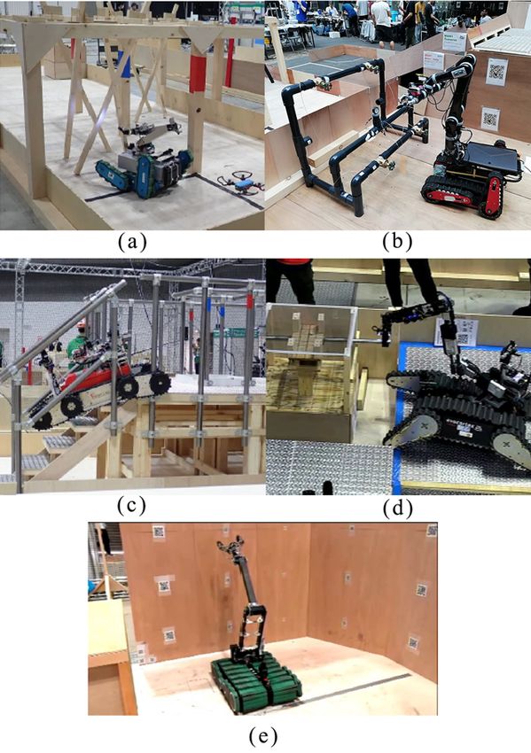
SHS Web of Conferences 102, 04005 (2021)                                                               https://doi.org/10.1051/shsconf/202110204005
ETLTC2021

                                                                                                                  Figure 2. Usually, students in
                                                                                                                  REL go through the learning
                                                                                                                  process from practicing the
                                                                                                                  robot to adding improvements
                                                                                                                  to the robotic software.

                                                                                 of themselves when handling the robot since the Giraffe
                                                                                 (figure 3) weighs about 80 kilograms, and it is required to
                                                                                 wear helmet and safety shoes when operating the robot.
                                                                                 The team also held seminars every year to practice safely.

                                                                                 2.2 The Robot

                                                                                 In REL, we are using a disaster-response robot called ‘Gi-
                                                                                 raffe’ as the crawler. Giraffe was made by Aizuk Pvt.
                                                                                 Ltd, with collaboration with REL. Giraffe is a crawler-type
                                                                                 robot that has two main crawlers and four sub crawlers.
                                                                                 Four sub crawlers work independently, and it enables
                                                                                 to run through rough terrain, and the flexibility of the
      Figure 1. Each of the tasks given in the WRS. In the brackets,             crawlers made it easy to face challenges of WRS (Figure
      the task code is given. (a) Negotiate (Task MAN1 ): stage to               3) [3]. Apart from that, it consists of an inbuilt PC that
      test whether the robot can pass through a narrow space well. (b)
                                                                                 runs in Linux Operating System.
      Meter / Valve (Task DEX1): A stage that reads the meter’s value
      by turning the valve or lever. (c) Catwalk (Task MOB1): A stage
      that climbs stairs and is tested for stability on unstable scaffold-
      ing. (d) L-shaped Debris on Uneven Ground (Task DEX2): a
      comprehensive stage, such as traversing the rattling scaffolding
      and grasping and operating the pipe with the arm. (e) Large Area
      Inspection (Task EXP1): A stage that reads the QR code affixed
      to the wall, photographs the wall, and creates a three-dimensional
      map of the wall [1]

                                      .
      their research. While operating the robot, the junior stu-
      dents would gradually learn the robotic system and deepen
      their understanding of the disaster response robotic field.
      Figure 2 shows the learning cycle of the student who par-
      ticipated in the challenge.
                                                                                 Figure 3. Giraffe robot doing “Catwalk” task in the 4th Univer-
           The team usually practiced the robot in an environment
                                                                                 sity of Aizu Robot Symposium in 2019 [4].
      that imitated the previous versions of WRS challenges.
      This environment allows students to find improvements to                       The Giraffe was modified to connect an arm externally
      the robot and practice with higher accuracy. By practicing                 and connect another PC externally. KINOVA JACO arm
      the operation daily, it is possible to understand the perfor-              with 6 degrees of freedom Curved Wrist is used as the
      mance lacking areas of the robot and shape-up the con-                     external arm of the robot. The JACO arm’s flexibility is
      trolling accurately. The issues that come when practicing                  heavily useful for tasks like DEX1 and DEX2 in the com-
      were divided into long-term, medium-term, and short-term                   petition (In figure 1). Jaco arms are usually used in Ser-
      issues, and they were solved according to the difficulties.                vice Robotics, and Assistive Robotics due to their flexibil-
      There are two ways to get a good score in the competition.                 ity and finger capability [5]. As in figure 4, a rubber was
           One is to improve the ability of the robot, and the other             put on the robot finger to give an extra grip for holding or
      is to improve the skill of operation of the operator. In the               turning an object.
      future, the goal is to improve the capabilities of robots so                   Apart from the arm, 6 cameras were installed in differ-
      that anyone can use them easily, but considering the com-                  ent directions enabling total control of the robot remotely.
      petition, it is also important to get good results by covering             There are two front and back cameras and two fish-eye
      them with operations. The team also considered the safety                  360° cameras to inspect the surroundings more widely.

                                                                             2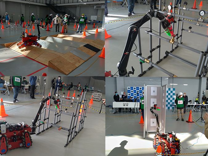
SHS Web of Conferences 102, 04005 (2021)                                                       https://doi.org/10.1051/shsconf/202110204005
ETLTC2021

      Figure 4. The Robotic system created by REL consisting of all the hardware arrangements, and the Tele-Op side consists of all the
      controlling components.

      The robot was mainly controlled by using those four cam-           is developed by an SDK called NDI. OpenRTM-aist is
      eras. The other two cameras were placed on the Jaco arm            a distributed component middleware for robot technolo-
      (figure 4). One is a web camera for the meter reading task,        gies developed and distributed by the National Institute of
      and the other is Intel RealSence Depth Camera D435 to              Advanced Industrial Science and Technology, Japan [7].
      measure and map depth in 3-D space in the Large Area               The team used OpenRTM-aist instead of Robot Operat-
      Inspection task. Ease of use, accuracy, small size, and            ing System (ROS) due to the high responsiveness of the
      availability of the Software Development Kit (SDK), were           OpenRTM-aist than ROS systems. In OpenRTM-aist, the
      considered when choosing RealSence D435 [6].                       function elements in the system are called RT components
          The robotic system is integrated with three Personal           (RTC). By connecting components, it is easy to configure
      Computers (PC) in a single network. All PCs were run in            a system that applies robotic technology. For example, we
      a Linux environment.                                               can issue commands from a controller to move the robot
      • Crawler PC: The PC inside the Giraffe that controls              or check the robot’s status at a glance on a PC. This can
        crawlers (A less powerful PC).                                   be accomplished by RTC communicating with each other.
                                                                         One can explicitly check the connectivity of RTC. By con-
      • Arm PC: The PC that was put on the Giraffe (figure 4)            necting the desired RT components, one can reflect the be-
        to handle the Jaco arm, six cameras, and then transfer           havior of the robot. Figure 5 shows the OpenRTM-aist
        the control signal to the Tele-op PC.                            system diagram of our system.
      • Tele-Op PC: The 3rd PC (laptop) for the operator that
        connects the controller and shows the video stream of
        the camera.
           On the Tele-op side, the operator operates the robot
      remotely using the controller connected to the laptop.
      We need to move the robot remotely in the competition.
      Therefore, the operator needs to grasp the situation of the
      robot while watching the images of the cameras attached
      to the robot and perform various tasks. Either WiFi or
      network wires can be used as the communication method
      between the robot and the Tele-op laptop. In the compe-
      tition, we are using network wires as the communication
      method due to the high stability of the system. We called
      the whole robotic system in figure 4 as "Spider2020".              Figure 5. The OpenRTM-aist system diagram that used for the
                                                                         robotic system.
      2.3 Software Development
                                                                             According to the diagram, it is easy to dis-
      The control and software integration of the robot is               tinguish how the signal flows through the system.
      managed by the Open Robot Technology Middleware                    RTC_DS4_Controller0 is a component that gives the con-
      (OpenRTM-aist), and the camera viewer in Tele-op side              trolling signals to RTC_Spider2020_Motion0 component

                                                                     3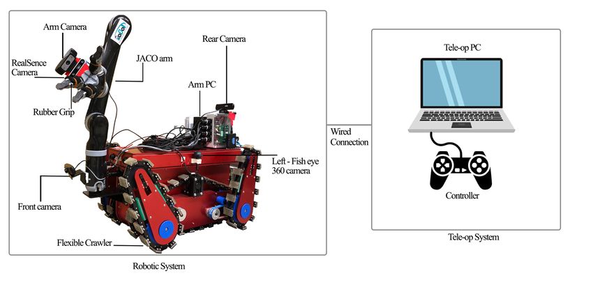
SHS Web of Conferences 102, 04005 (2021) https://doi.org/10.1051/shsconf/202110204005
ETLTC2021
controls arm and motion controls then signals pass to OpenRTM-aist is colored by blue, OpenRTM-aist compo-
RTC_Spider2020_Crawler0 and RTC_Spider2020_Jaco0, nents are colored by light blue, and the library associated
which are the components of Spider2020’s motions with NDI is colored by light yellow.
and Arm motions in order. Task MAN1 and Task
MOB1 (figure 1) Jaco arm was not needed, and 3 Results
RTC_Spider2020_Jaco0 was disabled for those tasks.
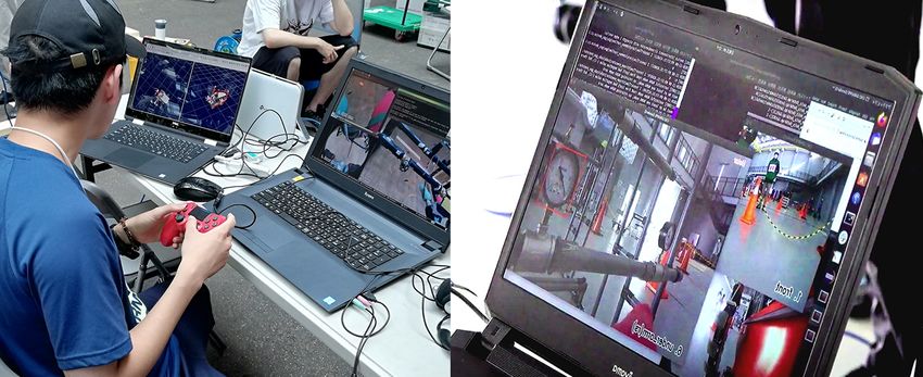
Figure 6. Left: Using NDI, operator operating Spider2020.
Right: Multiple screens that show different camera views (One
camera view shows meter value while other camera view show
surroundings).
NDI, which stands for Network Device Interface, is an
SDK that can transmit a video stream via a network. By Figure 8. Pictures were taken at robot demonstration at
introducing NDI, we could obtain live video data from the Fukushima Robot Test Field.
robot’s camera to the Tele-Op laptop, which is needed for
remote control. We have developed a software that allows
The results for Meter/Valve (Task DEX1) and Large Area
the operator to select the information of a camera to be ac-
Inspection (Task EXP1) is shown in Figure 9.
quired from multiple cameras by using this SDK to realize
a system that allows the operator to easily understand the
situation around the robot (Figure 6). Multiple processes
are running simultaneously, and it is possible to get the in-
formation obtained by all the cameras in real-time. Each
camera is assigned a shortcut key on the keyboard, and the
operator can select a camera at will.
We also used Realsence SDK and OpenCV to com-
pete in competitions where we survey large areas because
we can store data about our surroundings. The informa-
tion around the robot can be acquired as a point cloud of
data. In this way, RealSense has the ability to recognize
information about the object in front of it more clearly.
Teleop PC
RTC_Controller RTC_Motion QR_decode NDI_Receiver
OpenRTM-aist Zbar OpenCV NDI
OS (Ubuntu)
PS4_Controller
Arm PC Figure 9. (a) image shows results for Meter/Valve; Deep learn-
RTC_Jaco PCD_Merge QR_decode OpenCV PCD_Save NDI_Sender
ing was used for identified meter value automatically [8]. (b)
OpenRTM-aist PCL ZXing Jaco RS2 NDI
image shows current results for Large Area Inspection.
OS (Ubuntu)
Arm Realsense Web cam
Crawler PC
RTC_Crawler
Throughout the competition, we are finding issues and
OpenRTM-aist making improvements, and updating the software daily.
OS (Ubuntu) We believe that this will lead to our own researches, the
Motor
promotion of the robotics industry, and contributions to
society and reconstruction.
Figure 7. Summarized Spider2020 system overview.
4 Conclusion
Finally, the whole system can be summarized in the This paper describes how REL managed to build the Spi-
following figure 7. Hardware devices are colored by red, der2020 robotic system. Flexible crawler and arm and
4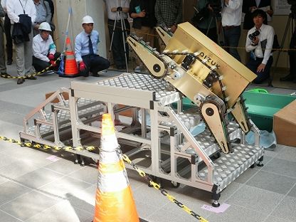
SHS Web of Conferences 102, 04005 (2021)                                                    https://doi.org/10.1051/shsconf/202110204005
ETLTC2021

      camera sensors that cover a wide area make Spider2020 a           [3] N. Baba, Disaster Response Robots ‘Giraffe’ Devel-
      complete disaster-response robot. However, hardware im-               oped by the Members of Fukushima Consortium of
      provements are not enough to use a robotic system in a dis-           Robotics Research for Decommissioning and Disaster
      aster, and software improvements should be made simul-                Response, in 4th International Forum on the decom-
      taneously. Since the robot’s task range has a wide variety,           missioning on the Fukushima Daiichi Nuclear Power
      many subsystems are running inside the system. Dividing               Station (2019), p. 10
      each task for different teams improved the efficiency of          [4] The 4th university of aizu robotics symposium,
      students since each team needed to improve background                 https://www.u-aizu.ac.jp/en/information/
      knowledge of a specific narrow research area. Identify-               post-20171151.html
      ing issues, categorizing them, and continuously improving         [5] A. Campeau-Lecours, H. Lamontagne, S. Latour,
      the system make a solid foundation to participate in events           P. Fauteux, V. Maheu, F. Boucher, C. Deguire, L.J.C.
      such as WRS.                                                          L’Ecuyer, in Rapid Automation: Concepts, Method-
                                                                            ologies, Tools, and Applications (IGI Global, 2019),
                                                                            pp. 693–719
      References
                                                                        [6] A. Grunnet-Jepsen, J.N. Sweetser, P. Winer, A. Tak-
      [1] T. Kimura, M. Okugawa, K. Oogane, Y. Ohtsubo,                     agi, J. Woodfill, Intel Support, Interl Corporation:
          M. Shimizu, T. Takahashi, S. Tadokoro, Competi-                   Santa Clara, CA, USA (2018)
          tion task development for response robot innovation           [7] N. Ando, T. Suehiro, K. Kitagaki, T. Kotoku,
          in World Robot Summit, in 2017 IEEE International                 Woo-Keun Yoon, RT-middleware: distributed com-
          Symposium on Safety, Security and Rescue Robotics                 ponent middleware for RT (robot technology), in
          (SSRR) (2017), pp. 129–130                                        2005 IEEE/RSJ International Conference on Intelli-
      [2] K. Nagatani, S. Kiribayashi, Y. Okada, K. Otake,                  gent Robots and Systems (2005), pp. 3933–3938
          K. Yoshida, S. Tadokoro, T. Nishimura, T. Yoshida,            [8] Y. Funayama, K. Nakamura, K. Tohashi, T. Mat-
          E. Koyanagi, M. Fukushima et al., Journal of Field                sumoto, A. Sato, S. Kobayashi, Y. Watanobe, Artifi-
          Robotics 30, 44 (2013)                                            cial Life and Robotics pp. 1–11 (2020)

                                                                    5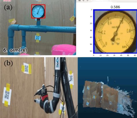
You can also read