Combining AR Markers with Various Kinds of Markers to Enhance User Interactions - Shengyu Fang
←
→
Page content transcription
If your browser does not render page correctly, please read the page content below
Combining AR Markers with Various Kinds of
    Markers to Enhance User Interactions

                       Shengyu Fang

                         44181041-7
                      Master of Engineering

                   Supervisor: Prof. Jiro Tanaka
  Graduate School of Information, Production and Systems Waseda
                            University

                         February 2020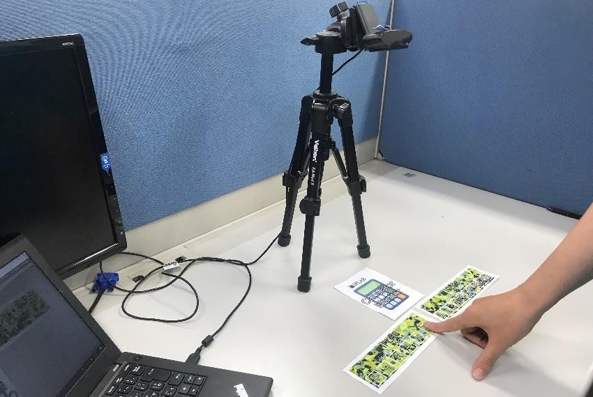
Abstract

Nowadays, the augmented reality technology is gradually appearing into people's view.

The numerous augmented reality applications have been used in the people’s daily life of

different kinds and disseminated all over the world. Marker-based AR system is one of

the most popular AR systems and many kinds of AR markers are used. They all use visual

marker-based systems for motion tracking and pose estimation but always independent

and no connection. Users cannot do some interaction or control the AR contents by

combing multiple markers as they desire. The user experience is not enough in multiple

markers field.

In this research, we proposed an augmented reality system which can create new

interactions between users and markers by combining multiple markers, hidden markers

and auxiliary markers. The system will detect multiple markers at the same time and

process them in a certain order with 2-dimension layout in one camera view. The system

also can detect a kind of controller marker called hidden marker, which can support users

put their finger on the button area to input commands. And the auxiliary markers always

perform as a token or key to get specific or decrypted information. This kind of marker

can help user to protect some unpublic AR contents in some cases. In this research, we

also give some applications based our new system.

Keywords: Augmented reality, Multiple marker, Hidden marker, Auxiliary marker
Acknowledgement

I would like to acknowledge my sincere gratitude to my supervisor, Professor Jiro Tanaka,

who made this work possible. His friendly guidance and expert advice have been

invaluable throughout all stages of writing this thesis. The door to his office was always

open whenever I ran into a trouble spot or had a question about my research or writing.

It is my great honor to have the opportunity to do research in IPLAB and to be a student

of Professor Jiro Tanaka.

I would also wish to express my gratitude to all members from IPLAB for extended

discussions and valuable suggestions which have contributed greatly to the improvement

of the thesis.

Special thanks are due to my parents, for their continuous support and understanding.

This thesis has been written during my stay at the WASEDA University. I would like to

thank the IPS for providing excellent working conditions.
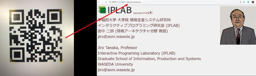
Table of Contents
Chapter 1 .......................................................................................................................... 1
Introduction ...................................................................................................................... 1
   1.1 Introduction ............................................................................................................ 1
   1.2 Organization of the thesis ....................................................................................... 2
Chapter2 ........................................................................................................................... 3
Background and related work ........................................................................................... 3
   2.1 Augmented Realty .................................................................................................. 3
       2.1.1 Definition ......................................................................................................... 3
       2.1.2 Marker-based Augmented Reality System ...................................................... 3
   2.2 Visual Markers ........................................................................................................ 4
Chapter3 ......................................................................................................................... 10
Research Goal and Approach ......................................................................................... 10
   3.1 Problem................................................................................................................. 10
   3.2 Goal .......................................................................................................................11
   3.3 Approach ................................................................................................................11
Chapter4 ......................................................................................................................... 12
System Design ................................................................................................................ 12
   4.1 Multiple Markers Recognition ............................................................................. 12
       4.1.1 Framework ..................................................................................................... 12
       4.1.2 Example of Application: Multiple markers combination .............................. 16
   4.2 Hidden markers recognition ................................................................................. 20
       4.2.1 Framework ..................................................................................................... 20
       4.2.2 Example of Application: AR Calculator ........................................................ 23
       4.2.3 Example of Application: AR Piano ............................................................... 27
   4.3 Auxiliary Marker .................................................................................................. 29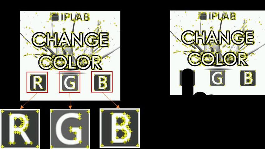
4.3.1 Personalization .............................................................................................. 29
       4.3.2 Encryption/Decryption .................................................................................. 31
Chapter5 ......................................................................................................................... 33
System Implementation .................................................................................................. 33
   5.1 Develop Environment ........................................................................................... 33
   5.2 System Hardware.................................................................................................. 34
   5.3 Project Scene ........................................................................................................ 35
   5.4 3D Virtual Content Modeling ............................................................................... 36
       5.4.1 Modeling in 3DMAX .................................................................................... 36
       5.4.2 Modeling in Unity3D..................................................................................... 37
   5.5 Multiple recognition ............................................................................................. 41
       5.5.1 Vuforia ........................................................................................................... 41
       5.5.2 AR toolkit ...................................................................................................... 46
       5.5.3 QR code ......................................................................................................... 48
       5.5.4 Marker measuring .......................................................................................... 49
   5.6 Hidden marker design........................................................................................... 51
Chapter6 ......................................................................................................................... 56
Conclusion ...................................................................................................................... 56
   6.1 Summary............................................................................................................... 56
   6.2 Future Work .......................................................................................................... 58
       Multiple Platform ................................................................................................... 58
       New Markers .......................................................................................................... 58
Reference ........................................................................................................................ 59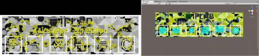
List of figures
Figure 1 Image target marker shows the AR content by Vuforia. .................................... 5
Figure 2 The visual marker of AR toolkit......................................................................... 6
Figure 3 An UPC-A barcode symbol. ............................................................................... 7
Figure 4 QR code for the URL of the IPLAB home page. ............................................... 8
Figure 5 Independent AR contents above the maker. ..................................................... 10
Figure 6 Scanning QR code by smartphone. .................................................................. 13
Figure 7 ATK marker showing AR contents. .................................................................. 14
Figure 8 Image target marker showing AR contents. ..................................................... 14
Figure 9 Multiple recognition. ........................................................................................ 15
Figure 10 Measuring the marker’s position. ................................................................... 16
Figure 11 Making programs by lining up command cards. ............................................ 17
Figure 12 The result will be shown by AR. .................................................................... 17
Figure 13 Different usage of markers. ............................................................................ 18
Figure 14 Output result by AR. ...................................................................................... 18
Figure 15 Star rating of markers in Vuforia database ..................................................... 21
Figure 16 Features recognition. ...................................................................................... 21
Figure 17 Hidden marker’s button area. ......................................................................... 22
Figure 18 Monitor marker. ............................................................................................. 23
Figure 19 Calculator 3D model. ..................................................................................... 23
Figure 20 Hidden marker. ............................................................................................... 24
Figure 21 Combine three markers. ................................................................................. 25
Figure 22 Re-design the number input marker. .............................................................. 25
Figure 23 Recognize the top button area user pressed marker. ...................................... 26
Figure 24 Input number by 2-dimensions buttons layout marker. .................................. 26
Figure 25 AR piano marker and phonic.......................................................................... 27
Figure 26 Multiple touch. ............................................................................................... 28
Figure 27 Two kinds of personal auxiliary marker and information. ............................. 29
Figure 28 Get customized information from the AR marker. ......................................... 30
Figure 29 Encrypted AR mail. ........................................................................................ 31
Figure 30 Unity3D, Vuforia, AR Toolkit. ....................................................................... 33
Figure 31 PC. .................................................................................................................. 34
Figure 32 Web camera. ................................................................................................... 34
Figure 33 Different scenes. ............................................................................................. 35
Figure 34 Elements in the scene. .................................................................................... 35
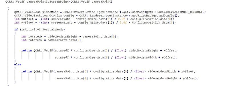
Figure 35 Building the outline. ....................................................................................... 36
Figure 36 Adding buttons. .............................................................................................. 36
Figure 37 The panel of UI. ............................................................................................. 37
Figure 38 Rect transform. ............................................................................................... 38
Figure 39 Text edit panel. ............................................................................................... 38
Figure 40 No Permission UI. .......................................................................................... 39
Figure 41 The AR invitation card in detail. .................................................................... 39
Figure 42 The AR personalization card for Nakamura. .................................................. 40
Figure 43 The AR personalization card for Nowa. ......................................................... 40
Figure 44 Getting the license key from Vuforia. ............................................................ 41
Figure 45 The image target markers database. ............................................................... 42
Figure 46 Image target marker ‘s information in detail.................................................. 42
Figure 47 Import the database. ....................................................................................... 43
Figure 48 Active the Vuforia. ......................................................................................... 43
Figure 49 Input the license key. ...................................................................................... 44
Figure 50 Change the camera. ........................................................................................ 45
Figure 51 Add image target marker. ............................................................................... 45
Figure 52 Register the AR content above the marker. .................................................... 46
Figure 53 Generating the AR toolkit marker by genTexData.exe. ................................. 47
Figure 54 Setting the marker. ......................................................................................... 47
Figure 55 Register the AR content. ................................................................................ 47
Figure 56 QR code reader script. .................................................................................... 48
Figure 57 QR code render script..................................................................................... 48
Figure 58 Scan the QR code and access to IPLAB home page. ..................................... 49
Figure 59 Change the world center mode to camera. ..................................................... 49
Figure 60 Take the camera space point and transform it into screen space. ................... 50
Figure 61 Feature points and button area. ...................................................................... 51
Figure 62 Define the area. .............................................................................................. 51
Figure 63 Transform the button area. ............................................................................. 52
Figure 64 Change the sensitivities. ................................................................................. 52
Figure 65 Operation input. ............................................................................................. 53
Figure 66 Number input. ................................................................................................ 54
Figure 67 Connect the information to AR monitor. ........................................................ 55
Chapter 1

Introduction
1.1 Introduction
Augmented Reality (AR) brings digital information and virtual objects into the physical

space [1]. Nowadays, numerous augmented reality applications have been used in the

people’s daily life of different kinds and disseminated all over the world. There are three

types of augmented reality: marker-based, marker-less and location-based. The marker-

based AR is the best-known type which uses cameras and visual cues.

Recently, with the development of marker-based AR system [3], a large number of visual

markers appear. And just only using single AR marker sometimes cannot meet needs of

users.

In this study, we survey the visual markers in current marker-based AR system and

compare their advantage and disadvantage. Then propose the framework of new marker-

based AR system which can combine multiple markers and using some other additional

markers to make the traditional marker-based AR system more attractive and effective.

                                            1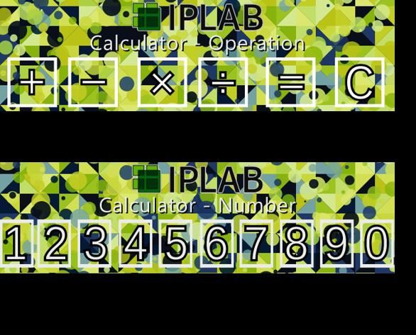
1.2 Organization of the thesis
The rest of the thesis is organized as follows: Chapter 2 introduces the background of the

thesis, survey of the current visual markers and also related work. Chapter 3 will tell the

research goal and the approach. Chapter 4 is the system design part, where the design

concept and ideas will be introduced, and the mechanism and algorithm design will also

be told. Chapter 5 will be the system implementation part where the detailed environment

and implementation will be talked. Chapter 6 will be the conclusion and future work part,

where we will conclude the previous content and talk about future possibilities.

                                            2
Chapter2
Background and related work
2.1 Augmented Realty
2.1.1 Definition
Augmented reality (AR) is an interactive experience of a real-world environment where
the objects that reside in the real world are enhanced by computer-generated perceptual
information [1].
AR can be defined as a system that fulfills three basic features:
1. a combination of real and virtual worlds
2. real-time interaction
3. accurate 3D registration of virtual and real objects [2].
AR also known as Mixed Reality, aims to combine virtual and real scene together to
achieve that virtual ones are belong to the real world. Being characteristic of integration
of virtual and real scene, many applications of Augmented Reality are emerging, such as
in field of education, medical treatment and entertainment [3].
There are three types of augmented reality: marker-based which uses cameras and visual
cues, marker-less which uses positional data, location-based which uses GPS information.
In this research, we focus on the marker-based AR system and try to enhance it.
2.1.2 Marker-based Augmented Reality System
Marker-based AR uses a camera and a visual marker to determine the center, orientation
and range of its coordinate system by computing the pose matrix [3]. Image recognition
is an imperative component of augmented reality systems. By use of identifying visual
3markers already registered within the system, virtual contents can be generated above of
the real-world.
2.2 Visual Markers
The 3D virtual contents need to be registered in AR system for rendering. This registration
implies that the geometry of the virtual camera where the augmentation takes place is
known with respect to the real world. Visual markers are widely used in the existing AR
systems. For example, ARToolKit [4], CyliCon [5], ArLoc [6], and CyberCode [7] all use
visual marker-based systems for motion tracking and pose estimation. The performance
of such AR systems depends highly on the performance of marker detection, decoding
and pose estimation. Currently, there are more than a few existing marker tracking
systems. Depending on the application, there are different tracking and pose estimation
requirements. For instance, 3D graphic objects often need to be superimposed in good
alignment with the real world. This requires the tracker to provide very accurate pose
estimation. While in the case that only text information is displayed, the registration
requirement is not as strict. In simple office applications a few markers may be enough.
In large industrial applications hundreds or thousands of uniquely coded markers may
become necessary. It is desirable to enable the AR application developer to determine
which marker system is the most suitable for a given AR application [8].
Even though there is effort made to explore marker-less or feature based tracking and 3D
reconstruction, AR applications are expected to continue to use visual markers for the
foreseeable future. In the AR applications, the square shaped visual markers are the most
commonly used ones. The reason is probably that a square shape provides at least 4 co-
planar corresponding points so that the camera calibration can be carried out with a single
marker in the scene. On the contrary, a circular marker can only provide one-point
4correspondence, it means the center, unless the circle itself is used. If the center is used,
at least 3 circular markers with known 3D positions must be captured in the same image
for pose estimation. In this paper we focus using different markers due to their features
in one system and try to build a “bridge” to connect them for better performance and new
user interactions. We also will introduce some kinds of markers in this chapter at first.
Image Target marker
Vuforia [9] is an augmented reality software development kit (SDK) for mobile devices
that enables the creation of augmented reality applications. It uses computer vision
technology to recognize and track planar images and 3D objects in real time. This image
registration capability enables developers to position and orient virtual objects, such as
3D models and other media, in relation to real world objects when they are viewed
through the camera of a mobile device [10].
Figure 1 Image target marker shows the AR content by Vuforia.
In Libowen’s work [11], he also using image target marker to archive his two method:
Encryption and permission of the secure AR (Augmented Reality). After the system
detect the encrypted 3D virtual content, an interface will pop-up to let the user input his
password. Each input will be recorded by the system database. System will match the
5user’s input with the correct password which is recorded in the database.
AR toolkit marker [4]
ARToolKit is a software library for building Augmented Reality (AR) applications. These
are applications that involve the overlay of virtual imagery on the real world. The
ARToolKit video tracking libraries calculate the real camera position and orientation
relative to physical markers in real time. This enables the easy development of a wide
range of Augmented Reality applications.
Figure 2 The visual marker of AR toolkit.
CyliCon [5]
CyliCon is a software package for 3D reconstruction of industrial pipelines. This software
enables users to work with hundreds of images. It uses geometric features, such as
occluding edges and vanishing points, and image processing methods, such as multi-
resolution edge refinement, in order to provide semiautomatic user-friendly software. The
software has been successfully tested on hundreds of indoor and outdoor industrial images.
For maximum accuracy the images are taken with professional cameras resulting in high-
resolution images of 3000x2000 pixels. CyliCon lets the user interact conveniently with
low-resolution images, while the computation is performed using high-resolution images.
A multi-resolution edge refinement algorithm uses the user’s rough input and gradient
images at different resolutions to detect edge lines computed from high resolution images.
6ArLoc [6]
A real-time system for industrial augmented reality (IAR) applications. This system runs
on a mobile computer equipped with a USB camera. One objective of this system is to
provide precise localization of the camera (and the user) in a large industrial environment.
The real-time localization result can be used to identify the object of interest and for
example create hyper-links to the industrial maintenance database.
The camera attached to the computer captures a marker, it displays the image on left side
and displays the location of the camera on the floor map as a red dot on the right side.
Given a user defined path, the software also shows the path and displays arrow to lead
the user to his/her destination.
Barcode
A barcode (also spelled bar code) is a method of representing data in a visual, machine-
readable form [12]. Initially, barcodes represented data by varying the widths and
spacings of parallel lines. These barcodes, now commonly referred to as linear or one-
dimensional (1D), can be scanned by special optical scanners, called barcode readers.
Figure 3 An UPC-A barcode symbol.
QR Code
QR code (abbreviated from Quick Response code) is the trademark for a type of matrix
barcode (or two-dimensional barcode) first designed in 1994 for the automotive industry
in Japan [13]. QR codes are used in some augmented reality systems to determine the
7positions of objects in 3-dimensional space. QR Codes are also being used to deliver
Augmented Reality experiences. By scanning a QR Code, smartphone users can capture
everyday objects in 3D and place them in their surroundings via their camera. IKEA's
Place App, Puma's NYC flagship store and Lego toys have used QR Codes to deliver AR
resulting in a better consumer experience.
Figure 4 QR code for the URL of the IPLAB home page.
CyberCode [7]
CyberCode is a visual tagging system based on a 2D barcode technology. Designed to be
read by low-cost CMOS or CCD cameras common in mobile devices, it can also be used
to determine the 3D position of the tagged object as well as its ID number. A CyberCode
tag is a 2D barcode symbology designed to be read from many angles. A computer with
attached camera can locate the tag and decode the data within the 2D barcode. Visual
fiduciary markers surrounding the barcode allow the computer to quickly locate the tag
within the field of view of the camera. Additionally, the design of the CyberCode tag
allows the computer to track position and orientation in three dimensions. These features
allow the tags to be used for augmented reality applications. CyberCode tags affixed to
real-world objects would allow the user to view the world through the camera and have
the computer overlay additional information over the display. The information encoded
in the barcode identifies the object, and because of the tag's design, the computer can
8detect the orientation of the object relative to the viewer. The main limitation of
CyberCode is its extremely limited capacity. Holding only 24 data bits plus 7 error
correction bits (or 48+14 in a double-sized variant), the number of objects it can identify
is limited.
The Yuji Ayatsuka and Jun Rekimoto based on the Cybercode propose an extension of it,
named Active CyberCode [14], which has a variable part for direct manipulations by
fingers or other objects. A user can control a character or information invoked by a 2D
code by "pushing" printed buttons. The variable part is recognized as an extended part of
a code so that it costs almost the same as a normal CyberCode and is robust.
9Chapter3
Research Goal and Approach
3.1 Problem
Augmented reality is becoming more and more popular in many fields. And the AR
markers are widely used in the existing AR marker-based systems. They all use visual
marker-based systems for motion tracking and pose estimation. But these kinds of system
still have some problems:
1. When users scan the AR marker by their camera, mostly static AR contents are
shown.
2. Even if there is a dynamic AR content, people also cannot control it directly as
they desire.
Figure 5 Independent AR contents above the maker.
Usually marker-based AR system just shows separate and independent AR virtual
contents above the marker. It means there are no connection and relationship between
10multiple markers.
For multiple markers, current AR system have a lot of limitation. Users cannot do some
interaction or control the AR contents by combing multiple markers as they desire. The
user experience is not enough in this field.
3.2 Goal
This research tries to make the current AR system’s interaction with the user part more
explicit and visible. We propose a controllable AR system that allows users can use
multiple visual markers and have direct manipulation with the AR contents. And
according to the different situation of the observers, system will display different
customized 3D-virtual content. Finally, we propose the method to encrypt and unlock the
AR information which is not public to everyone.
3.3 Approach
We have proposed a marker-based AR (Augmented Reality) system. Differ from the
traditional AR system, the new system using multiple markers, hidden markers and
auxiliary markers combining with AR marker to achieve our goals.
11Chapter4
System Design
4.1 Multiple Markers Recognition
AR markers are widely used in the existing AR systems. However, in current
implementation. Each marker needs the specific scanner to detect their information. In
our research, we will be trying to combine multiple kinds of markers and recognize them
in one system at the same time instead of use one kind of markers.
4.1.1 Framework
Multiple Markers
We try to use multiple markers in our research: QR code, ATK marker and Image target
marker.
QR code: QR code (abbreviated from Quick Response code) is the trademark
for a type of matrix barcode (or two-dimensional barcode) first designed in 1995
for the automotive industry in Japan. A QR code uses four standardized encoding
modes (numeric, alphanumeric, byte/binary, and kanji) to store data efficiently;
extensions may also be used. The Quick Response system became popular due
to its fast readability and greater storage capacity compared to standard UPC
barcodes. A QR code consists of black squares arranged in a square grid on a
white background, which can be read by an imaging device such as a camera and
processed using Reed–Solomon error correction until the image can be
appropriately interpreted. The required data is then extracted from patterns that
are present in both horizontal and vertical components of the image.
12Figure 6 Scanning QR code by smartphone.
ATK Marker: ATK (ARToolKit) is an open-source computer tracking library
for creation of strong augmented reality applications that overlay virtual imagery
on the real world. In order to create strong augmented reality, it uses video
tracking capabilities that calculate the real camera position and orientation
relative to square physical markers in real time. Once the real camera position is
known a virtual camera can be positioned at the same point and 3D computer
13graphics models drawn exactly overlaid on the real marker. The marker used is
simpler than image target marker but Fast enough for real time AR applications.
Figure 7 ATK marker showing AR contents.
Image target markers: Image Target marker represent images that Vuforia
Engine can detect and track. The Engine detects and tracks the features that are
naturally found in the image itself by comparing these natural features against a
known target resource database.
Figure 8 Image target marker showing AR contents.
14Multiple Detection
In our research, the camera in the system can recognize the image target marker, ATK
marker and QR code at the same time. We integrated these three kinds of markers
recognition in one scanner. And the information get from different markers will interact
with each other.
Figure 9 Multiple recognition.
Position Measure
After detected multiple markers, system also can measure the markers position. The 2-
dimensions coordinate axis will be built in the camera view. And the axis origin will start
from the center of camera view. All the marker in these camera view can be measured the
position information. This information will be used for next step.
15Figure 10 Measuring the marker’s position.
4.1.2 Example of Application: Multiple markers combination
Processing order
Our system will detect all the markers in the camera and generate the commands classes.
And then try to measure them in the one world coordinates. According to the x axis
information to confirm processing order at first. If there are some markers placed below
the main order lines, system will add them after the same x axis information marker. After
all the classed lining up, system will process them at last.
16Figure 11 Making programs by lining up command cards.
Figure 12 The result will be shown by AR.
Different usage for multiple markers
Therefore, we used three kinds of markers in one system, due to the attribution of different
kind of markers, they will contain a variety of commands. We are using QR code to
17storage the URL and simple texture for model. User can use them to download the 3D
virtual contents. And the ATK marker contains some command looks like movement and
action to control the 3D virtual contents. The image target marker because we can use
natural feature points to make users have some intuitive interactions (put finger on button
area to input commands), we can use them to debug the program that user build. Also, the
result will be shown as AR and generate by image target marker.
Figure 13 Different usage of markers.
Figure 14 Output result by AR.
In this example, we can see the system download the model by recognize the QR code at
18first. And due to the ATK markers place order and information start to do some battle
actions. Because the hidden marker based on image target marker placed below the punch
marker. After the model do the punch action, system will wait for user’s touch. If user
press the button area which defined in the hidden marker. The model will start to do the
next action: kick. All the result will be shown by AR.
194.2 Hidden markers recognition
Based on the augmented reality technology, we can use the natural feature points which
are recognized by system to define some button area.
When user’s finger hides the feature points in one button area we defined. The system
will recognize which button has been pressed. So, we also can say this kind of auxiliary
marker as Hidden Marker.
4.2.1 Framework
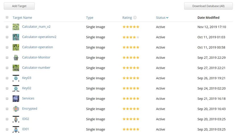
Target star rating
Image target markers are detected based on natural features that are extracted from the
target image and then compared at run time with features in the live camera image. The
star rating of a target ranges between 1 and 5 stars; although targets with low rating (1 or
2 stars) can usually detect and track well. For best results, we should aim for targets with
4 or 5 stars. To create a trackable that is accurately detected, we should use images that
are:
Attribute Example
Rich in detail Street-scene, group of people, collages
and mixtures of items, or sport scenes
Good contrast Has both bright and dark regions, is well
lit, and not dull in brightness or color
No repetitive patterns Grassy field, the front of a modern house
with identical windows, and other regular
grids and patterns
20Figure 15 Star rating of markers in Vuforia database
Features
A feature is a sharp, spiked, chiseled detail in the image, such as the ones present in
textured objects. The image analyzer represents features as small yellow crosses. Increase
the number of these details in your image and verify that the details create a non-repeating
pattern.
Figure 16 Features recognition.
Button defines
Hidden button provides a useful mechanism for making marker interactive. The size and
placement of hidden buttons must be considered when designing them. There are several
factors that will affect the responsiveness and usability of hidden buttons.
211. The length and width of the button.
2. The area of the marker that it covers.
3. The placement of the button in relation to the both the border of the image,
and other buttons on the marker.
Button events are triggered when a significant proportion of the features underlying the
area of the button are concealed from the camera. This can occur when the user covers
the button or otherwise blocks it in the camera view. For this reason, the button should be
sized appropriately for the source of the action it is intended to respond to.
Figure 17 Hidden marker’s button area.
Evaluate sensitivity
We also need to evaluate the sensitivity of buttons. Buttons with a HIGH sensitivity will
triggered more easily than those with a LOW sensitivity. The button's sensitivity reflects
the proportion of the button area that must be covered, and the coverage time. We need to
test the responsiveness of each of buttons in a real-world setting to verify that they
perform as expected.
224.2.2 Example of Application: AR Calculator
The AR calculator is consisting of two kinds of visual markers. One is AR marker for
show the result by AR. The another one is auxiliary markers for user can input the
numbers and operation.
System Output
Figure 18 Monitor marker.
The AR marker part can show the 3D virtual contents which perform like the traditional
AR system. In this case, the marker will show a 3D virtual calculator. This 3D model will
output information to the user: show the number the user input or the calculated result.
Just perform as the monitor part in traditional physical calculator. So, we also can call this
kind of marker as monitor marker.
Figure 19 Calculator 3D model.
23User Input
Figure 20 Hidden marker.
For the user input, we also design the input markers. This kind of auxiliary markers cannot
generate the 3D virtual AR contents but can help user to make some interaction with the
AR contents which is generated by AR marker in the same camera view. Because the user
needs to use their finger to hide the specific button area to input the information, we also
can call this kind of markers as hidden marker.
Combining markers
As the result, user can combine these three markers and scan them by one camera. Then
they will get a 3D virtual calculator by AR and put the finger on the button area defined
in hidden marker to input some numbers and operations to calculate. Result will be shown
by AR. The interaction between the user and AR calculator is very intuitive and
understandable. Every user who have no guidance also can realize how to use this AR
calculator in very short time.
24Figure 21 Combine three markers.
Enhance the Algorithm of hidden marker
About the hidden marker’s algorithm. We try to enhance the hidden logic. As 5.3 input
commands part shows, we just using 1-dimension buttons layout for input the information.
Because if the user’s hand hides multiple area, system will recognize the multiple button
has been pressed and have a lot of wrong inputs. But in our AR calculator’s case, 1-
dimension buttons layout for numbers input is not natural. In daily life, people always
input numbers by 3X3 2-dimensions buttons layout. So, we enhanced our number input
marker.
Figure 22 Re-design the number input marker.
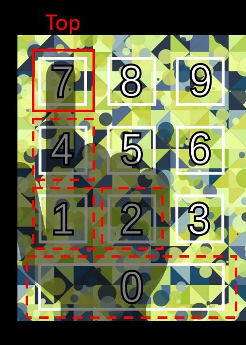
25Figure 23 Recognize the top button area user pressed marker.
As figure shows the new number input markers using this kind of 2-dimensions buttons
layout. For the user input we add some new logic for it. When the system detects the
button area has been hidden, the system will not generate the input commands at once.
System will start to wait for 1 second give the time to user’s hand slide over the marker
and fix his gesture. After the user’s gesture is fixed, the system will try to recognize the
multiple button areas hidden by user’s hand and calculate which is the top button area and
generate the top button area’s command.
Figure 24 Input number by 2-dimensions buttons layout marker.
As the result, our AR calculator can use this kind of algorithm to provide more natural
26number input layout for the user without 1-dimension buttons layout.
4.2.3 Example of Application: AR Piano
We have introduced a kind of input method by users put their fingers on the auxiliary
marker’s button area to input commands. To enhance the hidden markers algorithm for
recognition, user can use 3X3 2-dimensions buttons layout to input numbers in the AR
calculator application we have mentioned before.
In this part we use this method to make the new application named AR piano. This
application support user can have the multiple touch to input the multiple commands at
the same time.
Figure 25 AR piano marker and phonic.
Multiple Touch
As the formal piano in the real-world. If user touch one key, the piano will generate single
tune at one time, we call it monophonic. And if user touch several keys at the same time,
the piano will generate several tunes at same time and combine them as a new voice, we
call it polyphonic. In this research we make the AR piano by our AR system, and can
generate polyphonic by multiple touch.
27Figure 26 Multiple touch.
As the figure shows, user touch the C, E and A keys at the same time, the system will
generate the C+E+A piano tune voice together and make a polyphonic voice.
Because of we use the 2-dimensions buttons layout ‘s algorithm for recognition in this
application, touch the black key to play some tunes and multiple black key touch to play
polyphonic are also available.
284.3 Auxiliary Marker
4.3.1 Personalization
The identity of the user is an important condition for the customized AR display. The
system to display different 3D virtual content for users with different identities is one of
the cores of customized Augmented Reality. In our system, we use a kind of auxiliary
marker connect to the database which is store the user information. And when the user
put the auxiliary marker with the AR marker, the user information data will be checked
by system and show the customized contents to the user.
Figure 27 Two kinds of personal auxiliary marker and information.
In this research we have set an AR marker in the lab. The fictitious student A and student
B will receive different information on the 3D-virtual Call-board activated by this AR
marker. Because that when they want to get information from this AR marker, they need
to put their own auxiliary marker which contains their personal information with the AR
marker together.
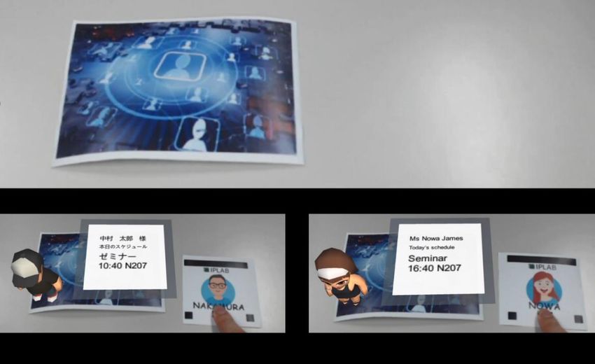
29Figure 28 Get customized information from the AR marker.
When there is no auxiliary marker, the AR marker will not show anything, like figure 28
(a) shows. And after the student put his own auxiliary marker with it, the AR content will
be shown. We can see:
Nakamura: He will see his today’s schedule by Japanese according to his class
and prefer language. He also can see his 3D virtual avatar by AR, like figure 28
(b) shows.
Nowa James: She will see her today’s schedule by English according to her class
and prefer language. She also can see her 3D virtual avatar by AR, like figure 28
(c) shows.
As the result, our system supports two difference nationality and class students in one lab
can get their different schedule from one AR marker just by putting their auxiliary marker
with the AR marker without any ID or password input.
304.3.2 Encryption/Decryption
Sometime the providers of 3D virtual content do not want all the users to see the hidden
information. In the other hand, give other people your personal account and password is
very dangerous. In our research, the user can use the auxiliary card which can perform as
a key to unlock some encrypted AR contents. The key is only for decrypting and does not
contain any personal information. We designed two simple usage scenarios to show how
encryption/decryption part is working in this system.
Usage Scenario A – AR mail
In the usage scenario of this research, there are two users: user A and user B. User A
prepare a mail which contains AR contents to user B for inviting user B and his family to
user A’s house. Because of the address information, user A does not want other people
can see the contents, so he encrypted the AR mail then post it and pass the auxiliary key
marker to user B by another way.
Figure 29 Encrypted AR mail.
31User B received mail and key by two different ways. If he just using the camera scan the
mail marker without auxiliary key marker, he only can see the text “No permission”, like
figure 5.11 (a). And if he put the auxiliary key marker with the mail marker, the 3D virtual
contents containing 3D avatars, address information, map and photo will be shown, like
figure 5.11 (b). And if he wants to let his family know this, just need to pass the mail and
auxiliary key marker. He does not need to share his account and password.
Usage Scenario B – AR announcement
In Libowen’s research, the 3D virtual Call-Board at Sakura House shows the permission
check function of the system. In the pre-set, user A is not a resident of Sakura House, so
he has no permission to make the hidden 3D-virtual Call-Board display. Instead, the
system will give her a "No Permission!" message. In the other hand, the fictitious user B
is the resident of the Sakura House in the pre-set. So, he can see the notification from the
system about the dealing with old furniture.
The usage scenario of our research, the principal of Koharu house always need to tell
some announcement from door to door in the past. Looks like the disaster prevention and
early warning. We try to use our system and set permission for Koharu’s residents. And
the user who is not the resident of Koharu house cannot acquire the information on the
AR announcement marker. The principal just needs to share the key marker to the
residents, anytime, anywhere and let them gain the access to the content which he has set
up before.
32Chapter5
System Implementation
5.1 Develop Environment
We established the system and built the 3D module on Unity and use the C sharp as the
development language. We use Vuforia-Unity SDK (As of 2017.2, Unity integrates the
Vuforia Engine), AR Toolkit SDK to detect the AR-marker and QR code scanner to detect
the QR code in camera view. Finally, we integrated them in one system and add 3D virtual
content in the user’s view.
Figure 30 Unity3D, Vuforia, AR Toolkit.
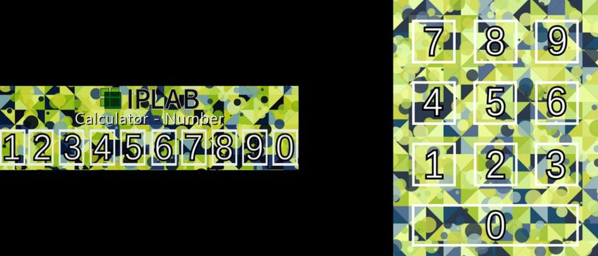
335.2 System Hardware
We have used the WEB camera (Velbon EX-Mini S & HD Pro Webcam C920) for detect
the markers. A PC with the windows 10 operation system provides a platform for the
system to process the program. Our system also can be installed in other platform looks
like smartphone and AR glasses.
Figure 31 PC.
Figure 32 Web camera.
345.3 Project Scene
Once the project is created, Unity structures it into scenes. Every scene is like a game
level and is loaded when required. Each unique Scene file is a unique level. In each Scene,
we can place our environments, obstacles, and decorations, essentially designing and
building our application in pieces.
Application menu is considered a scene too and its function is to manage the application
different scenes. Scenes that use device’s camera as AR camera launch the capture process,
define the tracker and execute its renderization. AR Cameras are the eyes of the
application. Everything the player will see is through AR camera. Users can position,
rotate, and parent camera just like any other Game Object.
Figure 33 Different scenes.
Figure 34 Elements in the scene.
355.4 3D Virtual Content Modeling
Our system will display these 3D virtual contents to the users. So, we need to create those
fictitious 3D virtual content in advance. We use 3Dmax and Unity 3D to accomplish this
part of work.
5.4.1 Modeling in 3DMAX
We build the AR Calculator’s 3D virtual model in 3DMAX. We need to define the
calculator’s outline at first. For the realistic, we consult the traditional Calculator’s shape
and size in the real-world. And after that, we add the button and screen on the model. The
button layout is also like the traditional calculator’s design and combine with the digital
calculator button area and color.
Figure 35 Building the outline.
Figure 36 Adding buttons.
365.4.2 Modeling in Unity3D
In the personalization and Encryption/Decryption parts, we have created several 3D
virtual panel in the scene. The system will display these kinds of 2D panel to the user
when they put their auxiliary markers with the AR marker together.
We designed the 3D virtual panel like the call board in the real-world. And not only the
text information, we also can add some pictures in the layout. The size of panel needs to
be reset for fitting our markers.
Figure 37 The panel of UI.
37After we created the panel, we also need to add the text script on it. The size is fit to the
mother panel and we can design the font size, color and other attributions by text script.
Figure 38 Rect transform.
Figure 39 Text edit panel.
38As figure shows, in the Encryption/Decryption part. If the user used the correct key
auxiliary card with the AR mail, he can see the address information and two pictures about
the street for the user can easily find the building where is the inviter lives in.
Figure 40 No Permission UI.
Figure 41 The AR invitation card in detail.
39As figure shows, in the personalization part. If the user used his/her id auxiliary card with
the AR marker, he can see his/her schedule and 3D avatar.
Figure 42 The AR personalization card for Nakamura.
Figure 43 The AR personalization card for Nowa.
405.5 Multiple recognition
5.5.1 Vuforia
Based on Vuforia service, our system can recognize the image target marker with natural
feature points. For using this engine, we need to get the free license from their homepage
(https://developer.vuforia.com/legal/license).
After we get the license, we can upload our marker to the database and get the analysis
data. For best results, we should aim for uploaded image target markers with 4 or 5 stars.
And If the target is not focused well in the camera view, the camera image result can be
blurry, and the target details can be hard to detect. Consequently, detection and tracking
performance can be negatively affected. We need to make use of the appropriate Camera
Focus Mode to ensure the best camera focus conditions.
Figure 44 Getting the license key from Vuforia.
41Figure 45 The image target markers database.
Figure 46 Image target marker ‘s information in detail.
We can download the Vuforia database from target manager page and import it into our
unity project. Then we can track the image target marker and generate AR virtual contents
above it in our system.
42Figure 47 Import the database.
After downloaded the database and import it, we need to active the Vuforia Augmented
Reality in unity’s player setting panel.
Figure 48 Active the Vuforia.
43Then open the inspector of Vuforia add our license key and set the number of max
simultaneous targets. We also need to check the box of “Load Marker Database” and
“Active” to make the system works.
Figure 49 Input the license key.
44Because we use web camera HD Pro Webcam C920 in our research, the camera device in
Vuforia setting need to be changed from integrated camera.
Figure 50 Change the camera.
After all the preparations have been down, we need to build an AR camera in the scene
and create an image target by Vuforia engine.
Figure 51 Add image target marker.
45The AR content we want to show above the image target marker need to be registered
below the image target.
Figure 52 Register the AR content above the marker.
Then we can use our web camera to scan the image target marker and see the AR content
above it.
5.5.2 AR toolkit
The AR toolKit Library is available for download for the Windows, Linux, SGI and
MacOS X operating systems. In addition to any base requirements for Unity, the AR
toolKit for Unity plugin have the following requirements:
1. ARToolKit for Unity 5.3.2 requires Unity Pro v4.5.5f1 or later.
2. If targeting Android, Android v4.0.3 and later is supported.
3. If targeting iOS, Xcode tools v5.0.1 or later is required. iOS v7.0 and later is
supported.
4. If targeting OS X, Xcode tools v5.0.1 or later is required. OS X v10.7 and
later is supported.
5. If targeting Windows Phone 8.1 or Windows Store 8.1, Visual Studio 2013
SP2 running on Windows 8.1 or later is required.
After imported the SDK in unity3D, we can track the AR toolkit marker in our system.
46The marker building need to use the genTexData.exe file in the bin document we
downloaded.
Figure 53 Generating the AR toolkit marker by genTexData.exe.
The marker file name generated by genTexData.exe will be end with: fset, fset3 or iset.
Then we can track them in our system.
Figure 54 Setting the marker.
Then we can register the AR contents or some trigger event with the marker in unity.
Figure 55 Register the AR content.
475.5.3 QR code
Before we write the QR code scanner script in our unity project, we need to install the
zxing.unity.dll from the http://zxingnet.codeplex.com/ in our unity plugin folder. ZXing
("zebra crossing") is an open-source, multi-format 1D/2D barcode image processing
library implemented in Java, with ports to other languages. Then we can build a QR code
scanner script in our system.
Figure 56 QR code reader script.
We also can render the QR code from text in unity to generate new markers in unity.
Figure 57 QR code render script.
48As the example, we generate a QR code which can express IPLAB’s homepage URL.
The QR scanner can get the correct information from it and access to the webpage.
Figure 58 Scan the QR code and access to IPLAB home page.
5.5.4 Marker measuring
For the system can process multiple markers in a certain order, we need to measure the
markers position at first. In the unity we need to set the world center mode as camera.
Figure 59 Change the world center mode to camera.
The World Center Mode allows specifying how the World reference frame is set during
target / trackable tracking.
- FIRST_TARGET: The World is fixed with respect to the first detected
- SPECIFIC_TARGET: same as FIRST_TARGET, except here you explicitly
specify (in the Editor) which target is the "anchor".
- CAMERA: in this case the AR Camera is fixed (fixed position and orientation)
in the scene, while the Target objects move around it.
49Then we try to get the pose matrix which returns the 3D position of the target in the center,
assuming the camera is at (0,0,0), and then convert this into 2D camera space, and then
transfer this into screen space.
Figure 60 Take the camera space point and transform it into screen space.
505.6 Hidden marker design
For designing the hidden marker, we need to define the button area at first. Because we
achieve this function by Vuforia virtual button service, the image target marker’s natural
feature points can help us to distinguish the different area we predefined if the image is
recognizable enough.
Figure 61 Feature points and button area.
We set the events are triggered when a significant proportion of the features underlying
the button area we defined are concealed from the camera. This can occur when the user
covers the button by their finger in the camera view. It also supports user can have
multiple touch with the hidden marker and trigger the multiple events at the same time.
After we designed and upload them to the Vuforia database as markers. We can import
them into unity and start to define the button area. In our case, we are using green color
to define the button area.
Figure 62 Define the area.
51You can also read