RMIS USER MANUAL MANUALE UTENTE - Elettrotest
←
→
Page content transcription
If your browser does not render page correctly, please read the page content below
RMIS

    USER MANUAL
    MANUALE UTENTE

1        RMIS 30A / 2 USER MANUAL – Rev 06 – 16/03/2021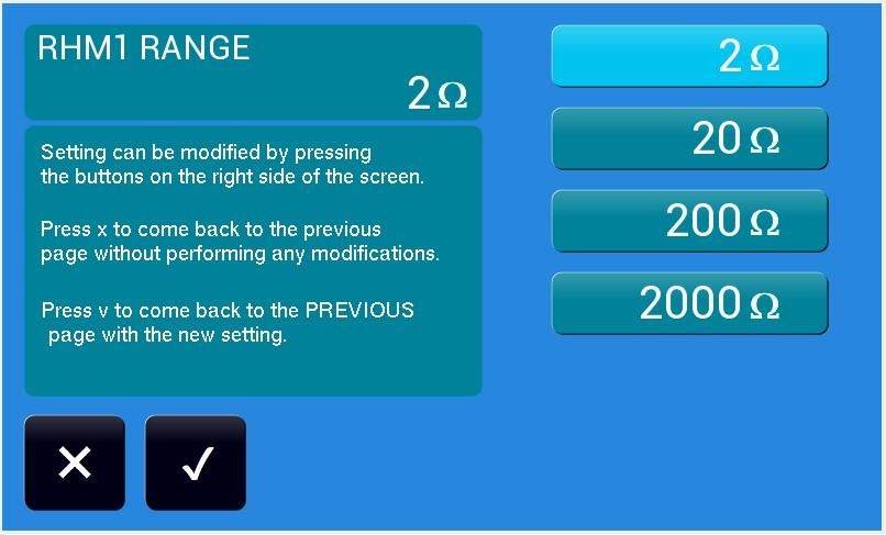
SAFETY WARNINGS

The manufacturer urges users to read the user manual for our products before installation.
The installation must be carried out by qualified technical staff. The non-observance of the
warnings in this manual can cause electric shocks, even fatal ones.

Please find below some general safety warnings.

    • This equipment must be connected to the mains supply using the appropriate safety
      devices.
    • RMIS must be connected to safety ground through the correct connections. The non-
      observance or the degradation of this earth connection can lead to electric shocks, even
      fatal ones.
    • Disconnect RMIS from the mains before any work on the equipment and on the connected
      power loads.
    • Load connection (U/V/W) or measurement connection (INJECTION/SENSE) must be done
      with instrument disconnect to power supply or in stand by or with BYPASS ON, in order
      to have no injection current. Anyway an high voltage spikes (1,5 KV) can be in INJECTION
      connection
    • Before touching the load or the connection cables make sure that the power supply on the
      device has been disconnected.
    • Avoid heavy shocks to the equipment (especially during transport) or exposure to extreme
      weather conditions.
    • Any damage to the product due to transportation, incorrect installation or improper use is
      not covered by the guarantee supplied by the manufacturer.
    • Do not use the equipment in explosive environments or in the presence of dust, acids or
      corrosive and/or inflammable gases.
    • Tampering with or dismantling any component in the equipment will void the warranty
      automatically.
    • Do not operate or store under conditions where condensing may occur or where
      conductive debris may enter in the case.
    • Keep the ventilation holes on the front and rear free from obstruction

             The manufacturer declines all responsibility for damage to people or things caused
             by an improper use of its products.

             ELECTRIC RISK
             There are dangerous voltages inside RMIS and over the output connector.
             The non-observance of the warnings suggest in this manual can lead to electric
             shocks, even fatal ones.

2                          RMIS 30A / 2 USER MANUAL – Rev 06 – 16/03/2021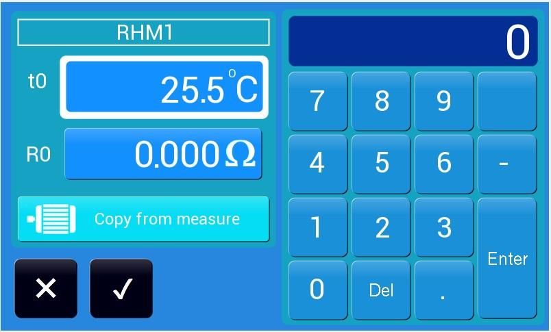
DISPOSAL

        INFORMATION FOR USERS ON THE CORRECT HANDLING OF WASTE
              ELECTRICAL AND ELECTRONIC EQUIPMENT (WEEE)

In reference to European Union directive 2012/19/EU issued on 24 July 2012 and the related
national legislation, please note that:

    • WEEE cannot be disposed of as municipal waste and such waste must be collected and
      disposed of separately;
    • the public or private waste collection systems defined by local legislation must be used. In
      addition, the equipment can be returned to the manufacturer at the end of its working life
      when buying new equipment;
    • the equipment may contain hazardous substances: the improper use or incorrect disposal
      of such may have negative effects on human health and on the environment;
    • the symbol (crossed-out wheeled bin) shown on the product or on the packaging and on
      the instruction sheet indicates that the equipment must be disposed of separately;
    • in the event of illegal disposal of electrical and electronic waste, the penalties are specified
      by local waste disposal legislation.

3                           RMIS 30A / 2 USER MANUAL – Rev 06 – 16/03/2021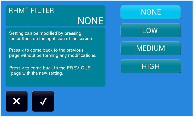
INDEX
1.  INTRODUCTION ............................................................................................................................ 5
  1.1. MAIN FEATURES .................................................................................................................... 5
    1.1.1.1. General information ................................................................................................... 5
    1.1.1.2. General specifications ................................................................................................ 8
  1.2. MODELS ................................................................................................................................. 9
2. MECHANICAL DRAWINGS ............................................................................................................ 9
    2.1.1.1. 99150200 RMIS 30A/2................................................................................................ 9
3. NOTES FOR USERS ...................................................................................................................... 10
  3.1. EXTERNAL VIEW................................................................................................................... 10
    3.1.1.1. Front Panel ............................................................................................................... 10
    3.1.1.2. Rear Panel................................................................................................................. 11
4. INSTALLATION ............................................................................................................................ 12
  4.1. GENERAL NOTES .................................................................................................................. 12
    4.1.1.1. INSPECTION .............................................................................................................. 12
    4.1.1.2. USER PREPARATION ................................................................................................. 12
    4.1.1.3. PROTECT ................................................................................................................... 12
  4.2. WIRING DIAGRAM ............................................................................................................... 13
    4.2.1.1. Measurement at 2 wires .......................................................................................... 13
    4.2.1.2. Measurement at 4 wires .......................................................................................... 14
5. REMOTE CONTROL AND EXTERNAL CONNECTION .................................................................... 15
  5.1. SERIAL REMOTE CONTROL .................................................................................................. 15
    5.1.1.1. RS232 Serial cable .................................................................................................... 15
    5.1.1.2. PINOUT RS485 .......................................................................................................... 15
  5.2. EXTERNAL AUXILIARY CONNECTION ................................................................................... 15
6. ACCESSORY ................................................................................................................................. 16
    6.1.1.1. 99150200 RMIS ........................................................................................................ 16
7. LOCAL OPERATION ..................................................................................................................... 17
  7.1. START UP PROCEDURE ........................................................................................................ 17
    7.1.1.1. POWER ON ............................................................................................................... 17
    7.1.1.2. MAIN SCREEN ........................................................................................................... 17
    7.1.1.3.   RESISTANCE PAGE................................................................................................... 18
    7.1.1.4. RESISTANCE RANGE SELECTION ............................................................................... 19
    7.1.1.5. FILTER LEVEL SELECTION .......................................................................................... 20
    7.1.1.6. BYPASS COMAND ..................................................................................................... 20
    7.1.1.7. INITIAL LOAD SETTINGS PAGE .................................................................................. 21
    7.1.1.8. START TEST ............................................................................................................... 21
  7.2. TEMPERATURE MEASUREMENT ......................................................................................... 22
    7.2.1.1. TEMPERATURE PAGE ................................................................................................ 22
  7.3. GENERAL SETTINGS ............................................................................................................. 22
    7.3.1.1. SETTINGS MENU ....................................................................................................... 23
    7.3.1.2. USER SETTINGS ......................................................................................................... 23
    7.3.1.3. OPERATOIN SETTING ................................................................................................ 24
8. APPLICATION WARNING ............................................................................................................ 25
9. REMOTE CONTROL ..................................................................................................................... 26
  9.1. PORT .................................................................................................................................... 26
  9.2. PROTOCOL ........................................................................................................................... 26

4                                        RMIS 30A / 2 USER MANUAL – Rev 06 – 16/03/2021
9.2.1.1. MODBUS RTU Protocol............................................................................................. 26
    9.2.1.2. Active command ....................................................................................................... 26
    9.2.1.1. HOLDING REGISTER .................................................................................................. 27
    9.2.1.1. INPUT REGISTERS ..................................................................................................... 29
 10. GUARANTEE ............................................................................................................................ 30

 1. INTRODUCTION
 RMIS is essentially based on the typical principle of resistance meters, that is, on the injection of
 current on the load to be measured. The resistance measurement is carried out through the
 ratiometric ratio between the voltage on the load, purified by the alternate power supply
 component, and the direct component of the current injected on the load.
 To prevent the injected current from entering the network, electrolytic capacitors of high capacity
 and quality are present in the instrument. The high capacity of the capacitors allows to minimize
 the voltage drop on them with high current absorption, in this way the voltage on the load does
 not appreciably differ from that of the network.

                                                                                               RMIS
                                                                                               BYPASS

                  Differential /
                   Magneto-                            Inverter                             Decoupling                               EUT
LINE                                                                                        Capacitors
                    thermal                           (optional)                                                                     Load
                  protections

                                                                                         Measurement
                                                                                           system

                                                              Figure 1.1

     1.1. MAIN FEATURES

                       1.1.1.1.           General information

 The measurement of the temperatures of the windings of a motor or other electrical machines
 (transformers, contactor coils, etc.) is increasingly necessary during the design phase for a correct
 sizing of the same in relation to the operating conditions and presents a series of difficulties
 dependent on the measurement method implemented.

 5                                      RMIS 30A / 2 USER MANUAL – Rev 06 – 16/03/2021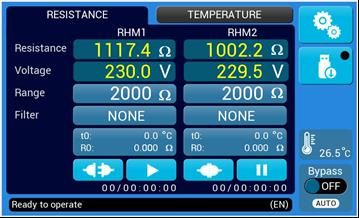
To measure the heating of the windings of a motor, the methods mainly used are that with
thermocouple (direct method) and that of resistance with milliohmeter in continuous (indirect
method).
The thermocouple method has the advantage of being able to continuously monitor the
temperature of the motor windings and allows you to check the intervention point of any thermal
protector inserted on the motor.
However, there are several drawbacks; the main one is the need to insert the thermocouple in
direct contact with the windings; this involves a specific construction of the motor, moreover the
measurement of the temperature strongly depends on the point where the thermocouple is
inserted.
The second method consists in checking the changes in resistance of the material under test
(copper, aluminum, etc.) due to the effect of heating and, knowing its relative thermal coefficient,
go back to the temperature.
The formula normally used, also in relation to specific regulations, is the following for
temperatures in degrees centigrade:
R2 – R1
t = ——— ( + t1) - ( t2 - t1 )
R1
where: t = over rising temperature
R1 = test beginning resistance
R2 = test end resistance
t1 = test beginning ambient temperature
t2 = test end ambient temperature
= temp. Coefficient (cu = 234.5)
WARNING
R1 must be measured when winding is stable at t1 .
The measurement is performed with a milliohmeter or with a bridge at regular intervals by
disconnecting the load under test from the power supply in order to read the resistance of the
windings. This gives a precise temperature measurement because it affects the entire winding
involved.
With this method, very cumbersome, it is not possible to continuously monitor the resistance of
the windings on a motor in operating conditions and the fact of having to disconnect the power
supply leads to an alteration of the measurement of the temperature variation as a function of
time: this drawback it is due to the cooling of the motor during the acquisition of the resistance
measurement and does not allow to verify the intervention point of a possible thermal protector
due to the impossibility of carrying out resistance measurements after the intervention of the
protector itself.
RMIS is an instrument that gives the possibility to read the resistance both with a two-wire and a
four-wire measurement (compensated measurement) of a load in operation, greatly simplifying
and making the measurement more precise.
RMIS gives ATcalculation, starting by setting condition (R0,t0) that user can have from other test
or can read from the eut load. This vale will be use for R1,t1 . Reading must me done in stable
temperature condition
A working condition (switching on BYPASS) is foreseen in which the load is directly fed and the
instrument measures the input voltage between the two phases..
6 RMIS 30A / 2 USER MANUAL – Rev 06 – 16/03/2021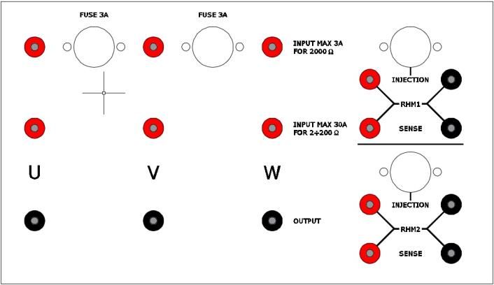
The choice of this position is requested when, for example during the motor starting, high current
peaks may occur, higher than the limits allowed by the instrument.
Acting on switching OHM RANGE it is possible to choose among four values of range: 2, 20, 200,
2000 ohm.
With FILTER mode (low-medium-high) it is possible to choose the time of response of the
instrument, adapting it to the various demands, decreasing the disturbances to the measure
caused from the pulsating loads like for example the motors for compressor.
RMIS allows the measurement at four wires of the load resistance, which allows to take the
measurement on loads far from the instrument and avoiding that itself results faulty. This type of
measure necessitates only three ulterior connections (SENSE contact-plugs) of small section.
RMIS communicates with any computer through an RS232 or RS485 serial port and a LAN port; it
also has the possibility of being addressable, this allows up to ten RMIS to be connected in parallel
on the same serial port at no additional cost to any expansion cards. The setting of the instrument
address is possible throught the computer; also note that the serial output is optically isolated
from the instrument itself, thus ensuring high operating safety.
Instrument is considered “FLOATING” because there are 2 single capacitive filters, in order to
separate up to 2 coils, to measure separately each coil.

7                           RMIS 30A / 2 USER MANUAL – Rev 06 – 16/03/2021
1.1.1.2. General specifications
PARAMETER VALUE
Input Voltage Supply 230Vac ± 10%
Input Frequency 50/60Hz
Fuses Supply = 5x20 2,5A Fast
Input Line 3A = 10X38 AM-4A
Resistance range 2Ω, 20Ω, 200Ω, 2000Ω
Voltage range 500Veff rms 40400 Hz – linear reducing
12.5V/Hz until 10Hz (PWM 4-20 Khz)
Accurancy 0.5% f.s.
12 bit resolution (0.025%)
Filtering reading resistance None : Light Hw LP filter
only to remove high frequency variation
Low : Hw LP filter – 0.2 Hz
Medium : Sw filter - remove big variation
High : HW LP + SW
Typical injected DC current 100mA - 2Ω f.s.
100mA - 20Ω f.s.
10mA - 200Ω f.s.
1mA - 2000Ω f.s.
Disconnect with bypass on
Current 3 A (1,5A*) 20400 Hz
30 A (15A* ) 20400 Hz
* reduced linearly until 10 Hz
Decoupling capacitor with bypass 6,800 uF @3A line
60,000 uF @30A line
Short circuit with bypass on
Voltage protection 3 A line – limiter and fuse
30 A – voltage detect with BYPASS
Temperature measurement 0 ÷ 50°C
Linearity 0.05°C (with linearized probe)
Accuracy 0.5°C (constant error due to the
probe and possibly correctable)
User interface 7” Touch Screen Display
Communication Interface RS232, RS485, ETHERNET
Insulation 2000Vdc 60 sec.
Transmission protocol Start 1 bit, 8 bit data, No parity, Stop bit 1
Fw version 10060
8 RMIS 30A / 2 USER MANUAL – Rev 06 – 16/03/2021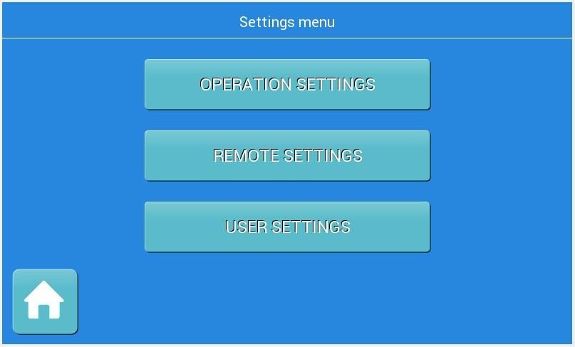
1.2. MODELS

    Model   Code     Measure Limits     Resistance Range          Dimension   Weight

                     500Veff (RMS)       2, 20, 200, 2000       RACK 4U-19”
30A/2/R 99150200                                                               22Kg
                     30Aeff (RMS)              Ohm            483x430x178mm

2. MECHANICAL DRAWINGS
              2.1.1.1.    99150200 RMIS 30A/2

9                        RMIS 30A / 2 USER MANUAL – Rev 06 – 16/03/2021
3. NOTES FOR USERS
 3.1. EXTERNAL VIEW

               3.1.1.1.       Front Panel

                              1                                                        2      3     4

                                             Figure 2.1

     Item       Name                                         Description

                                  Input programming data or options by manipulating touch screen
      1      Touch Screen
                                                           desired one
                                      This interface is used for connect data storage to save log
              USB Type A
      2                                                       information
               Interface
              USB Type B
      3                            This interface is used for upgrade firmware (only for expert use)
               Interface
                                        Press this button to switch on/off the instrument panel.
                                  In order to have bypass active during standby , some internal parts
      4     Stand by Switch
                                           are supplied with plug inserted and with voltage.

10                          RMIS 30A / 2 USER MANUAL – Rev 06 – 16/03/2021
3.1.1.2. Rear Panel
1 23 4 5 6 7 8 9 10 11 12 13 14 15 16 17
2 15
15
ETHERNET RS232 RS485
INJECTION AUX SIGNAL NO/NC TEMP
RHM1
SENSE
FUSE 2,5A
1
LINE 220VAC
INJECTION
RHM2
SENSE
Figure 2.2
Item Name Description
1 Output Sockets This sockets are used to output AC power to the load
2 Input Sockets (30A) This sockets are used to input max 30A power for the load
3 Input Sockets (3A) This sockets are used to input max 3A power for the load
4 Input Fuses (3A) This fuses protect the input max 3A power for the load
5 RHM2 Sense Sockets This sockets are used to connect Sense Wires to the load
6 RHM2 Injection Sockets This sockets are used to connect Injection Wires to the load
7 RHM1 Sense Sockets This sockets are used to connect Sense Wires to the load
8 RHM1 Injection Sockets This sockets are used to connect Injection Wires to the load
9 Injection Fuses This fuses protect the Injection Line from overcurrent
10 Ethernet Interface This interface is used for remote control via Ethernet cable
This terminal is used for ausiliary signal
11.1 – 11.2 Contact for start EUT.RHM1
11 Output auxiliary signals
11.3.-11.4 Contact for start EUT.RHM2
12 RS232 Interface This interface is used for remote control via the RS232 cable
13 NO/NC Interface Indicates BYPASS State (NO/NC for BYPASS off)
14 RS485 Interface This interface is used for remote control via the RS485 cable
15 Temp Connector This connector is used for reading the temperature via NTC probe
16 Input Fuses (2,5AF) This fuse protects the power line of instrument
17 Input Plug This plug is used to connect the instrument with the power line input
11 RMIS 30A / 2 USER MANUAL – Rev 06 – 16/03/20214. INSTALLATION
4.1. GENERAL NOTES
4.1.1.1. INSPECTION
After unpacking the product, please inspect any damage that may have occurred during the
shipment. Save all packing materials in case the product has to be returned one day. If any
damage is found, please file a claim with the carrier immediately. Do not return the product to the
factory without obtaining the prior Return Merchandise Authorization (RMA) acceptance from
ELETTROTEST SPA.
4.1.1.2. USER PREPARATION
After placing the instrument in the dedicated rack compartment, on the rear pannel connect a
supply cable 2P+T of adequate size (3x1,5mm2 recommended) using the socket provided with the
instrument.
4.1.1.3. PROTECT
LINE/INVERTER
FUSES CONTACTOR
RMIS LOAD
Figure 3.1
WARNING:
Before turning on the product, all protective grounding terminals, extension cords, and devices
connected to the product must be connected to a protective ground. Any interruption of the
protective ground will cause a potential shock hazard that could result in personal injury.
12 RMIS 30A / 2 USER MANUAL – Rev 06 – 16/03/20214.2. WIRING DIAGRAM
4.2.1.1. Measurement at 2 wires
In case a high accuracy of the measure is not requested, the contact-plugs of SENSE may be
bypassed with the correspondent contact-plugs of OUTPUT.
This configuration is advisable only with loads of high internal resistance (2000 ohm of span),
becoming in this case inconsiderable the resistance of the wirings.
INPUT 1 PHASE
NOTICE:
it’s possible to measure UV resistance
using RHM1 channel; in additional it’s
possible use RHM2 channel for measure
UW resistance, must be keep the common
on the common phase of the motor (U in
this configuration)
Single Phase
Load
Figure 4.1
INPUT 3 PHASE
NOTICE:
in this case the reading is influenced by
two windings of the load.
For simmetrical load: resistance of phase =
½ read resistance
in this case the reading is influenced
from all three windings of the load.
For simmetrical load: resistance of phase =
3/2 read resistance
Only RHM1 is usable (or RHM2) . The other
channel is usable only with three-phase load
with neutral wire (fig. 4.4).
Three Phase
Load
Figure 4.2
13 RMIS 30A / 2 USER MANUAL – Rev 06 – 16/03/20214.2.1.2. Measurement at 4 wires
In this configuration the measurement is not influenced by the wirings resistance to the load.
INPUT 1 PHASE
Single Phase
Load
Figure 4.3
INPUT 3 PHASE
Three Phase
Load
Figure 4.4
14 RMIS 30A / 2 USER MANUAL – Rev 06 – 16/03/20215. REMOTE CONTROL AND EXTERNAL CONNECTION
RMIS can be remotely controlled via RS232, RS485 or ETHERNET communication port. Please refer
to the protocol manual for details.
5.1. SERIAL REMOTE CONTROL
5.1.1.1. RS232 Serial cable
Use a serial cable according to the standard defined in the figure below.
WIRING CONNESSION
PC RMIS
DB9 Poles Female DB9 Poles Male
2 2
3 3
5 5
5.1.1.2. PINOUT RS485
DB9 Poles Male
1: B
2: A
5: GND
5.2. EXTERNAL AUXILIARY CONNECTION
AUX SIGNAL
1 2 3 4 5 6 7 8
BYPASS (*)
1-2 START RHM1 contact (Start=closed) 1-4 BYPASS OFF = Open 1-5
24 V– 0,5 A max BYPASS ON = Closed Ambient
3-4 START RHM1 contact (Start=closed) 3-5 BYPASS OFF = Closed temperature
24 V– 0,5 A max BYPASS ON = Open NTC Probe
5/6/7/8 N.c. 2 n.c. 10Kohm @25°C
(*) Connected to BYPASS relay
15 RMIS 30A / 2 USER MANUAL – Rev 06 – 16/03/20216. ACCESSORY
6.1.1.1. 99150200 RMIS
Description Pcs
1 FUSE 5X20 CF - 2.5A FAST 1
2 FUSE 10X38 CARTRIDGE 300MA 600VAC/VDC 1
3 FUSE 10X38 AM-4A 1
4 USB KEY-KIT 1
16 RMIS 30A / 2 USER MANUAL – Rev 06 – 16/03/20217. LOCAL OPERATION
The product can support local operation or remote operation enabled via complete
communication interfaces, such as RS232, RS485, Ethernet. In this section, the local operation
enabled via the 7-inch touch screen on the front panel will be described.
The product is configured for local operation when it is turned on.
7.1. START UP PROCEDURE
7.1.1.1. POWER ON
Apply power and press the power switch (see point 2.1.1) to turn on the product then the touch
screen located on the front panel will light up and will be displayed the boot page with logo and
the revision of firmware installed
NOTICE:
as soon as RMIS is
switched on, it performs
several test cycles.
In the event of a
malfunction, the test
stops and the machine
indicates the
"communication not
detected" alarm on the
display.
7.1.1.2. MAIN SCREEN
When the user turns on the product, the touchscreen shows the MAIN page after the startup
procedure. The MAIN screen shows the page dedicated to measuring resistance and the page
relating to the graph of the temperature trend of the load winding.
The RMIS starts at the factory default configuration (for the first start) or at the last stored setting.
Figure 7.2
RESISTANCE MEASUREMENT
17 RMIS 30A / 2 USER MANUAL – Rev 06 – 16/03/20217.1.1.3. RESISTANCE PAGE
1 2 3 4 5 6 7 8 9 10 11 12 13 14 15 16 17
Figure 7.3
Item Name Description
1 Information bar Displays information for the user
Start and Stop the test for the RHM1 channel resistance
2 RHM1 START button
measurement
3 RHM1 TEST button Enable or disable the auxiliary output of RHM1
Allows initial settings of the resistance and temperature for
4 Initial load settings
the RHM1 channel load resistance measurement
Allows selection of the filtering level for the RHM1 channel
5 Filter button
resistance measurement
6 Range button Allows selection of the resistance range for the RHM1 channel
Allows the display of the voltage on the load for the RHM1
7 Volt display
channel
Allows the display of the load resistance for the RHM1
8 Resistance display
channel
Allows the display of the load resistance for the RHM2
9 Resistance display
channel
Allows the display of the voltage on the load for the RHM2
10 Volt display
channel
11 Range button Allows selection of the resistance range for the RHM1 channel
Allows selection of the filtering level for the RHM2 channel
12 Filter button
resistance measurement
Allows initial settings of the resistance and temperature for
13 Initial load settings
the RHM2 channel load resistance measurement
Allows the display of the temperature measured by the
14 Temperature display
instrument probe
15 RHM2 TEST button Enable or disable the auxiliary output of RHM2
Start and Stop the test for the RHM2 channel resistance
16 RHM2 START button
measurement
17 Bypass button Activates and deactivates the bypass function
18 RMIS 30A / 2 USER MANUAL – Rev 06 – 16/03/2021NOTICE:
if start the test for RHM1 channel or RHM2 channel without first having set the initial resistance
and temperature values (see point 7.2.5), a CALCULATION ERROR message will appear
Figure 7.4
7.1.1.4. RESISTANCE RANGE SELECTION
By clicking on the button , allows to access the Range settings page
1 2 3 4 5 6
NOTICE:
this description
is the same for
RHM2 channel
Figure 7.5
Item Name Description
1 2 Ω button Allows select 2 ohm range
2 20 Ω button Allows select 20 ohm range
3 200 Ω button Allows select 200 ohm range
4 2000 Ω button Allows select 2000 ohm range
Allows to come back to the previous page with the new range
5 Confirm button
setting
Allows to come back to the previous page without any range
6 Cancel button
modification
19 RMIS 30A / 2 USER MANUAL – Rev 06 – 16/03/20217.1.1.5. FILTER LEVEL SELECTION
By clicking on the button , allows to access the Filter settings page
1 2 3 4 5/6
NOTICE:
this description
is the same for
RHM2 channel
Figure 7.6
Item Name Description
1 NONE button No filtering (only to remove PWM)
2 LOW button Allows select LOW FILTER level (HW filtering)
4 MEDIUM button Allows select MEDIUM FILTER level (SW filtering)
5 HIGH button Allows select HIGH FILTER level (HW+SW Filtering)
5 “✓” button Allows to come back to the previous page with the new filter setting
6 “X” button Allows to come back to the previous page without any filter modification
7.1.1.6. BYPASS COMAND
By clicking on the button , allows to active the BYPASS function; in this case the load is
powered directly and the instrument measures the supply voltage between two phases.
The choise of this position is request when, for example during the motor starting, high current
peaks may occur, higher than the limits allowed by the instrument
Figure 7.7
20 RMIS 30A / 2 USER MANUAL – Rev 06 – 16/03/20217.1.1.7. INITIAL LOAD SETTINGS PAGE
By clicking on the button , allows to access the Initial Settings page for
temperature and resistance
1 2 3 4 5 6
NOTICE:
this description
is the same for
RHM2 channel
Figure 7.8
Figure 7.7
Item Name Description
Allows to come back to the previous page with the new initial
1 Confirm button Figure 7.7
load settings
Allows to come back to the previous page without any
2 Cancel button
settings modification
Copy from measure
3 Allows to automatically store the initial load settings
button
Allows to manually enter the initial value of the load
4 R0 button
resistance (using the numeric keyboard on the right)
Allows to manually enter the initial value of the temperature
5 t0 button
(using the numeric keyboard on the right)
Allows to manually enter the initial values of resistance and
6 Numeric keyboard
temperature
7.1.1.8. START TEST
By clicking on the button of RHM1 or RHM2 channel , the measurement test for the
select channel starts and the timer will start to monitor the duration of the test
Figure 7.9
NOTICE:
before starting the test, make sure to have set the initial resistance and temperature values (see
point 7.2.5)
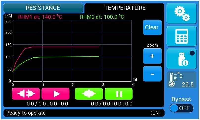
21 RMIS 30A / 2 USER MANUAL – Rev 06 – 16/03/20217.2. TEMPERATURE MEASUREMENT
7.2.1.1. TEMPERATURE PAGE
1 2 3 4 5
Figure 7.10
Item Name Description
1 RHM2 temperature Display the trend of temperature variation of RHM2 channel
2 RHM1 temperature Display the trend of temperature variation of RHM1 channel
3 Clear button Clear the temperatures diagrams
4 + button Zoom in (only for “Y” axis)*
5 - button Zoom out (only for “Y” axis)*
*NOTICE:
The “X” axis variation is calculated internally by the instrument
7.3. GENERAL SETTINGS
By clicking on the button , allows to access the General Settings page
Figure 7.11
22 RMIS 30A / 2 USER MANUAL – Rev 06 – 16/03/20217.3.1.1. SETTINGS MENU
1 2 3 4
Figure 7.12
Item Name Description
1 Home button Allows to come back to the main page
2 User Setting button Allows to access the User Settings page
3 Remote Setting button Allows to access the Remote Settings page
4 Operation Setting button Allows to access the Operation Settings page
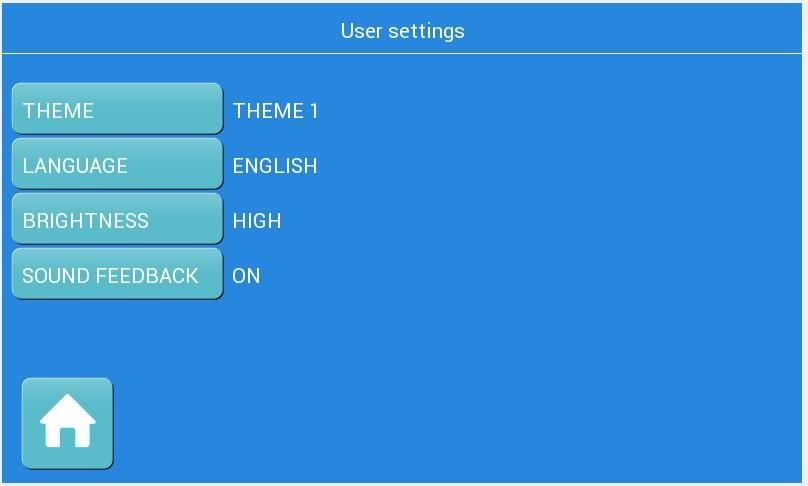
7.3.1.2. USER SETTINGS
By clicking on the general settings button , allows to access the settings menu
page
1 2 3 4 5
Figure 7.13
23 RMIS 30A / 2 USER MANUAL – Rev 06 – 16/03/2021Item Name Description
1 Home button Allows to come back to the main page
2 Sound Feedback button Allows to enable o disable audible feedback
3 Brightness button Allows to change the touch screen brightness
4 Language button Allows to change the menu language
5 Theme button Allows to change the interface colors
7.3.1.3. OPERATION SETTINGS
By clicking on the general settings button
, allows to access the settings menu page
1 2 3 4
Item Name Description
1 Home button Allows to come back to the main page
2 Bypass Mode Select MANUAL/AUTO BYPASS
3 Temperature Select temperature T0 (MANUAL/PROBE)
4 Materia Select Material Type as normative request
24 RMIS 30A / 2 USER MANUAL – Rev 06 – 16/03/20218. APPLICATION WARNING
- Decoupling capacitor can be a problem during start up of a load/motor inverter supplied
(tipical with brushless sensorless), so it’s very important to start always with BYPASS ON.
- When RMIS is plug connected with supply line and stabdby is off (Panel off) BYPASS normal
condition is ON, in order to have possibilities to have instrument on system without
problem.
- We suggest this sequence
o BYPASS ON
o EUT ON (auxiliary contact can be use)
o BYPASS OFF
o START MEAUSURMENT and acquisition
- If there is a problem on EUT supply (eg dc voltage due to inverter broken) fuse or detect
can work. With detect bypass is put on in order to save capacitor and sense section. This
action is with memory, so in next test RMIS detec the problem and gives indication ( switch
on EUT supply and reset instruments)
- Maximun voltage applied is limited related to fundamental frequency.
- BYPASS AUTO can be used to help test
With EUT ON >> BYPASS ON(before)
With START MEASURMENT >> BYPASS OFF (Before)
25 RMIS 30A / 2 USER MANUAL – Rev 06 – 16/03/20219. REMOTE CONTROL
9.1. PORT
Port available are
- RS232
- RS485
- LAN (usabile come porta seriale o con protocollo TCPIP)
9.2. PROTOCOL
Protocol available
- ELETTROTEST (compatibile con RHM232)
- MODBSU RTU over TCP/IP e MODBUS TCP/IP
- SCPI
Today only MODBUS over and TCP/IP
9.2.1.1. MODBUS RTU Protocol
Start=1, Dati=8, Parità=None, Stop=1.
Repeat =500 ms,
End message = 3,5 tbyte
Baudrate 1200,9600,19200 - Programmable
Timeout: 4s (suggested qhen you change bypass)
9.2.1.2. Active command
Comand Function Code
Read Holding Registers 03
Read Input Registers 04
Write Single Register 06
Maximun variable reading
HOLDING REGISTER 38
INPUT REGISTER 16
It’s possible to read information or control instruments. In order to control is necessary set
REMOTE MODE HR.21 [5] = 1
26 RMIS 30A / 2 USER MANUAL – Rev 06 – 16/03/20219.2.1.1. HOLDING REGISTER
Variable Address Range Factory Ris Description
value
Not used 0 0 0 1 Elettrotest use
Address Mod 1 1-250 1 (*) 1 Address Mosbus
Adrress RM1 2 1-10 1 (*) 1 Indirizzo RHM1 In caso di comando Elettrotest
Address RM2 3 1-10 2 (*) 1 Indirizzo RHM2 in caso comando Elettrotest
Address IP1 4 192 (*)
Address IP2 5 168 (*)
Address IP3 6 1 (*)
Address IP4 7 1 (*)
Subnet mask 1 8 255 (*)
Subnet mask 2 9 255 (*)
Subnet mask 3 10 255 (*)
Subnet mask 4 11 0 (*)
Gateway 1 12 192 (*)
Gateway 2 13 168 (*)
Gateway 3 14 1 (*)
Gateway 4 15 0 (*)
TCP Server Port 16 502(*) 1 LAN TCP server port
PORT SELECTION 17 0 ..2 0 (*) 1 0= RS232/ 1= RS485/ 2= LAN
LAN OPERATION 18 0..1 0 (*) 1 0 = LAN – REAL COM MODE / 1 = TCP SERVER MODE
PROTOCOL 19 0…2 0 (*) 1 0= ELETTROTEST/ 1 = SCPI/ 2 = MODBUS RTU over TCP/IP /3=MODBUS TCP/IP
BAUD 20 0 .. 2 1 (*) 1 0 = 1200/ 1 = 9600/ 2 = 19200
27 RMIS 30A / 2 USER MANUAL – Rev 06 – 16/03/2021Variabe Address Range Factory Ris Description
STATE 21 b0-b15 0 1 Bit 0= BYPASS 0 = No Bypass – 1 = BYPASS
Bit 1= START EUT RHM1 0 = NO START , 1 = START
Bit 2= START EUT RHM2 0 = NO START , 1 = START
Bit 3= START ACQ RHM1 0 = NO START , 1 = START
Bit 4= START ACQ RHM2 0 = NO START , 1 = START
Bit 5= REMOTE 0 = LOCAL , 1 = REMOTE
Bit 6 = TEMPERATURE 0= PROBE , 1 = MANUALE
Bit7 =BYPASS ERROR 0 = NO ERROR (read only) , 1 = ERROR (set 0 to force reset)
Bit8 = RHM1 voltage overrange (read only)
Bit9 = RHM1 resistance polarity (read only)
Bit10 = RHM1 resistance overrange (read only)
Bit11 = RHM2 voltage overrange (read only)
Bit12 = RHM2 resistance polarity (read only)
Bit13 = RHM2 resistance overrange (read only)
Bit14 = RHM1 communication error
Bit15 = RHM2 communication error
Range Ohm 1 22 b0-b3 0 (*) 1 Range Ohm RHM1
b0-b1
0 = (0b00000000) = 2 Ohm ( oppure 20 Ohm se abilitato x10)
1 = (0b00000001) = 20 Ohm ( oppure 200 Ohm se abilitato x10)
2 = (0b00000010) = 200 Ohm ( oppure 2KOhm se abilitato x10)
3 = (0b00000011) = 2KOhm ( oppure 20KOhm se abilitato x10)
b2 = (0b00001XXX) = AUTO
b8 = (0b000001XX) = x10 (read only)
Range Ohm 2 23 b0-b3 0 (*) 1 Range Ohm RHM2
b0-b1
0 = (0b00000000) = 2 Ohm ( oppure 20 Ohm se abilitato x10)
1 = (0b00000001) = 20 Ohm ( oppure 200 Ohm se abilitato x10)
2 = (0b00000010) = 200 Ohm ( oppure 2KOhm se abilitato x10)
3 = (0b00000011) = 2KOhm ( oppure 20KOhm se abilitato x10)
b2 = (0b00001XXX) = AUTO
b8 = (0b000001XX) = x10 (read only)
Filtro RHM1 24 b0-b3 0 (*) 1 b0: filtro HW (0 = OFF, 1 = ON)
b1-b3: filtro FW (tbd)
Filtro RHM2 25 b0-b3 0 (*) 1 b0: filtro HW (0 = OFF, 1 = ON)
b1-b3: filtro FW (tbd)
%Sipke Del 26 0..100 0 (*) 1
Tsample 27 0…1000 150 (*) 50
TDelay BP 1 28 0.3000 0 (*) 100
TDelay BP 2 29 0.3000 0 (*) 100
TDelay ACQ 1 30 0.3000 0 (*) 100
TDelay ACQ 2 31 0.3000 0 (*) 100
R0 RHM1 dec 32 0.999 0 100 Parte decimale R0 RHM1 x 1000
R0 RHM1 int 33 0.20000 0 100 Parte intera R0 RHM1
R0 RHM2 dec 34 0.999 0 100 Parte decimale R0 RHM2 x 1000
R0 RHM2 int 35 0.20000 0 100 Parte intera R0 RHM2
t0 RHM1 36 0.500 0 100 RHM1 t0 (x10)
t0 RHM2 37 0.500 0 100 RHM2 t0 (x10)
K materiale 38 0..2 2(*) 1 0=225 (alluminnio>=85%), 1 ) 229,75 (15%9.2.1.1. INPUT REGISTERS
Variable Address Range Def Ris Description
Not used 0 0 0 1 Elettrotest use
RES Range base 1 0 .. 20000 2 1 Base range resistenza
RHM1
RES Range base 2 0 .. 20000 2 1 Base range resistenza
RHM2
VOLT base 3 0 .. 10000 5000 1 Tensione fondo scala x10
RES 1 4 0 .. 4095 R 1 Valore espresso in 4095 della resistenza RHM1
RES 2 5 0..4095 R 1 Valore espresso in 4095 della resistenza RHM2
Volt 1 6 0…4095 R 1 Valore espresso in 4095 della Tensione VOLT base
Volt 2 7 0…4095 R 1 Valore espresso in 4095 della Tensione VOLT base
Temper 8 0 .. 2000 R 1 Temperatura espressa in 2000 di 50°C
Dt RHM1 9 R 1 Valore istantaneo dt in °C x 10
Dt RHM2 10 R 1 Valore istantaneo dt in °C x 10
Bypass read 11 0..1 R 1 Stato bypass (0=aperto, 1=chiuso)
Bypass set 12 0..1 R 1 Impostazione bypass (0=aperto, 1=chiuso)
HW 13 0.100 R 1 HW Revision
SW 14 0.100 R 1 FW REvision
ID 15 R 1 Identificativo Macchina tbd
Temper per Dt 16 0..2000 R 1 Temperatura usata pe ril calcolo in °Cx10
Bypass info 17 b0-b3 R 1 b0: impostazione bypass (0=aperto, 1=chiuso )
b1: stato bypass (0=aperto, 1=chiuso )
b2: errore bypass (0=no errore, 1=errore )
b3: guasto bypass (0=no guasto, 1=guasto )
29 RMIS 30A / 2 USER MANUAL – Rev 06 – 16/03/202110. GUARANTEE
The instrument is guarantee for one year in all his mechanical and electronic components.
Naturally are not admitted handlings not anticipated in the present handbook.
The instrument has consigned complete of CERTIFICATE of CALIBRATION, that guarantees the
integrity of the same.
Such document must accompany the apparatus in case of periodic verification always.
Elettrotest Spa is committed to a program of continuous improvement of products and
information to the customer.
Therefore, the company reserves the right to make changes to the documentation and
specifications without notice and assumes no responsibility for any incorrect information.
Rev Date Descriptions
06 16/3/2021 FW 100.60 internal detect and correct weigh at 22Kg
05 27/01/2021 FW 100.59 inserita opzione BYPASS AUTO
04 08/01/2021 FW 100.58 per bug remote
03 30/09/2020 Read Bypass alarm and enable reset alarm bypass by panel and by serial control -FW 10056
02 15/09/2020 Abilitazione complete LAN e Aggiunto Modbus TCP/IP- Server Port 502
Add HR.38 (Material coefficient) and HR.39 (Temperatura manual)
01 10/09/2020
and HR.21[6] – selection temperature – FW 10048
00 07/09/2020 First emission
30 RMIS 30A / 2 USER MANUAL – Rev 06 – 16/03/2021RMIS
USER MANUAL
MANUALE
31 RMIS 30A / 2 USER MANUAL – Rev 06 – 16/03/2021ITA
AVVERTENZE PER LA SICUREZZA
Il costruttore raccomanda di leggere attentamente il manuale d’istruzione dei suoi prodotti prima
di procedere con la loro installazione.
L’installazione deve essere eseguita da personale tecnico qualificato. L’inosservanza delle
raccomandazioni riportate in questo manuale può causare shock elettrici anche mortali.
Di seguito sono riportate alcune avvertenze generali in merito alla sicurezza.
• Il dispositivo deve essere collegato all’alimentazione di rete tramite degli appositi
dispositivi di protezione.
• RMIS deve essere collegato a terra tramite le apposite connessioni. Il non rispetto o l’usura
di questo collegamento può portare a shock elettrico anche mortale.
• Disconnettere RMIS dall’alimentazione elettrica prima di ogni intervento
sull’apparecchiatura e sui carichi ad essa collegati.
• Il collegamento del carico (U/V/W) e dei cavi di misura (INJECTION/SENSE) deve essere
realizzato a strumento scollegato dall’alimentazione o in stand by o con BYPASS ON per
garantire l’assenza di corrente di iniezione nei morsetti di misura. In caso contrario
tensioni impulsive di 1,5 KV possono essere rilevate tra i morsetti di INJECTION
• Prima di toccare il carico o la morsettiera di uscita assicurarsi che l’alimentazione del
dispositivo sia disconnessa.
• Evitare di sottoporre il prodotto a forti urti (specialmente durante il trasporto) o a
condizioni climatiche estreme.
• Il danneggiamento del prodotto dovuto al trasporto, installazione o utilizzo improprio non
rientra nella garanzia offerta dalla casa costruttrice.
• Non utilizzare il prodotto in atmosfere esplosive o in presenza di polveri, acidi o gas
corrosivi e/o infiammabili.
• La manomissione o il disassemblaggio di qualunque componente comporta l’automatico
scadere della garanzia.
• Non usare o immagazzinare la macchina dove sia possibile la formazione di condensa o
detriti che possano entrare nella macchina.
• Tenere i fori per la ventilazione liberi da qualsiasi ostruzione
Il costruttore declina ogni responsabilità per danni a persone o cose derivanti da un
utilizzo improprio dei suoi prodotti.
RISCHIO ELETTRICO
All’interno dell’HPS e sul connettore di uscita sono presenti tensioni pericolose.
Il non rispetto delle avvertenze riportate in questo manuale può portare a shock
elettrici anche mortali.
32 RMIS 30A / 2 USER MANUAL – Rev 06 – 16/03/2021ITA
SMALTIMENTO
INFORMAZIONE AGLI UTENTI PER IL CORRETTO TRATTAMENTO DEI
RIFIUTI DI APPARECCHIATURE ELETTRICHE ED ELETTRONICHE
(RAEE)
In riferimento alla Direttiva 2012/19/UE del Parlamento Europeo e del Consiglio del 24 luglio 2012
e alle relative normative nazionali di attuazione (D.Lgs. 49/2014), Vi informiamo che:
• Sussiste l’obbligo di non smaltire i RAEE come rifiuti urbani e di effettuare, per detti rifiuti,
una raccolta separata;
• Per lo smaltimento vanno utilizzati i sistemi di raccolta pubblici o privati previsti dalle leggi
locali. È inoltre possibile riconsegnare al produttore l’apparecchiatura a fine vita in caso di
acquisto di una nuova;
• Questa apparecchiatura può contenere sostanze pericolose: un uso improprio o uno
smaltimento non corretto potrebbe avere effetti negativi sulla salute umana e
sull’ambiente;
• Il simbolo (contenitore di spazzatura su ruote barrato) riportato sul prodotto o sulla
confezione e sul foglio istruzioni indica che l’apparecchiatura deve essere oggetto di
raccolta separata;
• In caso di smaltimento abusivo dei rifiuti elettrici ed elettronici sono previste sanzioni
stabilite dalle vigenti normative locali in materia di smaltimento.
33 RMIS 30A / 2 USER MANUAL – Rev 06 – 16/03/2021ITA
INDICE
1. INTRODUZIONE .......................................................................................................................... 35
1.1. CARATTERISTICHE PRINCIPALI ............................................................................................. 35
1.1.1.1. Informazioni generali ............................................................................................... 35
1.1.1.2. Specifiche generali ................................................................................................... 38
1.2. MODELLI .............................................................................................................................. 39
2. DISEGNI MECCANICI ................................................................................................................... 39
2.1.1.1. 99150200 RMIS 30A ................................................................................................. 39
3. NOTE PER L’UTENTE ................................................................................................................... 40
3.1. VISTA ESTERNA .................................................................................................................... 40
3.1.1.1. Pannello frontale ...................................................................................................... 40
3.1.1.2. Pannello retro ........................................................................................................... 41
4. INSTALLAZIONE .......................................................................................................................... 42
4.1. NOTE GENERALI ................................................................................................................... 42
4.1.1.1. Ispezione................................................................................................................... 42
4.1.1.2. Preparazione ............................................................................................................ 42
4.1.1.3. Protezioni ................................................................................................................. 42
4.2. COLLEGAMENTI ................................................................................................................... 43
4.2.1.1. MISURA A 2 FILI ........................................................................................................ 43
4.2.1.2. MISURA A 4 FILI ........................................................................................................ 44
5. CONTROLLO REMOTO ................................................................................................................ 44
5.1. CONTROLLO SERIALE ........................................................................................................... 45
5.1.1.1. Cavo serial RS232 ..................................................................................................... 45
5.1.1.2. PEDINATURA RS485.................................................................................................. 45
5.2. CONNESSIONI ESTERNE AUSILIARIE .................................................................................... 45
6. ACCESSORI.................................................................................................................................. 46
6.1.1.1. 99150200 RMIS ........................................................................................................ 46
7. COMANDI LOCALE ...................................................................................................................... 47
7.1. CONTROLLO SERIALE ........................................................................................................... 47
7.1.1.1. ACCENSIONE ............................................................................................................. 47
7.1.1.2. SCHERMATA PRINCIPALE ......................................................................................... 47
7.2. MISURA DELLA RESISTENZA ................................................................................................ 48
7.2.1.1. PAGINA RESISTENZA ................................................................................................. 48
7.2.1.2. SELEZIONE PORTATA RESISTENZA ............................................................................ 49
7.2.1.3. SELEZIONE LIVELLO FILTRAGGIO MISURA ................................................................ 50
7.2.1.4. COMANDO BYPASS ................................................................................................... 50
7.2.1.5. PAGINA IMPOSTAZIONI DI SETTAGGIO INIZIALE...................................................... 51
7.2.1.6. INIZIO PROVA ........................................................................................................... 51
7.3. MISURA DELLA TEMPERATURA ........................................................................................... 52
7.3.1.1. PAGINA TEMPERATURA ........................................................................................... 52
7.4. IMPOSTAZIONI GENERALI.................................................................................................... 52
7.4.1.1. IMPOSTAZIONI UTENTE ............................................................................................ 53
7.4.1.2. PAGINA IMPOSTAZIONI UTENTE .............................................................................. 53
7.4.1.3. PAGINA IMPOSTAZIONE OPERATION ....................................................................... 54
8. ATTENZIONI NELL’APPLICAZIONE .............................................................................................. 55
9. CONTROLLO REMOTO ................................................................................................................ 56
9.1. PORTE .................................................................................................................................. 56
9.2. PROTOCOLLI ........................................................................................................................ 56
34 RMIS 30A / 2 USER MANUAL – Rev 06 – 16/03/2021ITA
9.2.1.1. PROCOLLO MODBUS RTU PROTOCOL ...................................................................... 56
9.2.1.2. Comandi attivi .......................................................................................................... 56
9.2.1.3. Registry HOLDING..................................................................................................... 57
9.2.1.4. Registri INPUT ........................................................................................................... 59
10. GARANZIA................................................................................................................................ 60
1. INTRODUZIONE
L'RMIS si basa essenzialmente sul principio tipico dei misuratori di resistenza, e cioè, sulla
iniezione di corrente sul carico da misurare. La misura di resistenza viene effettuata tramite il
rapporto raziometrico tra la tensione sul carico, depurata dalla componente alternata di
alimentazione, e la componente continua della corrente iniettata sul carico.
Per impedire che la corrente iniettata entri in rete, sono presenti nello strumento dei
condensatori elettrolitici di elevata capacità e qualità. L'elevata capacità dei condensatori
consente di minimizzare la caduta di tensione su di essi con elevati assorbimenti di corrente, in
tal maniera la tensione sul carico non differisce apprezzabilmente da quella di rete.
RMIS
BYPASS
Protezione
Differenziale Inverter Condensatori EUT
LINEA disaccoppiamento
Magneto- (opzionale) Carico
termico
Sistema di
misura
Figura 1.1
1.1. CARATTERISTICHE PRINCIPALI
1.1.1.1. Informazioni generali
La misura delle temperature degli avvolgimenti di un motore o di altre macchine elettriche
(trasformatori, bobine di teleruttori ecc.), è sempre più necessaria in fase di progettazione per
un corretto dimensionamento degli stessi in relazione alle condizioni di funzionamento e
presenta una serie di difficoltà dipendenti dal metodo di misura attuato.
Per misurare il riscaldamento degli avvolgimenti di un motore, i metodi principalmente in uso
sono quello con termocoppia (metodo diretto ) e quello della resistenza con milliohmetro in
continua (metodo indiretto).
35 RMIS 30A / 2 USER MANUAL – Rev 06 – 16/03/2021ITA
Il metodo della termocoppia ha il vantaggio di poter monitorare con continuità la temperatura
degli avvolgimenti del motore e consente di verificare il punto di intervento di un eventuale
protettore termico inserito sul motore.
Si hanno però diversi inconvenienti; il principale è la necessità di dover inserire la
termocoppia a diretto contatto degli avvolgimenti; questo comporta una costruzione apposita
del motore, inoltre la misura della temperatura dipende fortemente dal punto in cui viene
inserita la termocoppia.
Il secondo metodo consiste nel controllare le variazioni di resistenza del materiale in prova
(rame, alluminio, ecc.) per effetto del riscaldamento e, conoscendone il relativo coefficente
termico, risalire alla temperatura.
La formula normalmente usata, anche in relazione a specifiche normative, è la seguente per
temperature in gradi centigradi:
(R2-R1)
t = ----------- (+t1)-(t2-t1)
R1
con: R2 = resistenza a fine test
R1 = resistenza inizio test
t2 = temperatura ambiente fine test
t1 = temperatura ambiente inizio test
t = sovratemperatura rispetto all'ambiente
= coefficente di temperatura (234.5 per il rame)
ATTENZIONE
La resistenza R1 va misurata quando l’avvolgimento è in equilibrio termico con l’ambiente t1
La misura si esegue con un milliohmetro o con una termocoppia ad intervalli regolari
disconnettendo dall'alimentazione il carico in prova per poter procedere alla lettura della
resistenza degli avvolgimenti. Si ha così una misura di temperatura precisa perchè riguarda
tutto l'avvolgimento interessato.
Con questa metodologia, assai macchinosa, non si può monitorare in modo continuo la resistenza
degli avvolgimenti su un motore in condizioni operative e il fatto di dover disconnettere
l'alimentazione comporta l'alterazione della misura della variazione della temperatura in
funzione del tempo: questo inconveniente è dovuto al raffreddamento del motore durante
l'acquisizione della misura di resistenza e non consente di poter verificare il punto di intervento di
un eventuale protettore termico a causa della impossibilità di eseguire misure di resistenza
dopo l'intervento del protettore stesso.
RMIS è uno strumento che dà la possibilità di leggere la resistenza sia con una misura a due fili
che a quattro (misura compensata) di un carico in funzionamento, semplificando
enormemente e rendendo più precisa la misura stessa.
RMIS fornisce anche il AT di temperatura partendo da una condizione impostabile R0, t0, nota a
priori o rilevabile dal carico che verrà utilizzata come resistenza e temperatura di inizio test
(R1/t1). Il rilevamento va sempre realizzato in equilibrio termico.
È prevista una condizione di funzionamento (commutazione di BYPASS) in cui il carico viene
alimentato direttamente e lo strumento misura la tensione di ingresso tra le due fasi.
La scelta di questa posizione è richiesta quando, ad esempio durante l'avvio del motore, possono
verificarsi picchi di corrente elevata, superiori ai limiti consentiti dallo strumento.
36 RMIS 30A / 2 USER MANUAL – Rev 06 – 16/03/2021ITA Agendo sul cambio OHM RANGE è possibile scegliere tra quattro valori di scale: 2, 20, 200, 2000 ohm. Con la modalità FILTRO è possibile scegliere il tempo di risposta dello strumento, adattandolo alle varie esigenze, diminuendo i disturbi alla misura causati dai carichi pulsanti come ad esempio i motori per compressore. RMIS consente la misurazione su quattro fili della resistenza di carico, il che consente di eseguire la misurazione su carichi lontani dallo strumento ed evitare che si verifichi un errore. Questo tipo di misura richiede solo tre ulteriori connessioni (spine di contatto SENSE) di sezione ridotta. RMIS comunica con qualsiasi computer tramite una porta seriale RS232 o RS485 e una porta LAN; ha anche la possibilità di essere indirizzabile, questo consente di collegare fino a dieci RMIS in parallelo sulla stessa porta seriale senza costi aggiuntivi per le schede di espansione. L'impostazione dell'indirizzo dello strumento è possibile tramite il computer; si noti inoltre che l'uscita seriale è otticamente isolata dallo strumento stesso, garantendo così un'elevata sicurezza operativa. Lo strumento è considerato "FLOTTANTE" perché ci sono 2 filtri capacitivi singoli, al fine di separare fino a 2 bobine, per misurare separatamente ogni bobina. 37 RMIS 30A / 2 USER MANUAL – Rev 06 – 16/03/2021
You can also read