600 Series ECU Tuning Manual OMEM600 - www.omextechnology.com
←
→
Page content transcription
If your browser does not render page correctly, please read the page content below
OMEM600 Tuning Manual 3v00

600 Series ECU
Tuning Manual
OMEM600

                                               0

                www.omextechnology.com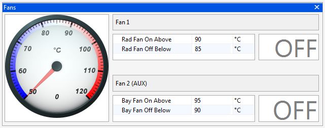
OMEM600 Tuning Manual 3v00

1     Introduction ................................................................................................................. 4

    1.1   What this manual covers .......................................................................................... 4

    1.2   How to use this manual ............................................................................................ 4

    1.3   Notation Used in This Manual .................................................................................. 4

2     Setup Procedure ......................................................................................................... 5

3     Software ...................................................................................................................... 7

4     Sensor Setup .............................................................................................................. 8

    4.1   Throttle Position Sensor ........................................................................................... 8

    4.2   MAP Sensor for Engine Load ................................................................................... 8

    4.3   Coolant Temperature sensor .................................................................................... 9

    4.4   Air Temperature sensor .......................................................................................... 10

    4.5   Barometric Pressure ............................................................................................... 11

    4.6   Road Speed Sensor ............................................................................................... 11

    4.7   Crank Sensor ......................................................................................................... 11

    4.8   Trigger Wheel ......................................................................................................... 12

    4.9   Ignition Timing Alignment ....................................................................................... 14

5     Auxiliary Inputs and Outputs ................................................................................... 15

6     Map Axes ................................................................................................................... 17

    6.1   Engine Speed ......................................................................................................... 17

    6.2   Engine Load ........................................................................................................... 17

7     Rev Limits ................................................................................................................. 20

8     Basic Fuel Setup ....................................................................................................... 21

    8.1   Battery Voltage Compensation ............................................................................... 22

                                                                                                                                     1
OMEM600 Tuning Manual 3v00
9 Ignition Setup ............................................................................................................ 24
9.1 Dwell Control .......................................................................................................... 24
10 Dashboard ................................................................................................................. 26
10.1 Tacho ..................................................................................................................... 26
10.2 Shift Light ............................................................................................................... 26
10.3 Gear dependent shift light speed ............................................................................ 26
11 Gear Recognition ...................................................................................................... 27
12 Engine Start Condition ............................................................................................. 28
12.1 Ignition .................................................................................................................... 28
12.2 Fuel ........................................................................................................................ 28
13 Idle Strategies ........................................................................................................... 30
13.1 Without air bypass idle motor ................................................................................. 30
13.2 With air bypass idle motor ...................................................................................... 31
14 Transient Conditions ................................................................................................ 36
14.1 Acceleration Fuel .................................................................................................... 36
14.2 Deceleration Fuel Cut Off ....................................................................................... 38
15 Conditions Corrections ............................................................................................ 39
15.1 Coolant Temperature ............................................................................................. 39
15.2 Air Temperature ..................................................................................................... 39
15.3 Barometric Pressure ............................................................................................... 40
16 Cold Engine Running ............................................................................................... 41
17 Oxygen Feedback ..................................................................................................... 42
17.1 Narrowband ............................................................................................................ 42
17.2 Wideband ............................................................................................................... 45
2OMEM600 Tuning Manual 3v00
18 Cooling Fans ............................................................................................................. 46
19 Knock Control ........................................................................................................... 47
20 Full Throttle Gearshift .............................................................................................. 48
21 Turbo Boost Control ................................................................................................. 51
22 Anti-lag ...................................................................................................................... 52
23 VTEC Cam Control.................................................................................................... 53
24 Alt Function ............................................................................................................... 54
25 User1.......................................................................................................................... 55
26 Launch Control ......................................................................................................... 56
26.1 Turbocharged engines ........................................................................................... 56
26.2 Non-Turbocharged engines .................................................................................... 58
27 Password ................................................................................................................... 59
3OMEM600 Tuning Manual 3v00
1 Introduction
Thank you for choosing Omex Engine Management. This manual is written to help the user through
the specifics of tuning the OMEM600 ECU. It is essential that the user reads all of the Omex
manuals before attempting to install the system and before attempting to start the engine.
Incorrect use of the Omex system could potentially lead to damage to the engine and personal
injury. If you have any doubts about fitting these parts or using the software then please contact
Omex for help.
As the system is computer based, technical support is given on the assumption that the user is able
to perform simple Windows based operations. The user will also need access to email as Omex will
nearly always require a copy of the calibration in the ECU to give support.
Omex may not be held responsible for damage caused through following these instructions,
technical, or editorial errors or omissions. If you have any doubts about fitting these parts or using
the software then please contact Omex for help.
1.1 What this manual covers
This manual covers the tuning of your Omex 600 ECU. Installation of the ECU and software use are
in-part covered, but there are separate manuals available that cover these topics in more depth.
1.2 How to use this manual
Chapter 2. Setup Procedure, runs you through a typical setup, directing you to the appropriate
detailed chapters when required.
1.3 Notation Used in This Manual
Menu commands are signified in bold type with a pipe symbol | between each level of the menu.
For example, File | Open indicates that you should click on the Open option in the File menu.
4OMEM600 Tuning Manual 3v00
2 Setup Procedure
The following is a guide to starting an engine with a new Omex ECU.
Installation
The installation of the ECU and associated hardware is covered in the ‘Installation Manual’.
Software
Follow the ‘Software’ chapter of this manual for instructions on how to connect to your ECU and
send your startup calibration.
Setup before mapping
Follow the ‘Sensor Setup’ chapter.
Follow the ‘Rev Limits’ chapter.
Follow the ‘Map Axes’ chapter (advanced users only).
Follow the ‘Auxiliary Inputs and Outputs’ chapter, though we suggest that all non-essential functions
(e.g. full throttle gearshift) are disabled until fuel and ignition mapping is complete.
For many engine configurations, the majority of these sections can be ignored as the start-up
calibration will be set to suit the standard engine. Refer to the calibration’s notes field for information
about sensors used in the calibration.
First start fuel
When attempting to start the engine for the first time you may need to change the injector scaling as
the fuel requirements, injector flowrates, and fuel pressure vary between engines. The option
Microsec/bit is a linear scaling factor. A higher number is more fuel, a lower number is less.
First start ignition timing
Follow the ‘Ignition Timing Alignment’ section of the ‘Sensor Setup’ chapter.
Main fuel and ignition mapping
Ensure before mapping that the oxygen feedback is disabled by setting Standard | OX FB | OX FB
Rate = 0.
If a road car, calibrate the injector battery voltage offsets before much mapping is done.
Map all fuel and ignition in steady state conditions.
Calibrate warm running transient fuel.
Calibrate warm engine starting fuel.
Cold starting / running setup
It is important to calibrate the cold running in the correct order as some of the tables are in effect all
of the time and so will affect the results of others.
Start engine from cold however you can (ignoring the cold cranking fuel for now), and calibrate the
Coolant Fuel trim table and the Accel Coolant trim table. The Coolant fuel trim table is used for
steady-state engine running, and the Accel Coolant trim table for increased acceleration fuel whilst
cold. Refer to the relevant sections for further advice on this.
5OMEM600 Tuning Manual 3v00
When the cold running is complete, you can calibrate cold starting. Refer to the relevant section for
advice on this.
6OMEM600 Tuning Manual 3v00
3 Software
Installing the software
Run SetupMAP4000.x.xx.xx.exe and follow the onscreen instructions.
Connection port
The ECU requires an RS232 serial connection. Desktop PCs and older laptops will have 9pin D
shaped ports on them marked COM for this type of communication. If you have this port then this is
the best to use for communication with the ECU. If your PC does not have one of these ports then
you will need to use an adapter. We suggest using the USB to RS232 adapter from ‘ATEN’ as the
software has been specifically designed for this adapter.
Connecting to the ECU
Ensure that if you are using an adapter, the drivers software from the adapter manufacturer has
been installed.
Join the data lead between the ECU and the PC
Open MAP4000 from the ‘Start bar’
ECU | Connection Setup and select your port from the list
ECU | Connect
Ignition ON (do not crank the engine)
The ‘Receiving Calibration’ bar will start moving across. When completed, you are connected to
the ECU.
Sending the startup calibration to the ECU
It is not possible to start a new calibration from File | New. Please contact Omex for a
suitable start-up calibration.
Save the start-up calibration from the start-up disk or email to the hard-drive in the location
Documents\OMEX\MAP4000\Calibrations. (note that this folder is only created when MAP4000
is opened for the first time so you must have opened MAP4000 on this PC before)
Connect to the ECU as described in the above section.
ECU | Send new calibration
Ignition ON (do not crank the engine)
Select your start-up calibration and press ‘open’
When the calibration has been sent to the ECU cycle ignition power OFF / ON
7OMEM600 Tuning Manual 3v00
4 Sensor Setup
4.1 Throttle Position Sensor
The parameter TPS raw gives the raw number output of the sensor which is scaled by options TPS
min and TPS max to give a throttle that works between 0 and 100%. To calibrate;
A live reading is shown for TPS raw. TPS raw will be between 0 and 255. The throttle position
sensor can often be rotated by the user. If so, the position should be set so that the sensor
never reaches 0 or 255 during its closed throttle to open throttle movement. It is preferable to
have the sensor set so that the values do not go close to either extreme. Typically a value of
approximately 20 at the idle position will give an acceptable value at WOT (wide open throttle).
The number for TPS raw at WOT needs to have 1 added to it, then be inputted to the options
box as TPS max (i.e. if TPS Raw is 220, then input 221). The number for TPS raw at the idle
position needs inputting to the options box as TPS min.
The Autozero options allow the ECU to automatically re-learn the idle position of the throttle sensor
every time the ECU is turned on. 0 disables this feature.
4.2 MAP Sensor for Engine Load
If you are using MAP for engine load sensing then set MAP for Load ON.
MAP min and MAP max should be 0 and 255. Do not change these unless instructed to by Omex.
MAP Cal is the the time over which the ECU averages the MAP sensor input. Measured in internal
units. Typically 12.
As standard, the fuel map and ignition map will show load values of 0-100KPa. This is not KPa, this
is simply 0-100% of the range of the sensor. It is possible to tell the ECU what range the sensor has
so that you can read the true KPa value on the maps.
Load Scalar The multiple of 1 that describes the theoretical 0-5V full scale of the
sensor.
Load offset Most MAP sensors do not have 0V at 0KPa, they have a slight offset.
This option describes the offset.
8OMEM600 Tuning Manual 3v00
Omex have the values for the sensors sold by Omex. If you want to calibrate your own sensor then
either find the voltage output information (total scale, and offset) from the manufacturer, or follow
this procedure;
Select a suitable start point for Load Scalar to suit your sensor e.g. for a nominally 2bar sensor,
enter 2
Note the current value for MAP as Load
Change the pressure at the sensor by a known amount using a vacuum pump
Ignoring the absolute value, adjust Load Scalar until the correct change in value is shown by
MAP as Load to suit that pressure change e.g. if you have reduced the pressure by 50kPa,
then adjust Load Scalar until MAP as Load shows 50kPa less than it did before the pressure
change was made
Remove the pressure change and try the above again. As this is an iterative procedure you may
need to do it several times before the correct change is shown on the ECU
Remove any pressure changes from the sensor and adjust Load offset until MAP as Load
shows the current barometric air pressure.
4.3 Coolant Temperature sensor
The coolant temperature sensor used by the Omex ECU is a resistive sensor. The raw output of this
sensor is calibrated in the ECU to give the information in a more usable form, oC. Sensors are
calibrated in the Coolant Temp Sensor table. The values for many sensors are known but you may
need to calibrate your sensors. It is essential that these sensors are calibrated correctly as many
functions are temperature based.
To calibrate a sensor;
Place the sensor and a thermometer in a kettle or pan of water
9OMEM600 Tuning Manual 3v00
The ECU will highlight the current raw input value from the sensor along the upper line of the
table. Below this input value, enter the current thermometer reading in degrees centigrade.
Heat the water. As the temperature increases, repeat the temperature readings.
When the water is fully heated, repeat the process as the water cools
Using the graph view, smooth the curve to remove any mistakes, and extrapolate to
unobtainable temperatures.
Coolant Fail Low and Hi are the failure points of the sensor and should be set to just within the
reading limits of the sensor.
Example- If the lowest temperature in the sensor table is –25 then Coolant Fail Low should be set
1 higher at –24. If the highest temperature in the sensor table is 125 then Coolant Fail Hi should be
set 1 lower to 124. Coolant Temp Default is the temperature to which the input defaults if the
sensor goes into failure.
4.4 Air Temperature sensor
The air temperature sensor used by the Omex ECU is a resistive sensor. The raw output of this
sensor is calibrated in the ECU to give the information in a more usable form, oC. Sensors are
calibrated in the Air Temp Sensor table. The values for many sensors are known but you may
need to calibrate your sensors. It is essential that these sensors are calibrated correctly as many
functions are temperature based.
To calibrate your sensor, see the calibration of the coolant temperature sensor.
Air Temp Fail Low and Hi are the failure points of the sensor and should be set to just within the
reading limits of the sensor.
Example- If the lowest temperature in the sensor table is –25 then Air Temp Fail Low should be set
1 higher at –24. If the highest temperature in the sensor table is 125 then Air Temp Fail Hi should
10OMEM600 Tuning Manual 3v00
be set 1 lower to 124. Air Temp Default is the temperature to which the input defaults if the sensor
goes into failure.
4.5 Barometric Pressure
As the air pressure changes, so does the amount of oxygen per volume of air. Changes in most
countries are relatively little, but if driving in large mountain ranges, these changes can be
significant. The Baro On option should only be checked if the engine is being mapped and run with
a sensor connected. If you wish to use a baro sensor it must be connected and set up before
mapping. The options list has values for calibrating the pressure sensor. Contact Omex for setup
numbers for your sensor.
4.6 Road Speed Sensor
The road speed sensor is only required if you wish to use gear dependent shift light speeds. The
input should be a pre-differential driven wheel input e.g. propshaft rpm.
The road speed sensor can only be calibrated once the engine is running.
The option Road Speed M is a scalar and should be adjusted until the parameter Road Speed
reads the actual road speed.
Rd Spd Falling Edge and Rd Spd Rising Edge specify the edge of the input waveform from the
sensor to use as the significant edge. Typically Rd Spd Falling Edge.
Road speed can be displayed as either mph or kph. To adjust the units used go to Configure |
Units/Scaling | Road Speed Units.
4.7 Crank Sensor
The crank sensor input can be from either a Magnetic Variable Reluctance (MVR) sensor or a Hall
Effect sensor. The two types of sensor require different hardware on the ECU board, so are selected
by physical jumpers. This is covered in the installation manual.
Software changes must be made to suit the sensor type.
11OMEM600 Tuning Manual 3v00
MVR
The crank sensor high and low gain settings allow a user definable change point for high sensitivity
to allow for low magnetic crank sensor outputs at low engine speeds. Typically the values are just
above idle speed.
Magnetic sensors can use either the rising or falling edge of the generated waveform. If the edge is
incorrect then the engine will misfire at some point in the engine speed range. There is also the
possibility that if the edge is incorrect on a magnetic sensor of the ignition timing on the engine
deviating from the ignition timing calculated by the ECU as the engine speed changes. To find the
correct edge either see which edge does / does not produce ignition timing changes, or using an
oscilloscope to look at the waveform. If the signal falls through the missing tooth section use Crank
Rising Edge, and if it rises through the missing tooth section use Crank Falling Edge.
Hall Effect
Hall effect sensors require values of 0 for the high and low gain settings as their output is the same
amplitude regardless of engine speed.
Hall Effect sensors can use either the rising or falling edge, though typically the falling edge would
be used.
4.8 Trigger Wheel
The pattern of teeth on the crank or flywheel that the crank sensor faces is known as a trigger
wheel. The pattern is evenly spaced teeth with missing or extra teeth as reference points. As
different manufacturers use different trigger patterns, the ECU is programmable to suit. The
information required in the ECU for many of the popular patterns is already known, some of which
are listed below. If you have a different pattern on your engine please contact Omex for advice.
It is very easy to make an engine run, but not run properly by incorrectly entering these
options and tables. If possible please contact Omex for a calibration aspect or email an
existing calibration to Omex to be changed to a different trigger pattern.
36-1
12OMEM600 Tuning Manual 3v00
Tooth Control table:
0 1 2 3 4 5 6 7 8 9 10 11 12 13 14 15 16 17 18 19
5 4 4 5 4 4 5 4 4 5 4 4 5 4 4 5 4 4 5 4
20 21 22 23 24 25 26 27 28 29 30 31 32 33 34 35 36 37 38 39
4 5 4 4 5 4 4 5 4 4 5 4 4 5 4 3 3 3 3 3
40 41 42 43 44 45 46 47 48 49 50 51 52 53 54 55 56 57 58 59
3 3 3 3 3 3 3 3 3 3 3 3 3 3 3 3 3 3 3 3
60-2
Tooth Control table:
0 1 2 3 4 5 6 7 8 9 10 11 12 13 14 15 16 17 18 19
5 4 4 4 4 5 4 4 4 4 5 4 4 4 4 5 4 4 4 4
20 21 22 23 24 25 26 27 28 29 30 31 32 33 34 35 36 37 38 39
5 4 4 4 4 5 4 4 4 4 5 4 4 4 4 5 4 4 4 4
40 41 42 43 44 45 46 47 48 49 50 51 52 53 54 55 56 57 58 59
5 4 4 4 4 5 4 4 4 4 5 4 4 4 4 5 4 4 3 3
Rover K-Series (late)
Tooth Control table:
0 1 2 3 4 5 6 7 8 9 10 11 12 13 14 15 16 17 18 19
4 4 5 4 4 5 4 4 5 4 4 5 4 5 4 5 4 4 5 4
20 21 22 23 24 25 26 27 28 29 30 31 32 33 34 35 36 37 38 39
4 5 4 4 5 4 4 5 4 5 4 5 3 3 3 3 3 3 3 3
40 41 42 43 44 45 46 47 48 49 50 51 52 53 54 55 56 57 58 59
3 3 3 3 3 3 3 3 3 3 3 3 3 3 3 3 3 3 3 3
13OMEM600 Tuning Manual 3v00
4.9 Ignition Timing Alignment
The ECU recognises the engine position by a missing or extra tooth on a pattern of evenly spaced
teeth. Different manufacturers have this reference in a different place on the trigger wheel so the
ECU needs to have adjustment for this. The numbers are known for most manufacturers and will be
set in the start-up calibration but if they are unknown or if you are using an Omex external 36-1
wheel, you will need to find this value yourself. To find this value you will need a strobe light and an
accurate TDC mark on the engine.
Hold the engine at 2000-3000 rpm (ie out of the idle condition where the ignition timing is stable)
Check the engine speed shown on the strobe light. Most strobe lights will see the wasted spark
on DIS systems and so will show double engine speed and so also double ignition timing. If this
is the case then halve all ignition timing figures shown on the strobe light.
Check the ignition timing with a strobe light and compare this number to the number in Target
Timing.
If the engine is retarded compared to Target Timing (the strobe light shows a lower value) then
advance the engine. If the engine is advanced compared to Target Timing (the strobe light
shows a higher value) then retard the engine. The larger buttons make larger changes, the
smaller buttons make smaller changes. The Target Timing on the PC will not change, but the
timing mark on the engine will move, so each adjustment will require the strobe light resetting.
Repeat these changes until the strobe light timing figure agrees with the Target Timing figure.
If you cannot get the engine to start and believe this is because the ignition timing is incorrect then
you can perform the above tests whilst cranking the engine. Timing lights will not work correctly
during normal cranking as the engine speed varies so much due to the compression of each
cylinder. Therefore the spark plugs should be removed (to remove compression), put back into the
HT leads, and placed onto an earthed part of the engine, then the process documented above can
be followed but at cranking speeds. When this is done and you get the engine started, it should be
repeated at normal running speeds.
14OMEM600 Tuning Manual 3v00
5 Auxiliary Inputs and Outputs
Many functions have dedicated pins, but there are also 3 auxiliary inputs and 4 auxiliary outputs that
may be assigned to whichever functions are required in your installation.
Each function is assigned to an input or output. Each input or output may only be assigned to one
function.
For details of how to wire the auxiliary inputs and outputs please see the installation manual.
The drop-down menus have many options for which inputs and outputs can be selected. Use only
the AUX options.
Inputs
For a function to be always active (sometimes useful with the Alt function) select Switch is Always
ON. Main Relay Input should always be set to Switch is always ON.
AUX IN 1 is satisfied by the wire going to earth and so the input used is AUX IN 1 OFF. AUX IN 2
and AUX IN 3 are satisfied by the wire going to 12V and so the input used is AUX IN 2 ON or AUX
IN 3 ON.
Switch outputs
PWM outputs
15OMEM600 Tuning Manual 3v00
The PWM outputs may only be assigned to AUX OUT 1.
The base frequency of this PWM output is 250Hz. The option PWM1256 divider allows this
frequency to be reduced if the PWM device requires this. Values are shown below.
Frequency (Hz) Divider
250 1
125 2
84 3
62.5 4
50 5
42 6
36 7
32 8
28 9
25 10
16OMEM600 Tuning Manual 3v00
6 Map Axes
6.1 Engine Speed
All maps (fuel, ignition etc) use the same rpm axis. You can adjust this axis on any of the maps and
it will affect all of them. Typically the RPM axis would have a value towards stall as the first site
(450rpm), a site just below the target idle speed, a site on the target idle speed, a site just above the
target idle speed, then the rest of the sites evenly spaced to complete the engine speed range, the
final site being just above the rev limit. On some engines it may be useful to increase the density of
sites around areas where the fuel and ignition requirements change rapidly e.g. where an engine
‘comes onto cam’.
6.2 Engine Load
There are several choices for engine load reading;
Normal Aspirated
TPS for load (preference due to giving best throttle response and easy mapping)
MAP for load
Turbocharged / Centrifugal Supercharged
MAP for load
Boost Correction fuel mapping with MAP for load ignition mapping
Positive Displacement Supercharged
TPS for load
MAP for load
17OMEM600 Tuning Manual 3v00
TPS for load
Select this mode by ensuring Standard | Sensor Setup | MAP Sensor | MAP for load = OFF. All
options found in Advanced | Boost Correction must be OFF. The load axis will read kPa but this is
actually 0-100% throttle. All maps (fuel, ignition etc) will use the same load axis. You can adjust this
axis on any of the maps and it will affect all of them. Typically, the sites would be evenly spaced
through the throttle range, maybe with closer sites at light throttles.
MAP for Load
Turn on MAP for load and scale the MAP sensor as described in the earlier ‘MAP sensor for engine
load’ section of this manual. . All options found in Advanced | Boost Correction must be OFF. All
maps (fuel, ignition etc) will use the same load axis. You can adjust this axis on any of the maps and
it will affect all of them. The load axis of the map should have the lowest site as the minimum MAP
value on overrun, the next site up is the MAP value at warm idle, the top site should be set to just
above the maximum manifold pressure that will be run by the engine, then the sites in between
evenly spaced and maybe more densely placed below 100kPa than above.
18OMEM600 Tuning Manual 3v00
Boost Correction fuel mapping with MAP for load ignition mapping
Ensure MAP for Load is ON and the MAP sensor is scaled as described in the sensor setup section
of this manual. Set Advanced | Boost Correction all options ON.
The Ignition Map load axis will be MAP for load. This should have the lowest site as the minimum
MAP value on overrun, the next site up is the MAP value at warm idle, the top site should be set to
just above the maximum manifold pressure that will be run by the engine, then the sites inbetween
evenly spaced and maybe more densely placed below 100kPa than above.
The Fuel Map load axis will be marked Throttle Angle. Typically, the sites would be evenly spaced
through the TPS range, maybe with closer sites at light throttles.
The fuel trim at any given manifold pressure is set in the Boost Fuel Correct Table.
The correction should be set to 0 at 100kPa.
19OMEM600 Tuning Manual 3v00
7 Rev Limits
The Fuel Cut RPM table and Ign Cut RPM table allow differing rev limits based upon throttle
position for when using anti-lag. If you are not using anti-lag, set all of the throttle positions in the
table to the same engine speed. An example of a 6000rpm limit is as follows.
At this engine speed, the soft cut will be invoked. If the engine speed is exceeded by 50 rpm, then
the hard cut is invoked. The Fuel Cut RPM Table should be set to an engine speed that is higher
than the ignition cut rev limit.
A second rev limit can be imposed when the engine is below a specified temperature.
Lo Limit Below Cool the temperature below which the cold rev limit is set
Lo Limit Offset the reduction in rev limit when rev limit coolant is satisfied
20OMEM600 Tuning Manual 3v00
8 Basic Fuel Setup
The amount of fuel injected each cycle is dependent on the time the injector is open. This time
period (or pulse width) is calculated by the ECU using the values found in the main fuel map and all
of the modifiers such as transient fuel, cold start enrichment etc.
On the main fuel map, at each intersection of an engine speed site and an engine load site there is a
grid value. This is the VE value and is directly proportional to the pulse width and therefore the
amount of fuel injected.
These values are determined by running the engine on a dynamometer at each obtainable point and
adjusting the VE values to obtain optimum performance. (ie mapping the engine).
If the engine is running at an exact engine speed site and an exact engine load site then the VE
value at the intersection of these two sites will determine the amount of fuel injected. If running at a
condition where it is not exactly on a mapped site, the ECU interpolates between the nearest sites.
The fuel pulsewidth from the main fuel map is calculated as follows;
Base fuel pulsewidth = raw (map) value x Microsec/bit
As a starting point it is quite acceptable to set Microsec/bit to 50. This will give a very good starting
point for most engine setups. Once a sample full throttle point around maximum torque has been
trial mapped, the Microsec/bit can be adjusted to give a maximum fuel map setting of 200 or so. If
working from a reasonable start-up calibration, set the engine to be very slightly rich overall by
adjusting Microsec/bit, then map sites from this point. Once a rough calibration is made, the fuel
map can be rescaled (see below) to give better resolution.
Fuel Sync is the overall injection start point delay measured in internal units, A change in value of 1
is a change in start point of 30 crank degrees. This number can be changed to give the best
emissions or power.
Fuel maps have six additional commands in the pop-up menu. Three View commands change the
units the map is displayed in. The other three commands alter the fuel map to achieve better
scaling.
View commands
Available by a right-click on the fuel map, a pop-up menu gives three view commands to select the
units the fuel map is displayed in. Only one view command can be checked at any one time.
View raw - Shows the raw value of the map as stored in the ECU. These are the values that
should used during engine mapping. It has a range of 0 to 255. When selected, the caption of
the map window shows Raw.
View pulse width - Shows the actual injector pulse width in milliseconds before any
modifications. When selected, the caption of the map window shows Pulse Width. This view
mode should be used for reference only, not for inputting data whilst mapping.
View duty cycle - Shows the percentage of time that the injectors are actually open. When
selected, the caption of the map window shows Duty Cycle. In order for MAP4000 to correctly
calculate the duty cycle, when View duty cycle is selected, it prompts for the number of
injections per engine revolution. With the 600 ECU on a 4cyl 4stroke engine, select 1. This view
mode should be used for reference only, not for inputting data whilst mapping.
21OMEM600 Tuning Manual 3v00
Fuel map rescaling
Available by a right-click on the fuel map, a pop-up menu gives commands for altering the fuel map;
Rescale fuel map - This changes the fuel map values and the option Microsec/bit such that
the pulse width for every site remains constant but the maximum value in the fuel map is
adjusted to 240. This therefore gives near maximum resolution, with an amount of headroom
should the maximum torque point require a longer pulsewidth later in the tuning.
Optimize fuel map – Rarely used. Do not use this option on an engine that is already mapped.
This changes the fuel map values, the option Microsec/bit and the option LD0MPC such that
the resolution is increased throughout the fuel map by non-linearising the raw values. This is
particularly useful when calibrating fuelling for low load sites and stable idling on high boost
engines.
Change injectors / pressure - This allows the fuel map to be rescaled to accommodate a
change in injector size and/ or fuel line pressure. When selected, the Resize Injectors dialog is
shown:
To use this dialog;
Enter the specification of your fuel system before modification and after modification and MAP4000
will alter your fuel related maps and tables to suit.
8.1 Battery Voltage Compensation
An injection period is made up physically of 2 time periods. The end period is when the injector is
open and flowing fuel, and the first period is when the injector is opening its valve and there is no
flow of fuel. At low injector durations, this period where the injector is reacting but not flowing fuel
can be significant.
This time period of no flow varies in length with battery voltage and with fuel pressure. This also
varies between injector models. Were an engine to run at a constant voltage, then there would be no
problems as the injector reaction time would be a constant length. However, the injectors do see a
varying voltage so the ECU needs to allow for this varying period of no fuel flow, and as all types of
22OMEM600 Tuning Manual 3v00
injector react differently, it needs to be told this information by the user. The information is held in
the ECU in the Battery Comp table. Standard | Conditions Corrections | Fuel | Battery Voltage.
The battery voltage compensation data can usually be supplied by the injector manufacturers. For
example, the Weber IW 058 injector data for 3bar fuel pressure,
Battery Volts Offset time mSec
8.0 2.03
10.0 1.22
12.0 0.81
14.0 0.56
16.0 0.39
The Omex ECU can not take the data in the form of offset time in msec, it instead requires the table
to hold the data as a number between 0 and 255 which is then scaled. If using offsets from injector
manufacturers simply multiply the offset time, usually stated in mSec, by 100.
Battery Volts Battery Comp
8.0 203
10.0 122
12.0 81
14.0 56
16.0 39
The missing values for odd voltages are best blended using the graphical display.
If this information is unavailable for your injector, then you will need to find these values yourself.
Connect a power supply to run the injectors and ECU at variable voltages
Set the voltage to one of the sites in the Battery Comp Table near to the normal running voltage
of the vehicle, typically 14V.
Map an area of the fuel map to a constant AFR (this area should be out of idle so the engine is
steady)
Change the voltage of the power supply to one of the voltages on the Battery Comp table
The lambda reading may change. If so, change this voltage’s value in the Battery Comp table
to return the lambda to the original reading
Repeat this for all of the possible voltages
If a power supply is unavailable, then an attempt can be made to bring down the voltage in road cars
by turning on lights, heater blowers etc.
23OMEM600 Tuning Manual 3v00
9 Ignition Setup
Ignition timing is controlled by a map of numbers where a positive number is timing before TDC (top
dead centre), and negative numbers after TDC. The vertical axis for engine load will always show
kPa as the units. If using throttle position for load this is not true, and is actually % throttle.
As the reference point (missing or extra tooth) on a crank trigger wheel varies rotationally between
manufacturers and between individual‘s installations of trigger disks, the ECU needs to be told
where the reference point is. The option Timing Alignment describes this and can be adjusted to
suit each trigger wheel type. See the ‘Setup Procedure’ chapter for information on how to find the
correct value for your engine. The correct numbers are known for many popular manufacturers.
Please contact Omex for advice.
9.1 Dwell Control
The coil dwell time is set by option Coil Dwell Factor. This is a unitless value typically 20 - 25 for a
DIS coil pack. Charge times can be varied with respect to battery voltage and engine speed using
the Dwell vs Battery table and Dwell vs Speed table. Setting these table values to 100% gives a
constant dwell time.
24OMEM600 Tuning Manual 3v00
The options Dwell max and Dwell min are the limits of dwell time regardless of calculated values
from the tables and coil factor option. These limits are measured in internal units. Contact Omex if
you want to change these values.
When running the engine, the current dwell time can be monitored using parameter Dwell Time.
Calibrating Dwell Time
A startup calibration from Omex will have typical values for charge time alterations against battery
voltage and engine speed so you will normally only need to adjust the Coil Factor. You should use
the lowest value that still makes the greatest torque output from the engine.
25OMEM600 Tuning Manual 3v00
10 Dashboard
10.1 Tacho
The frequency of pulses for the tacho is set by the option Tacho Teeth. Adjust this number until the
tacho reads the correct engine speed. The correct setting for a 4cylinder tacho is 3.
10.2 Shift Light
If using a single shift light engine speed for all gears then the engine speed at which the light is
turned on is set by the option Shiftlight On RPM;
10.3 Gear dependent shift light speed
For this control a road speed sensor must be fitted and calibrated, and gear recognition must be
calibrated.
26OMEM600 Tuning Manual 3v00
11 Gear Recognition
Option Gear Control must be set ON to enable to gear recognition. From the Engine Speed and the
Road Speed inputs, the ECU is able to calculate the current gear ratio. This information is displayed
in parameter Gear Ratio. The gear ratio for each gear is then input to the Gear Ratio table. Each
gear has a high and low limit for the gear ratio to account for clutch slip etc. The low limit for 1st gear
is input above 1, and the high limit is input above 1.5, and so on.
Once the above table is completed, the ECU knows what gear the car is in and displays this in
parameter GEAR.
27OMEM600 Tuning Manual 3v00
12 Engine Start Condition
During cranking the fuel and ignition are not controlled by the main fuel and ignition maps, but
instead by separate tables and options.
The cranking condition is defined by the engine speed options Min RPM and Start Exit RPM. Min
RPM is the engine speed at which the engine is considered to start cranking (typically 50 rpm), and
Start Exit RPM is the engine speed above which the engine is considered to be under normal
running ie no longer cranking (typically 400rpm)
12.1 Ignition
Whilst cranking, the ignition timing is determined by the Start Ignition option. This is set in degrees
and would normally be a low value eg 2 degrees.
12.2 Fuel
28OMEM600 Tuning Manual 3v00
Start Fuel Throttle Table – This is the amount of fuel injected, dependent on throttle position, while
the engine is starting. This value is VE (same as the main fuel map) so is multiplied by Microsec/bit
to give the fuel pulsewidth.
Start Fuel Coolant Table – Extra percentage of fuel added to the Start Fuel Throttle due to
temperature.
Start Fuel Decay Table – This determines how quickly the additional start fuel decays over time.
This is a linear decay in seconds after cranking commences.
Start Fuel Pulse Table- This is an extra single injection of fuel that is injected at the very start of
cranking. This value is VE (same as the main fuel map) so is multiplied by Microsec/bit to give the
fuel pulsewidth.
Setting-up start fuel
It is important to note that the Coolant Fuel Trim table is always active, even under cranking
conditions, and so the cold engine running must be completed before the cold starting can be fully
calibrated.
The Start Fuel Throttle table very rarely requires changing from Omex’s standard values. The
standard values have 0 fuel at 100% throttle, allowing a flooded engine to be cleared by using full
throttle whilst cranking.
In general, an engine that has too much starting fuel will start and then immediately stop again. If
there is a very large excess of fuel, the engine may even ‘kick back’ as if it were too far advanced on
the ignition. An engine with too little starting fuel will crank for a long time before the engine will start.
Both of these situations call for a change to both the Start Fuel Pulse table, and the Start Fuel
Coolant table. If the engine starts but will not rev freely for the first few seconds of engine running,
then the Start Fuel Decay table usually requires adjusting.
29OMEM600 Tuning Manual 3v00
13 Idle Strategies
The 600 series ECU can control idle using spark scattering, push/pull motors and stepper motors.
The idle condition is entered by the options Idle on Below RPM, and Idle On Throttle. The engine
must be below both of these values to enter idle.
The normal warm target idle speed that the ECU attempts to maintain is set by Idle FB Target RPM.
A high idle will be required in some conditions. The ECU can set a high idle speed based on coolant
temperature (Idle Hi Below Cool), or as engine speed drops towards idle to give a ‘soft’ return to
idle (Idle Hi Time and Idle Hi Decay). The target idle increase above the normal idle speed for high
idle is Idle Hi FB Target+. When returning to the idle condition the target speed is the ‘Hi’ speed for
Idle Hi Time then reduced to the normal idle speed over a period of time set by Idle Hi Decay.
13.1 Without air bypass idle motor
If there is no idle motor on the engine then just the scatter spark idle is used.
The Idle Scatter Spark Table shows the change in ignition timing based upon rpm away from the
target engine speed. When the engine speed is higher than target negative values are required to
30OMEM600 Tuning Manual 3v00
decrease the idle rpm, and when the idle is lower than target positive values are required to increase
the idle rpm. As the engine moves further away from the target speed, the numbers should increase.
Setting idle scatter control
Turn the scatter spark control off by setting Idle On Below RPM to 100rpm so that the engine
will not enter the idle condition.
With the engine warm set the natural idle (through adjusting air bleed screws or if necessary,
the throttle stop, remembering that if the throttle stop is moved, TPS min must be reset) to
approximately 150rpm higher than the target idle speed.
Turn the scatter spark idle control back on by resetting the Idle On Below RPM option to its
previous value.
Blip the throttle and the engine speed should return to the Idle FB Target RPM value.
As the engine is being given more air than is required to idle the engine when warm it retards the
ignition whilst in the idle condition to maintain the target engine speed. When the engine is cold it
requires more air to idle and so it benefits from the extra air, the ignition is advanced whilst in the
idle condition, and the engine has an improved cold idle speed.
Setting Hi Idle
With scatter spark control you simply set the Hi Idle options. As there is no idle motor to give the
engine extra air, the ECU will attempt to hold the Hi Idle speed, but will not be able to match it when
the engine is cold. Therefore, the high idle is only really used to give a gentle return to idle.
13.2 With air bypass idle motor
There are three types of air bypass motor; 2 wire spring return, 3 wire push/pull, and stepper motor.
Idle Duty Min is the duty cycle below which the idle motor does not flow any air.
Idle Duty Max is the duty cycle above which the idle motor does not flow extra air.
The Idle Duty Coolant table gives the % opening of the idle motor required at each temperature to
achieve the base target idle.
The Idle Duty RPM table is a modifier based on engine speed for if the engine speed moves below
the target idle ie anti-stall. The target idle speed should have a modifier of 0. Engine speeds well
below target should have a large positive number to open the idle motor to stop the engine stalling.
The example below is typical for a 1000rpm idle.
31OMEM600 Tuning Manual 3v00
The idle is then fine-tuned and maintained by the feedback loop. Idle FB- max and Idle FB+ max
are the feedback limits for the idle motor. The update rate of this feedback loop is set by Idle FB
Rate. This would typically be 40ms with a stepper motor or 200ms with a PWM device.
The Idle Fuel table is required for engines that are using air bypass with throttle position as the
main load sensor. On TPS load based engines, the load sensor (the TPS) does not measure the
extra air flow due to the opening of the idle motor, so does not compensate with extra fuel in the
main fuel map to maintain the target lambda (air/fuel ratio). An oxygen sensor cannot make
adjustments to the fuelling fast enough to cope with these changes. This table allows a fuel trim
based on idle motor duty to maintain a constant lambda value. This is not required for MAP based
systems so would be set to 0 in this case.
Testing correct operation of a 2 wire idle motor
Remove the idle motor from the engine.
Ensure that the idle motor has a constant power supply. If powered from a relay controlled by
the ECU you will need to temporarily ‘bridge across’ this relay to give the idle motor constant
power.
In the Idle Duty Coolant Table find the current engine temperature and set that site and the
sites either side to 0 which should close the valve. Set the sites to 100 and the valve should
move to fully open. Some idle motors (usually Bosch parts) are slightly open when at a value of
0, then close at about 30, then start to open again until fully open at 100. The value at the
closed position must be inputted to Idle Duty Min.
Testing correct operation of a 3 wire idle motor
Remove the idle motor from the engine.
Ensure that the idle motor has a constant power supply. If powered from a relay controlled by
the ECU you will need to temporarily ‘bridge across’ this relay to give the idle motor constant
power.
In the Idle Duty Coolant Table find the current engine temperature and set that site and the
sites either side to 0 which should close the valve. Set the sites to 100 and the valve should
move to fully open. If the opposite happens i.e. the valve is fully open at a value of 0 then either
swap the 2 IDLE wires at the idle motor connector or swap the Idle PWM1 out and the Idle
PWM2 out.
Some idle motors (usually Bosch parts) are slightly open when at a value of 0, then close at
about 30, then start to open again until fully open at 100. The value at the closed position must
32OMEM600 Tuning Manual 3v00
be inputted to Idle Duty Min.
Testing correct operation of a 4 wire stepper motor
Turn ignition off.
Remove the stepper motor from the engine.
Hold the stepper motor with the plunger facing very close (approximately 5mm) to a hard object.
Ignition on. The stepper motor’s plunger should push outwards for approximately 1 second then
retract slightly. As it pushes out you must resist this by pushing it against a hard surface else the
plunger can fall off.
If the opposite happened i.e. the plunger retracted for a second, then pushed outwards slightly,
either swap the IDLE1 and IDLE2 wires at the stepper motor or swap the setting of Idle1
Stepper Out and Idle2 Stepper Out.
Setting air bypass idle control on MAP for load engines
As the idle motor opens and closes, the manifold pressure changes and so the position on the main
fuel maps moves, meaning the fuel requirement changes will be compensated for by the main fuel
map. Therefore, ensure that the Idle Fuel table is set to 0 throughout. Ensure that all Fuel Map
sites around idle (including those towards stall) are correctly calibrated before attempting this setup
for the final time.
Turn the scatter spark control and motor feedback control off by setting Idle on below RPM to
100rpm so that the engine will not enter the idle condition.
Set Idle Hi FB Target + to 0 so that the engine always has the same target idle speed.
If there is an adjustable air bleed screw or an adjustable throttle stop, set all warm temperatures
in the Idle Duty Coolant table (typically above 60degrees) to 0, then with the engine warm set
the natural idle to 100 or 200rpm below the target idle speed using the throttle stop or air bleed
screw (note that if you move the throttle stop you must reset TPS min), then increase all hot
temperatures in the Idle Duty Coolant table to a value which allows the engine to idle at the
target idle speed. If there is no mechanical idle adjustment then set all hot temperatures in the
Idle Duty Coolant table to a value which allows the engine to idle at the target idle speed.
Turn the scatter spark control and motor feedback control back on by resetting the Idle on
below RPM option to its previous value. (typically 500rpm above the normal target idle speed).
Blip the throttle and the engine speed should return to the Idle FB Target RPM value.
Follow the Setting Hi Idle instructions below.
During cold running setup of the fuelling, you will also need to adjust the Idle Duty Coolant table at
each temperature to ensure that the feedback controls have to do as little work as possible. As a
start point set all cold temperatures to 10% higher than the warm temperatures. The feedback work
can be seen in parameter Idle Set. If Idle Set is a positive number then increase the current value in
the Idle Duty Coolant table, or if negative, then reduce it.
Setting air bypass idle control on TPS for load engines
On TPS load based engines, the ECU does not measure the extra air flow due to the opening of the
idle motor, so does not compensate with extra fuel in the main fuel map to maintain the target
lambda (air/fuel ratio). An oxygen sensor cannot make adjustments to the fuelling fast enough to
cope with these changes. The Idle Fuel table allows a fuel trim based on idle motor duty to maintain
a constant lambda value. To set this table correctly, the engine must be held at the idle target speed
whilst the engine is put under varying loads to alter the opening of the idle motor. This can be
achieved through the use of a rolling road to apply the load, or simply by holding the brakes of the
vehicle and gently releasing the clutch to load the engine. The table should then be altered to
provide the extra fuel required to maintain a constant lambda value.
1. Get the engine to normal running temperatures
2. Set Idle Hi FB Target + to 0 so that the engine always has the same target idle speed.
3. Set Idle FB+ Max and Idle FB- Max both to 0.
33OMEM600 Tuning Manual 3v00
4. Set the whole of the Idle Scatter Spark Table to 0 (noting the values in this table as you will
need to re-enter them later)
5. Set the whole of the Idle Duty Fuel Trim Table to 0.
If there is an adjustable air bleed screw or an adjustable throttle stop;
6. Set all warm temperatures in the Idle Duty Coolant table (typically above 60degrees) to 0, then
with the engine warm set the natural idle to approximately 250rpm below the target idle speed
using the throttle stop or air bleed screw (note that if you move the throttle stop you must reset
TPS min). Ensure that the engine is running at the correct AFR as the wrong AFR will make the
engine run slowly. Change the fuelling in the main Fuel Map as required to maintain the correct
AFR.
7. Set the whole of the Idle Duty Fuel Trim Table to 30%
8. Increase all hot temperature values in the Idle Duty Coolant table to a value which allows the
engine to idle at the target idle speed whilst simultaneously adjusting the fuel map to achieve
the correct AFR at the idle speed.
9. Ensure that the main Fuel Map is calibrated correctly down to stall speeds and at both closed
throttle and the first site above closed throttle. This is best achieved through loading the engine
on the dyno. Typically, as the engine goes towards stall speeds, there is a large increase in
fuelling requirements.
10. In the Idle Duty Coolant Table, set various openings of the idle motor from 0-100%, load the
engine on the dyno to hold (approximately) the target idle speed, then adjust the Idle Duty Fuel
Trim Table to maintain the correct AFR.
11. Return all warm temperature values in the Idle Duty Coolant Table to a value that maintains
the target idle speed.
If there is NOT an adjustable air bleed screw or adjustable throttle stop;
6. Set the whole of the Idle Duty Fuel Trim Table to 30% and set all hot temperatures in the Idle
Duty Coolant table to a value which allows the engine to idle at the target idle speed. Ensure
that the engine is running at the correct AFR as the wrong AFR will make the engine run slowly.
Change the fuelling in the main Fuel Map as required to maintain the correct AFR at the idle
speed.
7. Ensure that the main Fuel Map is calibrated correctly down to stall speeds and at both closed
throttle and the first site above closed throttle. This is best achieved through loading the engine
on the dyno. Typically, as the engine goes towards stall speeds, there is a large increase in
fuelling requirements.
8. In the Idle Duty Coolant Table, set various openings of the idle motor from 0-100%, load the
engine on the dyno to hold (approximately) the target idle speed, then adjust the Idle Duty Fuel
Trim Table to maintain the correct AFR.
9. Return all warm temperature values in the Idle Duty Coolant Table to a value that maintains
the target idle speed.
Setting Hi Idle
When the engine enters Hi idle conditions, the option Hi Idle Duty is the increase in duty cycle
required to reach the Hi Idle Target RPM+. The Hi Idle Target RPM+ would typically be 200 or
300rpm.
With the engine warm, fix the Hi Idle condition permanently on by setting the temperature entry
condition, Hi Idle below Cool, to 120degrees.
Watch parameter Idle Set to see the increase in idle duty required to hold the higher engine
speed.
Enter the Idle Set value into Idle Hi Duty.
Reset Idle Hi Below Cool to a suitable cold running value eg below 60degrees.
Setting Aircon Idle
When an air conditioning pump switches ON, the load on the engine increases and so the idle
speed will momentarily decrease. The idle feedback loop will allow the idle speed to recover, but the
34OMEM600 Tuning Manual 3v00
Idle A/C Duty+ option is an instant increase in idle motor duty when the A/C input is ON so that the
momentary dip in engine speed is reduced.
35OMEM600 Tuning Manual 3v00
14 Transient Conditions
The fuel map contains the fuel for steady state running. Rapid throttle movements require extra
fuelling.
14.1 Acceleration Fuel
Basic
Accel fuel starts from the parameter +dThottle. This parameter shows you the rate of change of
throttle position. +dThrottle can be modified by TPS Filter. This option allows you to filter out noise
and small throttle movements that should not trigger accel fuel. The lower the value, the greater the
filtering effect. So for any physical rate of change of throttle position, a lower TPS Filter will give a
lower +dThrottle. Typically a value in the region of 50-25 will give sufficient filtering effect yet still
give large enough +dThrottle values to calculate the accel fuel from.
Once you have a +dThrottle from a throttle movement, the next important option is dThrottle
Trigger. This sets the minimum +dThrottle that triggers accel fuel calculations. Typically 3-5. As
soon as accel fuel is triggered the option Accel C gives a set amount of accel fuel. Every amount
above the trigger point also gives Accel M. For example;
dThrottle Trigger = 3
Accel C = 10
Accel M = 3
+dThrottle of 3 would give accel fuel of 10 (Accel C)
+dThrottle of 4 would give accel fuel of 13 (Accel C + Accel M)
+dThrottle of 5 would give accel fuel of 16 (Accel C + 2xAccel M)
Regardless of the amount of accel fuel calculated by this, it is limited to a maximum extra
percentage of the current fuelling by option Accel Limit.
The acceleration fuel is decayed over a number of engine revolutions set by the option Accel
Decay. Low values decay the accel fuel very quickly, high values decay very slowly. It is the
percentage of the accel fuel remaining after each engine revolution. So 0 will give the accel fuel on
one revolution then nothing on the next, 100 will never allow the accel fuel to decay. To find the
required value, have the engine loaded on the dyno and repeatedly trigger accel fuel. If the engine
slowly goes rich then you need to decay the fuel faster.
Advanced
36You can also read