BRAVO 10 - 48/230 User Manual V1.3 - BEYOND THE INVERTER - CE+T Power
←
→
Page content transcription
If your browser does not render page correctly, please read the page content below
BRAVO 10 - 48/230
User Manual V1.3
BEYOND THE INVERTER
THE NEW GENERATION OF POWER CONVERTERS
• DUAL INPUT INVERTER
Commercial Power as default source
• AC BACKUP IN A DC ENVIRONMENT
Leverage your existing DC infrastructure
• ONE STOP SHOP
Wide output power range
• HARSHEST AC INPUT CONDITIONS
Without compromising the quality of the AC output
Copyright © 2013. Construction electroniques & telecommunications S.A.
All rights reserved. The contents in document are subject to change without notice.
The products presented are protected by several international patents and trademarks.
Address: CE+T S.a, Rue du Charbonnage 12, B 4020 Wandre, Belgium
www.cet-power.com - info@cet-power.com
www.cet-power.com
Belgium, China, India, Luxembourg, Malaysia, Russia, United Kingdom, United States, Australia & Germany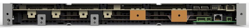
Table of Contents
    1. Introduction to CE+T...............................................................................................................................           6
    2. Abbreviations..........................................................................................................................................       7
    3. Warranty and Safety Conditions..............................................................................................................                  8
       3.1 Disclaimer....................................................................................................................................            8
       3.2 Technical care..............................................................................................................................              8
       3.3 Installation...................................................................................................................................           9
             3.3.1 Handling..........................................................................................................................                9
             3.3.2 Surge and transients.......................................................................................................                       9
             3.3.3 Other...............................................................................................................................              9
       3.4 Maintenance ...............................................................................................................................              10
       3.5 Replacement and Dismantling......................................................................................................                        10
    4. ECI Technology........................................................................................................................................       11
        4.1 On-line Mode...............................................................................................................................             12
        4.2 Safe Mode....................................................................................................................................           12
        4.3 EPC Mode....................................................................................................................................            12
        4.4 Mix Mode & Walk-in Mode............................................................................................................                     12
    5. Building Blocks.......................................................................................................................................       13
        5.1 Bravo 10 - 48/230 .......................................................................................................................               13
              5.1.1 Inverter...........................................................................................................................             13
              5.1.2 Sub-rack........................................................................................................................                15
        5.2 Controller Unit..............................................................................................................................           15
              5.2.1 Inview S..........................................................................................................................              15
              5.2.2 Inview S - Connections....................................................................................................                      15
              5.2.3 Inview Slot......................................................................................................................               16
        5.3 Manual By-Pass...........................................................................................................................               17
    6. A la Carte................................................................................................................................................   18
    7. Installation of Bravo 10 - Shelf................................................................................................................             19
        7.1 Mounting kit for Bravo 10 - shelf..................................................................................................                     19
        7.2 Electrical Installation for Bravo 10 - Shelf.....................................................................................                       20
               7.2.1 Pre requisites..................................................................................................................               20
               7.2.2 Terminations...................................................................................................................                20
               7.2.3 Cable Routing and Fixation..............................................................................................                       21
               7.2.4 Grounding.......................................................................................................................               21
               7.2.5 DC...................................................................................................................................          21
               7.2.6 AC Input..........................................................................................................................             22
               7.2.7 AC Output........................................................................................................................              22
               7.2.8 Inview S with Bravo 10 System - Connections.................................................................                                   23
               7.2.9 Signalling........................................................................................................................             23

                                                         2 - Bravo 10 - 48/230 - User manual - v1.3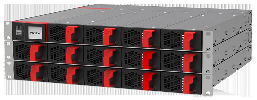
8.     Interface................................................................................................................................................   25
       8.1 Inverter module............................................................................................................................             25
       8.2 Inview S - LCD Display.................................................................................................................                 26
              8.2.1 LED indications...............................................................................................................                 26
              8.2.2 Menu structure................................................................................................................                 27
       8.3 Inview Slot - LCD Display.............................................................................................................                  27
              8.3.1 LED indications...............................................................................................................                 28
              8.3.2 Menu structure................................................................................................................                 28
       8.4 Inview S and Inview Slot - Web Interface......................................................................................                          28
              8.4.1 Login...............................................................................................................................           29
              8.4.2 Interface Areas................................................................................................................                29
9. Replacement procedures........................................................................................................................                  31
    9.1 Module - Bravo 10.......................................................................................................................                   31
         9.1.1 Removal..........................................................................................................................                   31
         9.1.2 Inserting..........................................................................................................................                 31
    9.2 Controller - Inview Slot.................................................................................................................                  32
         9.2.1 Removal..........................................................................................................................                   32
         9.2.2 Inserting..........................................................................................................................                 32
    9.3 Controller - Inview S.....................................................................................................................                 33
         9.3.1 Panel Mounting...............................................................................................................                       33
    9.4 Module Fan..................................................................................................................................               34
         9.4.1 Fan Removal...................................................................................................................                      34
         9.4.2 Fan Installation................................................................................................................                    35
10. Manual By-Pass (Optional)......................................................................................................................                36
    10.1 Pre-requisites...............................................................................................................................             36
    10.2 Manual By-Pass Operation...........................................................................................................                       36
         10.2.1 Normal to By-pass (Engage MBP)...................................................................................                                  36
         10.2.2 By-pass to Normal (Disengage MBP)...............................................................................                                   37
    10.3 MBP Auxiliary connection.............................................................................................................                     37
11. Finishing.................................................................................................................................................     38
12. Commissioning.......................................................................................................................................           39
     12.1 Check list.....................................................................................................................................          40
13. Trouble Shooting and Defective Situations Fixing.....................................................................................                          41
     13.1 Trouble Shooting..........................................................................................................................               41
     13.2 Defective modules.......................................................................................................................                 42
14. Maintenance...........................................................................................................................................         43
    14.1 Access Inview with Laptop...........................................................................................................                      43
    14.2 Manual check...............................................................................................................................               43
    14.3 Optional.......................................................................................................................................           43
    14.4 Manual By-Pass ..........................................................................................................................                 43

                                                     3 - Bravo 10 - 48/230 - User manual - v1.3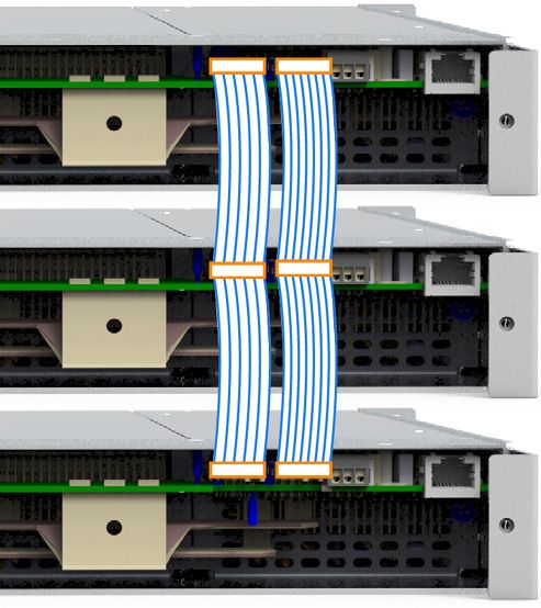
15. Service..................................................................................................................................................   44
16. Appendix................................................................................................................................................    45
     16.1 Bravo 10 - 48/230 - Dimensions..................................................................................................                      45
          16.1.1 Module............................................................................................................................             45
          16.1.2 Shelf...............................................................................................................................           45

                                                     4 - Bravo 10 - 48/230 - User manual - v1.3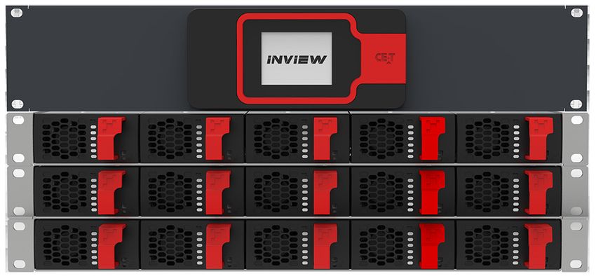
Release Note:

                      Release date
            Version                  Modified page number            Modifications
                      (DD/MM/YYYY)
                1.0     03/12/2018               -                   First release of the Manual
                1.1     19/08/2019               -                   Added Inview S Slot information
                1.2     25/11/2019      25 to 29, 34 & 35            Updated inview S and MBP section
                                                                     Updated mounting kit and fan replacement
                1.3     04/06/2021       18 and 33 - 34
                                                                     procedure

                                      5 - Bravo 10 - 48/230 - User manual - v1.3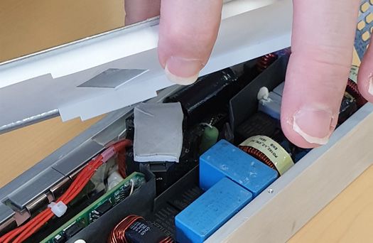
Introduction to CE+T

1. Introduction to CE+T
    CE+T Power designs, manufactures and markets a range of products for industrial operators with mission critical
    applications, who are not satisfied with existing AC backup systems performances, and related maintenance costs.
    Our product is an innovative AC backup solution that unlike most used UPS’s
      • Maximizes the operator’s applications uptime;
      • Operates with lowest OPEX;
      • Provides best protection to disturbances;
      • Optimizes footprint.
    Our systems are:
      • Modular
      • Truly redundant
      • Highly efficient
      • Maintenance free
      • Battery friendly
    CE+T power puts 60+ years expertise in power conversion together with worldwide presence to provide customized
    solutions and extended service 24/7 - 365 days per year.

                                       6 - Bravo 10 - 48/230 - User manual - v1.3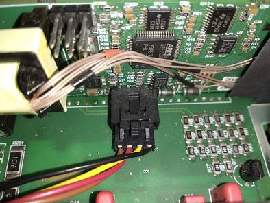
Abbreviations

2. Abbreviations
    AC 		       Alternating current
    DC 		       Direct current
    DHCP 		     Dynamic Host Configuration Protocol
    DSP 		      Digital Signal Processor
    ECI 		      Enhanced Conversion Innovation
    EPC 		      Enhanced Power Conversion
    ESD 		      Electro Static Discharge
    ETH 		      Ethernet
    HTTP 		     HyperText Transfer Protocol
    HTTPS 		    Secure HyperText Transfer Protocol
    LAN 		      Local Access Network
    MBB 		      Measure Box Battery
    MBP 		      Manual By-pass
    MET 		      Main Earth Terminal
    MIB 		      Management Information Base
    N 		        Neutral
    NTP 		      Network Time Protocol
    NUA		       Non-Urgent Alarm
    PCB 		      Printed Circuit Board
    PE 		       Protective Earth (also called Main Protective Conductor)
    PWR 		      Power
    REG 		      Regular
    SNMP 		     Simple Network Management Protocol
    TCP/IP 		   Transmission Control Protocol/Internet Protocol
    TRS 		      True Redundant Structure
    UA		        Urgent Alarm
    USB 		      Universal Serial Bus

                                   7 - Bravo 10 - 48/230 - User manual - v1.3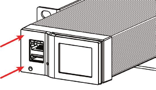
Warranty and Safety Conditions

3. Warranty and Safety Conditions*
           WARNING:
           The electronics in the power supply system are designed for an indoor, clean environment.
           When installed in a dusty and/or corrosive environment, outdoor or indoor, it is important to:
             • Install an appropriate filter on the enclosure door, or on the room’s air conditioning system.
             • Keep the enclosure door closed during operation.
             • Replace the filters on a regular basis.

           Important Safety Instructions and Save These Instructions.

3.1 Disclaimer
             • The manufacturer declines all responsibilities if equipment is not installed, used or operated according to the
               instructions herein by skilled technicians according to local regulations.
             • Warranty does not apply if the product is not installed, used and handled according to the instructions in the
               manuals.

3.2 Technical care
             • This electric equipment can only be repaired or maintained by a “qualified employee” with adequate training.
               Even personnel who are in charge of simple repairs or maintenance are required to have knowledge or
               experience related to electrical maintenance.
             • Please follow the procedures contained in this Manual, and note all the “DANGER”, “WARNING” AND “NOTICE”
               marks contained in this Manual. Warning labels must not be removed.
             • Qualified employees are trained to recognize and avoid any dangers that might be present when working on or
               near exposed electrical parts.
             • Qualified employees know how to lock out and tag out machines so the machines will not accidentally be turned
               on and injure employees working on them.
             • Qualified employees also know safety related work practices, including those by OSHA and NFPA, as well as
               knowing what personal protective equipment should be worn.
             • All operators are to be trained to perform the emergency shut-down procedure.
             • Never wear metallic objects such as rings, watches, or bracelets during installation, service and maintenance of
               the product.
             • Insulated tools must be used at all times when working with live systems.
             • When handling the system/units pay attention to sharp edges.
             • This product is suitable for use in a computer room.

* These instructions are valid for most CE+T Products/Systems. Some points might however not be valid for the product
described in this manual

                                                8 - Bravo 10 - 48/230 - User manual - v1.3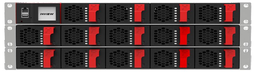
Warranty and Safety Conditions

3.3 Installation
          • This product is intended to be installed only in restricted access areas as defined by UL60950 and in accordance
            with the National Electric Code, ANSI/NFPA 70, or equivalent agencies.
          • The Inverter System may contain output over current protection in the form of circuit breakers. In addition to
            these circuit breakers, the user must observe the recommended UL listed upstream and downstream circuit
            breaker requirements as defined in this manual.
          • Please use extreme caution when accessing circuits that may be at hazardous voltages or energy levels.
          • The modular inverter rack is a dual input power supply. The complete system shall be wired in a way that both
            input and output leads can be de-energized when necessary.
          • REG systems and EPC systems that have no AC input wired and connected can be seen as independent power
            sources. To comply with local and international safety standards N (output) and PE shall be bonded. The bonded
            connection between N (output) and PE must be removed once the AC input is connected.
          • AC and DC circuits shall be terminated with no voltage / power applied (de-energized).
          • The safety standard IEC/EN62040-1-1 requires that, in the event of an output short circuit, the inverter must
            disconnect in 5 seconds maximum. The parameter can be adjusted on Inview; however, if the parameter is set at
            a value > 5 seconds, an external protection must be provided so that the short circuit protection operates within
            5 seconds. Default setting is 60 seconds.
          • The system is designed for installation within an IP20 or IP21 environment. When installed in a dusty or humid
            environment, appropriate measures (air filtering) must be taken.
          • All illustrations in the manual are for general reference, refer to the technical drawing which is received along
            with the system for exact information.

3.3.1 Handling
          • The cabinet shall not be lifted using lifting eyes.
          • Remove weight from the cabinet by unplugging the inverters. Mark inverters clearly with shelf and position for
            correct rebuild. This is especially important in dual or three phase configurations.

          • Empty inverter positions should not be left open. Replace either with module or dummy cover.

3.3.2 Surge and transients
        The mains (AC) supply of the modular inverter system shall be fitted with Lightning surge suppression and Transient
        voltage surge suppression suitable for the application at hand. Manufacturer’s recommendations of installation shall be
        adhered to. Selecting a device with an alarm relay for function failure is advised.
        Indoor sites are considered to have a working lightning surge suppression device in service.
          • Indoor sites Min Class II.
          • Outdoor sites Min Class I + Class II or combined Class I+II. The modular inverter system/rack can reach
            hazardous leakage currents. Earthing must be carried out prior to energizing the system. Earthing shall be made
            according to local regulations.

3.3.3 Other
          • Isolation test (Hi-Pot) must not be performed without instructions from the manufacturer.

                                            9 - Bravo 10 - 48/230 - User manual - v1.3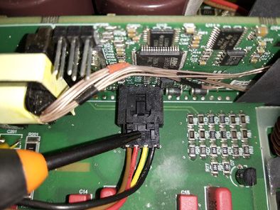
Warranty and Safety Conditions

3.4 Maintenance
         • The modular inverter system/rack can reach hazardous leakage currents. Earthing must be carried out prior to
           energizing the system. Earthing shall be made according to local regulations.
         • Prior to any work conducted on a system/unit make sure that AC input voltage and DC input voltage are
           disconnected.
         • Prior to accessing the system or modules, make sure all source of supply is disconnected.
           CAUTION – Risk of electric shock. Capacitors store hazardous energy. Do not remove cover until 5 minutes after
           disconnecting all sources of supply.
         • Some components and terminals carry high voltage during operation. Contact may result in fatal injury.

3.5 Replacement and Dismantling
         • ESD Strap must be worn when handling PCB’s and open units.
         • CE+T cannot be held responsible for disposal of the Inverter system and therefore the customer must segregate
           and dispose of the materials which are potentially harmful to the environment, in accordance with the local
           regulations in force in the country of installation.
         • If the equipment is dismantled, to dispose of its component products, you must comply with the local regulations
           in force in the country of destination and in any case avoid causing any kind of pollution.
       To download the latest documentation and software, please visit our website at
       www.cet-power.com

                                          10 - Bravo 10 - 48/230 - User manual - v1.3
ECI Technology
4. ECI Technology1
Inverter modules carrying the ECI logo and the EPC mark are triple port converters (AC in, DC in, AC out). Sinusoidal
output is converted from Mains or/and DC.
The block diagram below gives an explicit description of the topology and operation.
The module is built around the following sub-converters
• AC to DC at input
• DC to DC at input
• DC to AC at output
The energy can flow either from the AC source or the DC source under the control of the local DSP controller. Thanks to
internal energy buffering, the output sine wave is constant and disturbance free regardless of the active source.
The ECI works according to True Redundant Structure (TRS) that features decentralized and independent logic, redundant
communication bus and three internal levels of disconnection to isolate a module after internal failure.
This functionality is included in every inverter module. Running them in parallel provides a modular system with, no
single point of failure, always-conditioned output, high system efficiency and 0 ms source transfer time.
1 Information and data given in this chapter is intended to serve as an overview of the ECI Technology. Detailed features and parameters for each individual
module type in the range may differ and should be referred to in the dedicated data sheet.
11 - Bravo 10 - 48/230 - User manual - v1.3ECI Technology
4.1 On-line Mode
DC is the primary source of supply whilst Mains (AC) works as the secondary source. Switching time between DC input
and AC input is 0 ms (source transfer). The power delivered by the DC source (usually a battery, but possibly any other
type of DC generator) is converted to provide regulated and transient-free power to the load.
4.2 Safe Mode
Safe mode uses DC as the primary source of supply while Mains (AC) is on standby.
Mains (AC) is normally disconnected through an internal inlet relay and is only connected when down stream clearance
is required.
The transfer between DC and AC results in a typical transfer time of 10 ms.
Typically the safe mode is used in extremely harsh environments such as railways. Under such conditions, it provides
extra isolation against mains-borne disturbances.
4.3 EPC Mode
Mains input (AC) is the primary source whilst DC works as backup.
The ECI is designed to operate on Mains on a permanent basis and to deliver output voltage conditioned with low THD.
The output sine wave is physically independent of whether the source is AC (or) DC. If the Mains is out of tolerance
or goes down, the converter seamlessly switches to DC and the converter operates in “Back-up mode” (Changeover
switching time is 0 ms).
As soon as the Mains returns to its valid range, the EPC mode is automatically resumed.
The EPC mode offers higher efficiency (up to 96% depending on the model) without compromising the purity of the
output sine wave.
Remarks: REG modules:
Inverter modules carrying the ECI logo together with the REG mark work only with DC input. Sinusoidal output is converted
from DC with the module operating as a traditional inverter. EPC mode is not available with REG modules.
4.4 Mix Mode & Walk-in Mode
Under some circumstances the DC and AC sources can be combined. The sequence is defined by a user selectable set
of parameters. Start, control and exit are fully automatic.
A specific example of Mix-mode is the Walk-in mode where the transfer from DC source to AC source is ramped up
within a fixed and adjustable period of time.
12 - Bravo 10 - 48/230 - User manual - v1.3Building Blocks
5. Building Blocks
5.1 Bravo 10 - 48/230
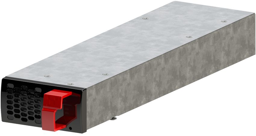
5.1.1 Inverter
Telecom / Datacom: Input 48 Vdc
230 Vac, 50/60 Hz
Output 230 Vac
Power 1250 VA / 1000 W
• The module is a triple port inverter.
• Hot-swappable and hot-pluggable.
• The module operator interface is LEDs showing converter status and output power.
• The module is equipped with a soft start.
• The fan in the module is equipped with alarm and run time meter, and it is field replaceable.
• 346 mm (D) x 87 mm (W) x 1U (H).
• 1.5 Kg.
5.1.1.1 Specifications
Model Bravo 10 - 48/230
General
Part Number: Module / Shelf T611730201 / T614730000
Cooling / Audible noise Fan forced cooling / < 65 dBA at one meter
MTBF 240 000 hrs (MIL-217IF)
Dielectric strength DC/AC 4300 Vdc
RoHS Compliant
Tested according ETS300-019-2-3 Class 3.1
Operating T° / Relative Humidity (RH) non-condensing -20°C to 65°C, power de-rating from 40°C to 65°C /
Max RH 95% for 96 hours per year
Tested according ETS300-019-2-1 Class 1.2
Storage T° / Relative Humidity (RH) non-condensing
-40°C to 70°C / Max RH 95% for 96 hours per year
Public transport T°/Relative Humidity (RH) non- Tested according ETS300-019-2-2 Class 3.1
condensing -40°C to 70°C / Max RH 95% for 96 hours per year
Material (casing) Zinc coated steel
AC Input Data
Nominal voltage (AC) 230 V
Voltage range (AC) 150 - 265 V
13 - Bravo 10 - 48/230 - User manual - v1.3Building Blocks
800 W @ 150 Vac / 1000 W @ >190 Vac linear
Brownout
decreasing
Power factor / THD > 99% / < 3%
Frequency range (selectable) / synchronization range 50 Hz (range 47 – 53 Hz) / 60 Hz (range 57 – 63 Hz)
DC Input Data
DC voltage: Nominal / range 48 VDC / (40-60V)*
Nominal current (at 48 Vdc and 1000 W output) 22.3 A
Maximum input current (at 48 Vdc for 15 second) /
34 A / < 10 mV RMS
voltage ripple
AC Output Data
Efficiency (Typical): Enhanced power conversion / on line 96% / >92.5%
Nominal voltage AC** Adjustable) 230 V (200 - 240 VAC)
Frequency / frequency accuracy 50 or 60 Hz / 0.03%
Nominal Output power 1250 VA / 1000 W
Short time overload capacity 150% (15 seconds)
Admissible load power factor Full power rating from 0 inductive to 0 capacitive
Total harmonic distortion (resistive load) < 3%
Load impact recovery time (10% - 90%) ≤ 0.4 ms
Nominal current 5.4 A @ 230 Vac
Crest factor at nominal power 3 : 1 for load P.F. ≤ 0.7
Short circuit clear up capacity 0 - 20 ms 22.7 A (peak) and 18.8 A (rms)
11.3 A (peak) and 9.5 A (rms) / 8.5 A (peak) and 7.1 A
Short circuit current after >20 ms -15 s / after 15 s
(rms)
AC output voltage stability ±1% from 10% to 100% load
In Transfer Performance
Max. voltage interruption / total transient voltage
0s/0s
duration (max)
Signalling & Supervision
Display Synoptic LED
Inview ranges / Inview S - T302004100, Inview Slot -
Supervision
T602004110, Inview GW - T602004000
Remote on / off On rear terminal of the shelf
Alarms output 2 dry contacts and 2 digital inputs
Safety & EMC
Safety EN62040-1
EN 61000-4-2 / EN 61000-4-3 / EN 61000-4-4 / EN
EMC 61000-4-5 / EN 61000-4-6 / EN 61000-4-8
ETSI EN 300386 v1.9.1
* Permanent 1000 W / derating apply based on internal heatsink T°.
** Operation within lower voltage networks leads to de-rating of power performances.
14 - Bravo 10 - 48/230 - User manual - v1.3Building Blocks
5.1.2 Sub-rack
• The shelf can be integrated in min 600 mm depth cabinets, Inch/ETSI mounting.
• The shelf house max four (4) modules and one (1) Inview Slot.
• The extension shelf house max five (5) modules.
• The shelf is designed with common DC input, AC Input and AC Output.
• Featured with rear protection cover (IP 20 ).
• Max 6.25 kVA / 5 kW per shelf.
• 370 mm (D) x 19” (W) x 1U (H).
• 2.5 Kg (without modules).
5.2 Controller Unit
5.2.1 Inview S
Inview S is an advanced monitoring and controller unit for Bravo 25, Bravo 10, Sierra 25, and Sierra 10 power systems.
It allows the user to easily access the system information through inbuilt powerful touch screen graphic display. In
addition to the touch screen display, the user can also access the system information through the web interface and
SNMP protocol.
The Inview S interface provides the user to access the configuration and setup files of the modules in the system. Also,
it is a controller for DC regulation.
Inview S can monitor up to 32 inverters/converters and featured with:
• LCD touch screen display
• 2 Digital Inputs
• 2 Output Relay contacts
• Records 5000 events as FIFO
5.2.2 Inview S - Connections
Inview S is composed of multiple network ports and inbuilt free potential contacts.
USB
- Digital Input 2
+
-
Digital Input 1
+
CE+T COM
C
NC Output Relay 2
ETH NO
C
CAN NC Output Relay 1
iso RS485 NO
-
PE Power 12 Vdc
+
15 - Bravo 10 - 48/230 - User manual - v1.3Building Blocks
• CE+T COM port is dedicated to establish connection between Inview S and Bravo 10 - shelf.
• ETH ( ) port is used for network connectivity and user can access the system information in the Web
Interface.
• CAN / iso RS485 port is used to establish communication between Inview S and MBB.
(Note: In future version, user can use this port for RS485-Modbus communication)
• USB port is used to access the Inview S configuration and setup files.
• Digital Inputs (D1 and D2): Two potential free Digital Inputs are available for customer connections.
Digital Input 1 is assigned for MBP operation if used.
Digital Input 2 is assigned for Surge Arrester if used.
• Output Relays (K1 and K2): Two output relays are available and can be used for Major and Minor Alarms.
• Power: The unregulated separate +12 V power supply is required for powering Inview S and this power should
not be shared with other devices. (CET can provide Auxiliary Power Supply converter and the part number is
T602004120).
5.2.3 Inview Slot
Inview Slot is an advanced monitoring and controller unit for Bravo
10 and Sierra 10 power systems. The product is specially designed
in 1U height to accommodate in the module shelf and reduces the
additional space in the cabinet.
It allows the user to easily access the system information through
inbuilt powerful LCD touch screen graphic display. In addition to the
touch screen display, the user can also access the system information
through the web interface.
The Inview Slot interface provides the user to access the configuration and setup files of the modules in the system.
Inview Slot can monitor up to 32 inverters/converters and featured with:
• LCD touch screen display
• 2 Digital Inputs
• 2 Output Relay contacts
• Records 5000 events as FIFO
Note: In the Bravo shelf, signalling connections are present at
left first slot. So the Inview Slot controller should be placed only
at the left side of the first slot in the shelf, while you are looking
from the front.
16 - Bravo 10 - 48/230 - User manual - v1.3Building Blocks
5.2.3.1 Inview Slot - Connections
Inview Slot has an ETH port and USB at the front. Output relays, free potential contacts, Modbus and power connections
are present at the rear side of the Inview Slot connected shelf.
Inview Slot - Front connections ETH
• LAN port is used for network connectivity and user can access the system
information in the Web Interface.
• USB port is used to access the Inview S configuration and setup files.
USB
Inview Slot - Shelf rear connections
• Digital Inputs (D1 and D2): Two potential free Digital Inputs are available for customer connections.
Digital Input 1 is assigned for MBP operation if used.
Digital Input 2 is assigned for Surge Arrester if used.
• Output Relays (K1 and K2): Two output relays are available and can be used for Major and Minor Alarms.
• CAN Modbus (RS485) port is used to establish communication between Inview Slot and MBB. It also provide the
+12 Vdc power to one connected MBB.
• Power: The additional +12 V for Inview Slot and it is from external Auxiliary power supply converter. This power
should not be shared with other devices.
By default, Inview Slot works on output DC from modules. If DC is not present, it takes +12 V from external Auxiliary
power supply converter (AC to DC).
Shelf Rear
CAN
Modbus PE
NO
NC
C
NO
NC
C
(RS485)
K1 K2 D1 D2 Power
5.3 Manual By-Pass
The manual by pass operates via manually operated switches to create a short circuit from the
AC main input directly to the output AC distribution. Standard manual by-pass is “Make before
Break”. When engaged or disengaged, no disturbance is transmitted to the load.
When MBP is engaged, inverter modules are switched off and can be removed without impacting
the load. The battery supply is not physically disconnected. After disconnecting the battery
supply (by opening the battery breakers), the shelf section is safe for maintenance.
Warning: When the system is in by-pass, the load is subjected to AC main disturbances. Before engaging manual
bypass, make sure the voltage difference between AC IN and AC OUT should be less than 5 Vac to limit the inrush
current.
17 - Bravo 10 - 48/230 - User manual - v1.3A la Carte
6. A la Carte
The A la Carte is pre-assembled and configured as a single phase or three phase system. The system comprises cabinet,
inverter sub rack, Bravo 10 inverter modules and controller.
Bravo 10 System with Inview S
Bravo 10 System with Inview Slot
• A la Carte is available in both EPC and REG mode.
• Dual input (AC and DC) inverter modules (EPC).
• 96% efficiency during normal operation (EPC).
• Always conditioned and filtered output voltage.
• Seamless transfer (0 ms) between primary and secondary source of supply.
• No single point of failure.
• Full modularity and redundancy.
Optional
• Manual by-pass
• Monitoring device
• AC output distribution.
18 - Bravo 10 - 48/230 - User manual - v1.3Installation of Bravo 10 - Shelf
7. Installation of Bravo 10 - Shelf
• Read safety instructions prior starting any work.
• Do NOT attempt to use lifting eyes to erect the cabinet.
• System is preferable handled without modules.
• Pay attention to the module position, make sure that modules are repositioned in the same slot.
• In three phase systems, the modules are configured as per phase 1, phase 2 and phase 3.
• As long as the system is not in operation, make sure that modules from one phase are not mixed with modules
from another phase. (When the system is running, modules can be moved from one phase to another without
issue.)
7.1 Mounting kit for Bravo 10 - shelf
Bravo 10 - shelf mounting kit is designed to fix in different depth cabinets. The part number is T319000001 and has
the following accessories in the kit.
4 x Fixing brackets 2 x Sliders 8 x (M5 Philips head screws and nuts)
2 x (M6 Hex socket screws, cage nuts and nuts) 6 x (M6 Philips head screws and cage nuts)
Perform the following steps to install the shelf mounting kit in the cabinet:
1. Adjust the slider and brackets depending upon the cabinet depth, and fix it with M5 screws and nuts. If holes are
available in the kit, fix it with the additional screws and nuts to increase the kit strength.
2. Place the assembled mounting kit in the cabinet and fix it on the front side at any one hole with the M6 Hex
socket screw and cage nut. (Note: Tighten the Hex socket screw with Allen key till it touches behind the metal
part.)
3. Fix the other end of the mounting kit at cabinet rear using the M6 Philips head screw and cage nut.
4. Similarly, assemble another mounting kit and fix it on another side of the cabinet.
Adjust the slider and brackets Fix it with screws and nuts Fix the assembled kit in the cabinet
Cage nut
Hex socket
screw
Mounting kit Cabinet frame
Screw, mounting kit & cage nut arrangement Tighten the screw till it touches the metal part
19 - Bravo 10 - 48/230 - User manual - v1.3Installation of Bravo 10 - Shelf
5. Place the shelf on the mounting kit and fix it with a M6 nut in the already installed hex socket screw used for the
mounting kit.
6. Fix the other hole of the shelf in the cabinet using M6 Philips head screw and cage nut.
7. Similarly, fix the other side of the shelf and insert modules in the corresponding slot.
Philips head screw Hex socket screw
Nut
Place the shelf in the cabinet and fix it Insert the modules in the shelf
7.2 Electrical Installation for Bravo 10 - Shelf
7.2.1 Pre requisites
• The sub-rack have markings for all terminations.
• All cables shall be rated at Min 90 deg C.
• Electrical terminations shall be tightened with 5 Nm.
• All connection screws are M5 x 12 mm.
• DC Input - Common (per shelf), check DC polarity.
• AC Input / AC output - Common (per shelf), check AC phase angle.
• Wire all positions in the sub-rack for future expansion.
• Input AC / Output AC / Input DC / Signal cables shall be separated.
• Cable crossings shall be done in 90 deg angles.
• Empty inverter positions shall be covered with dummy.
7.2.2 Terminations
Remote
(AC Out) (AC Out) (AC IN) (AC IN) ON/OFF
N L N L (To Parallel the 8 Pin To Inview S
(CE+T COM port)
Bravo 10 - shelves) 6 Pin
PE
Chassis Ground DC - DC +
GND GND Inview Slot
(AC Out) (AC IN) Terminals
Bravo 10 - 48/230 - Shelf Rear Details
20 - Bravo 10 - 48/230 - User manual - v1.3Installation of Bravo 10 - Shelf
7.2.3 Cable Routing and Fixation
Terminations are present at rear side of the shelf and it is protected with IP 20 metal cover.
Perform the following steps to connect power and signal cables:
1. Remove rear protection cover by unscrewing two screws.
2. Break the required knockouts and insert the grommets (1 x large, 2 x small, and 1-meter strip) for cable
protection, and it is shipped along with the shelf. (Warning: Take special attention while breaking knockouts to
avoid damaging the connectors, terminals and PCB in the shelf.)
AC IN and OUT cables entry – Right end of the shelf (1 - Knockout)
DC cables entry – Left end of the shelf (2 - Knockouts)
Knockouts are also available at top and bottom of the protection cover.
Note: Refer to section 16.1.2, page 45, to know more about knockout dimensions.
3. Connect the power and signal cables with supplied screws, refer section 7.2.2, page 20 for terminals
position.
4. Close the rear protection cover and tighten with two screws.
AC IN & OUT
AC O
ut
AC IN
Screw Screw DC -
DC + DC +
Signal
DC -
Remove two screws Remove protection cover Cable entries
7.2.4 Grounding
“PE Chassis Ground”
PE Chassis ground should be wired to MET (Main Earth Terminal) or distributed earth bar connected to MET, according
to local regulations.
7.2.5 DC
Model MCB per Shelf Cable, min Lug Torque
Insulated Ring
Bravo 10 - 48/230 160 A 50 mm2 5 Nm
type
Note: The Inner hole diameter of DC lug should be 6 mm (M6), and it is recommended to use only the supplied screws.
21 - Bravo 10 - 48/230 - User manual - v1.3Installation of Bravo 10 - Shelf
7.2.6 AC Input
WARNING !!!
Recommendation of IEC 60364 4. 43
431.3 Disconnection and reconnection of the neutral conductor in multi-phase systems
Where disconnection of the neutral conductor is required, disconnection and reconnection shall be such that the
neutral conductor shall not be disconnected before the line conductors and shall be reconnected at the same
time as or before the line conductors.
WARNING !!!
Input Neutral is required to operate the Local Circuit
Inverter, UPS TFO Breaker
L1
In TN-S System no 4 pole input switch or Inverter L2
circuit breaker shall be used. If you have to UPS L3
use 4 pole protective device, be aware that
N
the neutral against the ground is floating.
PE
The inverter, UPS will operate without
problem but you may infringe the local
regulation.
Model MCB per Shelf Cable, min Connector Lug Torque
Insulated Ring
Bravo 10 - 48/230 40 A 6 mm2 M6 5 Nm
type
Note: Icc value measured as 50 Arms per shelf with five modules.
7.2.7 AC Output
Model MCB per Shelf Cable, min Connector Lug Torque
Insulated Ring
Bravo 10 - 48/230 32 A 6 mm2 M6 5 Nm
type
22 - Bravo 10 - 48/230 - User manual - v1.3Installation of Bravo 10 - Shelf
7.2.8 Inview S with Bravo 10 System - Connections
1. Connect module shelf RJ45 port and Inview S CE+T COM port using RJ45 straight cable.
2. Connect Inview S CAN/iso RS485 port and Measure Box Battery CAN1 port using RJ45 straight cable.
2
CAN 1 CAN / iso RS485
RJ45 Cable
Measure Box Battery Inview S
CE+T COM
1 RJ45 Cable
RJ45
Module Shelf
7.2.9 Signalling
Each shelf comprise of 8 and 6 pin connector, Remote ON/OFF and ETH port for communication. The PCB at the bottom
of the rear shelf is for Inview Slot. It can only be accessed if Inview Slot connected to that shelf.
Remote
8 Pin To Inview S
ON/OFF
(CE+T COM port)
6 Pin 1 2 3
Inview Slot
Terminals
CAN
Modbus PE
NO
NC
C
NO
NC
C
(RS485)
K1 K2 D1 D2 Power
7.2.9.1 Remote ON/OFF
The shelf is by default equipped with a connection between pin 3 and 2. If remote ON/OFF is not used the strap shall
remain in all connected shelves. Should the remote ON/OFF be used, all straps must be removed and in one (1) shelf
replaced with a changeover contact or emergency button.
• The remote ON/OFF switch the output AC OFF.
• Input AC and input DC is not affected by the remote ON/OFF.
• The remote ON/OFF can be connected to any shelf.
23 - Bravo 10 - 48/230 - User manual - v1.3Installation of Bravo 10 - Shelf
• The remote ON/OFF requires changeover contacts, one input opens as the other close.
If both transitions are not picked up the status is not changed.
Relay characteristics (Remote ON/OFF)
• Signal voltage +5 VDC (galvanic insulated)
• Max wire size 1 mm2
Functional table for remote ON/OFF function
# Pin 1-3 Pin 2-3 Status Indication
1 Open Open Normal operation All (Green)
AC output (OFF)
2 Closed Open OFF AC Input (Green)
DC Input (Green)
3 Open Closed Normal operation All (Green)
4 Closed Closed Normal operation All (Green)
Warning! If remote ON/OFF is not used, pin 2 and 3 MUST be bridged together.
7.2.9.2 Internal bus (Bus 6 pin / Bus 8 pin) 6 Pin 8 Pin
Bus Cable Bus Cable
• In a la carte system, Internal bus is pre installed and connected in series from
the first shelf to last shelf.
• Internal bus is comprised of 6 and 8 pole CAN bus cables.
• If more than one shelf is ordered separately and installed in others cabinet, 6
and 8 pin connector of each shelf should be connected in series with all shelf
using CAN bus cables.
• The internal bus connectors are sensitive and special caution should be taken
during installation to keep them out of harms way.
24 - Bravo 10 - 48/230 - User manual - v1.3Interface
8. Interface
8.1 Inverter module
AC OUT
DC IN
AC IN
Output
Power
Status
Inverter Status LED Description Remedial action
OFF No input power or forced stop Check environment
Permanent green Operation
Converter OK but working conditions are
Blinking green
not fulfilled to operate properly
Blinking green/orange alternatively Recovery mode
Permanent orange Starting mode
Blinking orange Modules cannot start Check Inview
Blinking red Recoverable fault
Permanent red Non recoverable fault Send module back for repair
Output Power (redundancy not counted)
5% to 40 to 80 to 100% =Interface
8.2 Inview S - LCD Display
Inview S LCD interface is a 2.8-inch touch screen. It does not have any have any user account, the user can only view
the system details. The LCD interface is protected with the PIN during any action request.
Once system is powered upon, the Inview S is up and ready for operation.
[1]
[2]
[3]
• [1] Header
Displays the title of the current page and navigation buttons for next and previous page. In some pages, Up and
Down navigation buttons appear at the right side, indicating more contents are present.
• [2] Information Area
Provides information about the corresponding page.
• [3] Toolbar
The toolbar is present at the bottom throughout the interface, to provide quick access to following pages:
Measures
Settings
Alarms and Logs
8.2.1 LED indications
Three LED’s are present at front side of the controller to indicate major alarm, minor alarm, and system status
Major Alarm
Minor Alarm
System Status
26 - Bravo 10 - 48/230 - User manual - v1.3Interface
8.2.2 Menu structure
The home page is the default page in the LCD, and other pages display as below sequence in a circular list.
Inview S
LCD Interface
Monitoring Settings Events
Refresh Cutoff
Information Logs
Module list Alarms
Home AC Out DC AC In System
8.3 Inview Slot - LCD Display
Once the system is powered upon, the Inview Slot is up and ready for operation. The LCD is a 1.8-inch touch screen and
user can only view the system details through the interface.
[1]
Navigation
arrow
[2]
• [1] Interface area
Interface area provides information about the corresponding page. At the bottom of the screen, left and right
arrows are present for moving next and the previous screen. In some screens, up and down arrows appear at the
top of the page, indicating more contents are present
• [2] Status bar
The status bar appears throughout the interface and illuminate the current page icon.
27 - Bravo 10 - 48/230 - User manual - v1.3Interface
8.3.1 LED indications
Three LED’s are present behind the front black plastic of the controller to indicate major alarm, minor alarm, and system
status. These LED’s are not visible until they illuminate during the corresponding action occurs.
Front black plastic
(Red) Major alarm
(Orange) Minor alarm
(Green) System status
8.3.2 Menu structure
The home page is the default page in the LCD interface, and other pages are arranged in the below sequence.
Inview Slot
LCD Interface
Info Action Logs Events Home AC In AC Out DC System
8.4 Inview S and Inview Slot - Web Interface
The web interface of both controller Inview S and Inview Slot is same, and the user can access the controller on the
laptop through ETH port.
This section provides an overview of the web interface, refer Inview S user manual for detailed information.
28 - Bravo 10 - 48/230 - User manual - v1.3Interface
8.4.1 Login
Open the web browser and type the default IP address 10.250.250.1 in
the address field and press enter.
Note: Use any one of the following latest version of web browser:
Google Chrome, Mozilla Firefox, Safari or Microsoft edge.
Inview S has three login – Basic, Expert and Admin. All three login is
password protected.
The default password for all three logins is “1234”.
Basic login can only browse the pages and download the files, but Expert
and Admin login can access and also modify the system parameter
values.
An auto-logout feature is available to avoid a user being connected all the time. When no action is performed for more
than 10 minutes, the session will expire and goes to login screen.
8.4.2 Interface Areas
1 Header
2 Main Page
1
2
8.4.2.1 Header
1 2 3 4 5 6 7
The tabs in header provide quick access to the corresponding pages.
1 Home: Clicking on goes to the home page from any page you are accessing in the interface.
2 Breadcrumbs: Provide navigation of the page. It trails all levels so that user can know where you are within the
interface and can go to any previous menu.
3 Display the date, time and the site name of the system.
29 - Bravo 10 - 48/230 - User manual - v1.3Interface
4 Events: Clicking on goes to Events and Logs page.
5 Settings: Clicking on provide access to Users, Parameters and Maintenance pages.
6 Info: Clicking on in the home page, provides brief information about the system, while in other pages provide
the latest three ongoing events.
7 Account: Provides the information of which account is logged in (Basic, Expert or Admin). Clicking on drop-down
arrow user can access the following pages:
Administration - Provide quick access to Users, Parameters and Maintenance pages.
(Administration page will appear only in Expert login).
About - Provides the information of Inview product details and network connectivity details.
Logout - An act of logging out of an Inview S.
8.4.2.2 Home Page
5
1 3 4
2
1 AC Input: Clicking on the AC Input region displays the page contain all measurements regarding AC Input.
2 DC: Clicking on the DC region displays the page contain all measurements regarding Battery and DC Output.
3 Power System: Clicking on the Power System region display the page contain regarding system information
such as overall system power and also in each phase, configured modules, active modules, and list of detected
modules and accessories.
4 AC Output: Clicking on the AC Output region displays the page contain all measurements regarding AC Output.
Regardless of the system configuration (1P, 3P), display the power fed to the load on each phase.
5 Notifications: Display the current generated alarms and events.
Note: To know more about Inview S and Inview Slot operation, refer to the Inview manual and it is available on request.
30 - Bravo 10 - 48/230 - User manual - v1.3Replacement procedures
9. Replacement procedures
9.1 Module - Bravo 10
• The Bravo inverter is hot swappable.
• When a new module is inserted in a live system it automatically adapts to a working set of parameters.
• When a new module is inserted in a live system it automatically assigns the next available address.
9.1.1 Removal
Notice: When one or several inverter modules is/are removed access to live parts becomes possible. Replace module(s)
with dummy cover without delay.
1. Insert a soft edged pin into the hole to unlock the latch. (Hole diameter is 3 mm)
2. Push the pin and simultaneously pull the module using front handle.
3. Remove the module from shelf and replace with a new module or dummy cover.
Pin
Hole
Insert the pin into the hole Push the pin and pull the module Remove the module from shelf
9.1.2 Inserting
1. Check module compatibility (DC Voltage!).
2. Place the module and slide into the shelf.
3. Push the module firmly using the front handle, until the module rear is connected correctly with shelf.
4. Make sure the bottom latch in the module is locked in the shelf.
5. The module will start up and take the first address available on the bus.
Place the module & slide into the shelf Push firmly until module is engaged Make sure the latch is locked in the shelf
31 - Bravo 10 - 48/230 - User manual - v1.3Replacement procedures
9.2 Controller - Inview Slot
9.2.1 Removal
1. Insert a soft edged pin into the hole to unlock the latch. (Hole diameter is 3 mm)
2. Gently push and press down the pin to unlock the latch and then remove the controller.
Warning: while removing the controller from the shelf, hold the top and bottom part of front plastic. Do not press on the
touch screen.
3. Remove the controller from shelf and replace with a new unit or dummy cover.
Pin
Hole
Insert the pin into the hole Push and press down the pin, and pull the unit Remove the module from shelf
9.2.2 Inserting
1. Place the Inview Slot and slide into the shelf.
2. Push the unit firmly until the controller rear part is engaged correctly with shelf.
Warning: while inserting the controller into the shelf, push on the left side (ETH and USB port) of the controller. Do not
press on the touch screen.
3. Make sure the latch is locked in the shelf.
4. The controller begins to start up and read the parameters from modules in the live system.
Place the module & slide into the shelf Push firmly until unit is engaged Make sure the latch is locked in the shelf
32 - Bravo 10 - 48/230 - User manual - v1.3Replacement procedures
9.3 Controller - Inview S
9.3.1 Panel Mounting
Before mounting the Inview S in the system, route all the required connection cables from the system and place near to
the Inview S mounting location.
1. Place the Inview S in the panel sheet.
2. Lock all the four latches at the rear side of the Inview S in the panel sheet.
3. Connect required connection cables to the Inview S.
4. Place the panel sheet in the system and fix it with screws
Latch
Place the Inview S in the panel sheet Fix it with four latches
Connect wires and place the panel sheet in the cabinet Fix the panel sheet with screws
Dimensions
are in mm
Panel sheet - cut-out details
33 - Bravo 10 - 48/230 - User manual - v1.3Replacement procedures
9.4 Module Fan
The module’s fan is speed control, and its speed varies depending upon the load percentage and module internal
temperature. Its life is approximately 60,000 (Sixty Thousand) hours. The module has fan runtime meters and fans failure
alarms, and the fan failure can result from a failing fan or driver circuit.
9.4.1 Fan Removal
1. Remove the module from the shelf and place it on the flat surface.
Caution: Prior to accessing the module, wait at least 5 minutes to allow internal capacitors to discharge.
Note: To remove the fan from the module, we need to remove the module front cover and bottom sheet.
2. To unlock the front cover, remove the screw at top of the module using Philips head screwdriver. But do not
remove the cover.
3. Place the module upside down and remove the bottom sheet by removing 10 screws using a T6 screw driver.
(8 screws at bottom sheet and 2 at rear). Note: Pay attention to the thermal pad, which stays on the transformer.
Thermal pad
Remove the screw at Remove the 10 screws at
Pay attention to the thermal pad on the transformer
top of the module bottom sheet and rear
4. Remove the front cover with the fan by pulling horizontally (Note the fan position on the front cover).
5. Press firmly on the fan connector using a screwdriver, unlock it, and remove it from the board.
(Note the fan connector position and wire routing).
Remove the front cover Press firmly and remove the
with Fan Fan Connector
34 - Bravo 10 - 48/230 - User manual - v1.3Replacement procedures
9.4.2 Fan Installation
1. Replace with the new fan in the front cover, and connect the fan connector to the board (Ensure the fan
connector is placed correctly and followed the wire routing as it was before).
2. Place the front cover with the fan and fix the screw at the top of the module using a star screwdriver.
Replace the new fan and Place the front cover with Fan Fix the screw at
Fix the connector top of the module
3. Make sure the thermal pad is placed correctly on the transformer.
4. Place the bottom sheet and pay attention to the Formex pass between the extruded housing and the components
(especially Blue and Brown capacitors). Make sure it is easily supported on the extruded housing, and there is no
bulging or warping.
5. Fix the bottom sheet by 10 screws using a T6 screw driver.
Place the bottom sheet and Fix the 10 screws at
No bulging and warping
pay attention to the Formex bottom sheet and rear
6. Place the module in corresponding slot and check the fan operation.
7. After replacing the new fan, reset the fan alarm. To do this, go to the corresponding module page on the web
interface and click the “SET NEW FAN INSTALLED” button.
• Module page in Inview SW 3.0: go to Home page > Power system and click the respective module from the list.
• Module page in Inview SW 5.0: go to Dashboard > Power system and click the respective module from the list.
35 - Bravo 10 - 48/230 - User manual - v1.3You can also read