LCA PRE, LC EXC Manual - LED Driver - Tridonic
←
→
Page content transcription
If your browser does not render page correctly, please read the page content below
LED Driver

LCA PRE, LC EXC
Manual
Manual LCA PRE / LC EXC | 03-2020 | 2.9 | en

Table of contents

1. Validity 4
  1.1. Copyright . . . . . . . . . . . . . . . . . . . . . . . . . . . . . . . . . . . . . . . . . . . . . . . . . . . . . . . . . . . . . . . . . . . . . . . . . . . . . . . . . . . . . . . . . . . . . . . . . . . . . . . . . . . . . . . . . 4
  1.2. Imprint . . . . . . . . . . . . . . . . . . . . . . . . . . . . . . . . . . . . . . . . . . . . . . . . . . . . . . . . . . . . . . . . . . . . . . . . . . . . . . . . . . . . . . . . . . . . . . . . . . . . . . . . . . . . . . . . . . . 4

2. General safety instructions 5
  2.1. Intended use . . . . . . . . . . . . . . . . . . . . . . . . . . . . . . . . . . . . . . . . . . . . . . . . . . . . . . . . . . . . . . . . . . . . . . . . . . . . . . . . . . . . . . . . . . . . . . . . . . . . . . . . . . . . . . 5
  2.2. Dangers associated with the operation of the system . . . . . . . . . . . . . . . . . . . . . . . . . . . . . . . . . . . . . . . . . . . . . . . . . . . . . . . . . . . . . . . . . . . . . . . 5
  2.3. Environment . . . . . . . . . . . . . . . . . . . . . . . . . . . . . . . . . . . . . . . . . . . . . . . . . . . . . . . . . . . . . . . . . . . . . . . . . . . . . . . . . . . . . . . . . . . . . . . . . . . . . . . . . . . . . 5
  2.4. Additional instructions . . . . . . . . . . . . . . . . . . . . . . . . . . . . . . . . . . . . . . . . . . . . . . . . . . . . . . . . . . . . . . . . . . . . . . . . . . . . . . . . . . . . . . . . . . . . . . . . . . . . 6

3. Description and key features 7
  3.1. Description of key features . . . . . . . . . . . . . . . . . . . . . . . . . . . . . . . . . . . . . . . . . . . . . . . . . . . . . . . . . . . . . . . . . . . . . . . . . . . . . . . . . . . . . . . . . . . . . . . . 7
  3.2. Two-part layer structure . . . . . . . . . . . . . . . . . . . . . . . . . . . . . . . . . . . . . . . . . . . . . . . . . . . . . . . . . . . . . . . . . . . . . . . . . . . . . . . . . . . . . . . . . . . . . . . . . . 8
  3.3. Housing variants . . . . . . . . . . . . . . . . . . . . . . . . . . . . . . . . . . . . . . . . . . . . . . . . . . . . . . . . . . . . . . . . . . . . . . . . . . . . . . . . . . . . . . . . . . . . . . . . . . . . . . . . 10
  3.4. Adjustable output current, voltage and power . . . . . . . . . . . . . . . . . . . . . . . . . . . . . . . . . . . . . . . . . . . . . . . . . . . . . . . . . . . . . . . . . . . . . . . . . . . . . 11
  3.5. Operating Window Multichannel . . . . . . . . . . . . . . . . . . . . . . . . . . . . . . . . . . . . . . . . . . . . . . . . . . . . . . . . . . . . . . . . . . . . . . . . . . . . . . . . . . . . . . . . . . 14

4. Compatibility between LED module and LED Driver 23
  4.1. Comparison of data sheet values with a 4-point guideline . . . . . . . . . . . . . . . . . . . . . . . . . . . . . . . . . . . . . . . . . . . . . . . . . . . . . . . . . . . . . . . . . 23
  4.2. Application of the 4-point guideline . . . . . . . . . . . . . . . . . . . . . . . . . . . . . . . . . . . . . . . . . . . . . . . . . . . . . . . . . . . . . . . . . . . . . . . . . . . . . . . . . . . . . . 25
  4.3. Practical tests . . . . . . . . . . . . . . . . . . . . . . . . . . . . . . . . . . . . . . . . . . . . . . . . . . . . . . . . . . . . . . . . . . . . . . . . . . . . . . . . . . . . . . . . . . . . . . . . . . . . . . . . . . . 31

5. Installation notes 32
  5.1. Safety information . . . . . . . . . . . . . . . . . . . . . . . . . . . . . . . . . . . . . . . . . . . . . . . . . . . . . . . . . . . . . . . . . . . . . . . . . . . . . . . . . . . . . . . . . . . . . . . . . . . . . . . 32
  5.2. Function of the earth terminal . . . . . . . . . . . . . . . . . . . . . . . . . . . . . . . . . . . . . . . . . . . . . . . . . . . . . . . . . . . . . . . . . . . . . . . . . . . . . . . . . . . . . . . . . . . . 33
  5.3. Routing the wires . . . . . . . . . . . . . . . . . . . . . . . . . . . . . . . . . . . . . . . . . . . . . . . . . . . . . . . . . . . . . . . . . . . . . . . . . . . . . . . . . . . . . . . . . . . . . . . . . . . . . . . . 35
  5.4. External fuse for DC operation . . . . . . . . . . . . . . . . . . . . . . . . . . . . . . . . . . . . . . . . . . . . . . . . . . . . . . . . . . . . . . . . . . . . . . . . . . . . . . . . . . . . . . . . . . . 36
  5.5. Maximum loading of circuit breakers . . . . . . . . . . . . . . . . . . . . . . . . . . . . . . . . . . . . . . . . . . . . . . . . . . . . . . . . . . . . . . . . . . . . . . . . . . . . . . . . . . . . . 37

6. Functions 41
  6.1. corridorFUNCTION V2 (PRE only) . . . . . . . . . . . . . . . . . . . . . . . . . . . . . . . . . . . . . . . . . . . . . . . . . . . . . . . . . . . . . . . . . . . . . . . . . . . . . . . . . . . . . . . . 41
  6.2. DSI (PRE only) . . . . . . . . . . . . . . . . . . . . . . . . . . . . . . . . . . . . . . . . . . . . . . . . . . . . . . . . . . . . . . . . . . . . . . . . . . . . . . . . . . . . . . . . . . . . . . . . . . . . . . . . . . 46
  6.3. switchDIM (PRE only) . . . . . . . . . . . . . . . . . . . . . . . . . . . . . . . . . . . . . . . . . . . . . . . . . . . . . . . . . . . . . . . . . . . . . . . . . . . . . . . . . . . . . . . . . . . . . . . . . . . 47
  6.4. Power-up Fading (PRE only) . . . . . . . . . . . . . . . . . . . . . . . . . . . . . . . . . . . . . . . . . . . . . . . . . . . . . . . . . . . . . . . . . . . . . . . . . . . . . . . . . . . . . . . . . . . . . 51
  6.5. DALI (PRE only) . . . . . . . . . . . . . . . . . . . . . . . . . . . . . . . . . . . . . . . . . . . . . . . . . . . . . . . . . . . . . . . . . . . . . . . . . . . . . . . . . . . . . . . . . . . . . . . . . . . . . . . . . 52
  6.6. ready2mains . . . . . . . . . . . . . . . . . . . . . . . . . . . . . . . . . . . . . . . . . . . . . . . . . . . . . . . . . . . . . . . . . . . . . . . . . . . . . . . . . . . . . . . . . . . . . . . . . . . . . . . . . . . . 54
  6.7. Constant Light Output (PRE only) . . . . . . . . . . . . . . . . . . . . . . . . . . . . . . . . . . . . . . . . . . . . . . . . . . . . . . . . . . . . . . . . . . . . . . . . . . . . . . . . . . . . . . . . 55
  6.8. DC recognition . . . . . . . . . . . . . . . . . . . . . . . . . . . . . . . . . . . . . . . . . . . . . . . . . . . . . . . . . . . . . . . . . . . . . . . . . . . . . . . . . . . . . . . . . . . . . . . . . . . . . . . . . . 57
  6.9. Dimming on DC (PRE only) . . . . . . . . . . . . . . . . . . . . . . . . . . . . . . . . . . . . . . . . . . . . . . . . . . . . . . . . . . . . . . . . . . . . . . . . . . . . . . . . . . . . . . . . . . . . . . 58
  6.10. Intelligent Temperature Guard . . . . . . . . . . . . . . . . . . . . . . . . . . . . . . . . . . . . . . . . . . . . . . . . . . . . . . . . . . . . . . . . . . . . . . . . . . . . . . . . . . . . . . . . . . 59
  6.11. colourSWITCH . . . . . . . . . . . . . . . . . . . . . . . . . . . . . . . . . . . . . . . . . . . . . . . . . . . . . . . . . . . . . . . . . . . . . . . . . . . . . . . . . . . . . . . . . . . . . . . . . . . . . . . . . . 62

c                                                                                                                                                                                                                                    2 / 72

Manual LCA PRE / LC EXC | 03-2020 | 2.9 | en

Table of contents

      6.12. proportionSWITCH (PRE only) . . . . . . . . . . . . . . . . . . . . . . . . . . . . . . . . . . . . . . . . . . . . . . . . . . . . . . . . . . . . . . . . . . . . . . . . . . . . . . . . . . . . . . . . . . 66
      6.13. 1-10 V Interface . . . . . . . . . . . . . . . . . . . . . . . . . . . . . . . . . . . . . . . . . . . . . . . . . . . . . . . . . . . . . . . . . . . . . . . . . . . . . . . . . . . . . . . . . . . . . . . . . . . . . . . . . 71

7. Reference list 72
      7.1. Additional information . . . . . . . . . . . . . . . . . . . . . . . . . . . . . . . . . . . . . . . . . . . . . . . . . . . . . . . . . . . . . . . . . . . . . . . . . . . . . . . . . . . . . . . . . . . . . . . . . . . 72
      7.2. Downloads . . . . . . . . . . . . . . . . . . . . . . . . . . . . . . . . . . . . . . . . . . . . . . . . . . . . . . . . . . . . . . . . . . . . . . . . . . . . . . . . . . . . . . . . . . . . . . . . . . . . . . . . . . . . . . 72
      7.3. Technical data . . . . . . . . . . . . . . . . . . . . . . . . . . . . . . . . . . . . . . . . . . . . . . . . . . . . . . . . . . . . . . . . . . . . . . . . . . . . . . . . . . . . . . . . . . . . . . . . . . . . . . . . . . . 72

...

c                                                                                                                                                                                                                                 3 / 72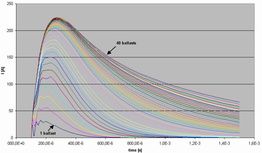
Manual LCA PRE / LC EXC | 03-2020 | 2.9 | en

Scope of documentation

These operating instructions are valid for LED Driver of the LCA PRE and LC EXC series. Not included are LC EXC Driver with wide
voltage input range und LC OTD Driver.
If a reference is made to one of the two versions then the descriptions are valid only for that version.

The series comprises additional versions. However, the other versions ADV, SNC, ECO, TOP, TEC are not covered in detail within this
documentation.

TRIDONIC GmbH & Co KG is constantly striving to develop all its products. This means that there may be changes in form, equipment
and technology.
Claims cannot therefore be made on the basis of information, diagrams or descriptions in these instructions.
The latest version of these operating instructions is available on our home page at
http://www.tridonic.com/com/en/operating-instructions.asp

1.1. Copyright
This documentation may not be changed, expanded, copied or passed to third parties without the prior written agreement of
TRIDONIC GmbH & Co KG.
We are always open to comments, corrections and requests. Please send them to info@tridonic.com

1.2. Imprint
Tridonic GmbH & Co KG
Färbergasse 15
6851 Dornbirn
Austria

T +43 5572 395-0
F +43 5572 20176

www.tridonic.com

...

c                                                                                                                           4 / 72
Manual LCA PRE / LC EXC | 03-2020 | 2.9 | en

General safety instructions

The instructions in this section have been compiled to ensure that operators and users of LED Driver LCA PRE and LC EXC from
Tridonic are able to detect potential risks in good time and take the necessary preventative measures.
The operator must ensure that all users fully understand these instructions and adhere to them. This device may only be installed and
configured by suitably qualified personnel.

2.1. Intended use
2.1.1. Proper use
Operation of LED light modules. The device may only be used for this intended purpose.

2.1.2. Improper use
Outdoor use. Extensions and modifications to the product.

 ½ WARNING!
 Improper use could result in injury, malfunction or damage to property.
 It must be ensured that the operator informs every user of existing hazards.

2.2. Dangers associated with the operation of the system
 ½ DANGER!
 Danger of electrocution
 Disconnect the power to the entire lighting system before working on the lighting system!

2.3. Environment
 ½ DANGER!
 Not to be used in corrosive or explosive environments.

 ½ CAUTION!
 Risk of damage caused by humidity and condensation

  _ Only use the control device in dry rooms and protect it against humidity!
  _ Prior to commissioning the system, wait until the control device is at room temperature and completely dry!

c                                                                                                                           5 / 72
Manual LCA PRE / LC EXC | 03-2020 | 2.9 | en

General safety instructions

2.4. Additional instructions
 ½ CAUTION!
      Electromagnetic compatibility (EMC)
      Although the device meets the stringent requirements of the appropriate directives and standards on electromagnetic
      compatibility, it could potentially interfere with other devices under certain circumstances!

...

c                                                                                                                           6 / 72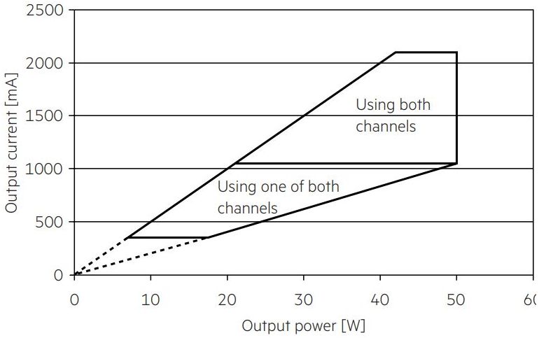
Manual LCA PRE / LC EXC | 03-2020 | 2.9 | en

Description and key features

12345, p.

3.1. Description of key features
LCA PRE and LC EXC is a portfolio of LED Drivers. It has been optimised and simplified to meet the typical requirements of LED
solutions.

      _ Different requirements:
        The layers PRE and EXC offer solutions for different requirements (e.g. dimming/fixed output, lifetime, applications)
      _ State-of-the-art dimming technology:
        Stepless dimming from 100 to 1 % (PRE) (see Two-part layer structure, p. 8).
      _ Broad range of casing shapes:
        Different casing shapes (compact, stretched compact, independent, low profile) and sizes for different built-in versions
      _ Adjustable output current:
        Simple option for setting current and voltage values transition-free (PRE and EXC) allows the device to be used with virtually
        all light modules
      _ Diversity of functions:
        Familiar and new functions, e.g. DALI, DSI, switchDIM, corridorFUNCTION, dimming (PRE only), ready2mains (PRE and EXC)
      _ Tunable White (PRE only):
        DT8: Dimming range: 3 - 100 %, colour temperature: 2,700 - 6,500 K, colourSWITCH
        2xCH / 4xCH DT 6: Dimming range: 1 - 100 %, proportionSWITCH

...

c                                                                                                                                  7 / 72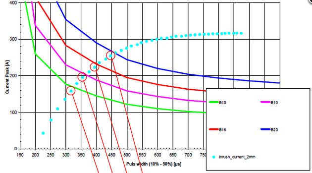
Manual LCA PRE / LC EXC | 03-2020 | 2.9 | en

Description of key features

3.2. Two-part layer structure
The layers LCA PRE and LC EXC differ as follows:

3.2.1. Dimming (PRE only)
 Portfolio                   PRE

 Dimmable

 Dimming method              Amplitude dimming

 Dimming range               100 to 1 %
                             100 to 3 % at TW DT8

 Dimming curve               Logarithmic dimming curve (standard)
                             Switching to linear dimming curve via masterCONFIGURATOR is possible.

 Dimming interface           DALI-2 DT6, DSI, ready2mains, corridorFUNCTION V2, switchDIM

 ready2mains
                             I NOTICE
                                 ready2mains is not available for TW DT8 and 2xCH / 4xCH DT 6 driver.

3.2.2. Functions
 Portfolio                                              PRE                                    EXC

 Constant Light Output

 Intelligent Temperature Guard

 Power-up Fading

 DC Operation                                           DC level adjustable                    DC level fixed
                                                        supporting EN 50172                    supporting EN 50172

 Constant Light Output

c                                                                                                                    8 / 72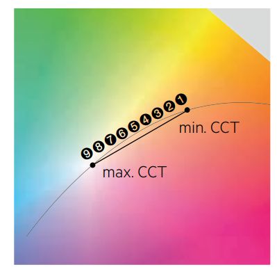
Manual LCA PRE / LC EXC | 03-2020 | 2.9 | en

Description of key features

3.2.3. Output current
      Portfolio           PRE                                                       EXC

      Adjustable
      output current

      Adjustable via...   DALI-2 DT6, ready2mains, I-select 2 plug (resistor)       ready2mains, I-select 2 plug (resistor)

      Step size           1 mA                                                      1 mA

      Tolerance           Further information can be found in the data sheet (see   Further information can be found in the data sheet (see
                          Reference list, p. 72).                                   Reference list, p. 72).

 I NOTICE
      ready2mains is not included in TW DT8 and 2xCH / 4xCH DT 6.

 I NOTICE
      Tunable White has device type DALI DT 8

 I NOTICE
      By using I-Select Plugs, all channels on the TW DT8 and 2xCH / 4xCH DT 6 will be set to the same current.

3.2.4. Technical data
      Portfolio                                                       PRE                                 EXC

      Rated supply voltage                                            220-240 V                           220-240 V

      Standby losses                                                  < 0.2 W

...

c                                                                                                                                  9 / 72
Manual LCA PRE / LC EXC | 03-2020 | 2.9 | en
Description of key features
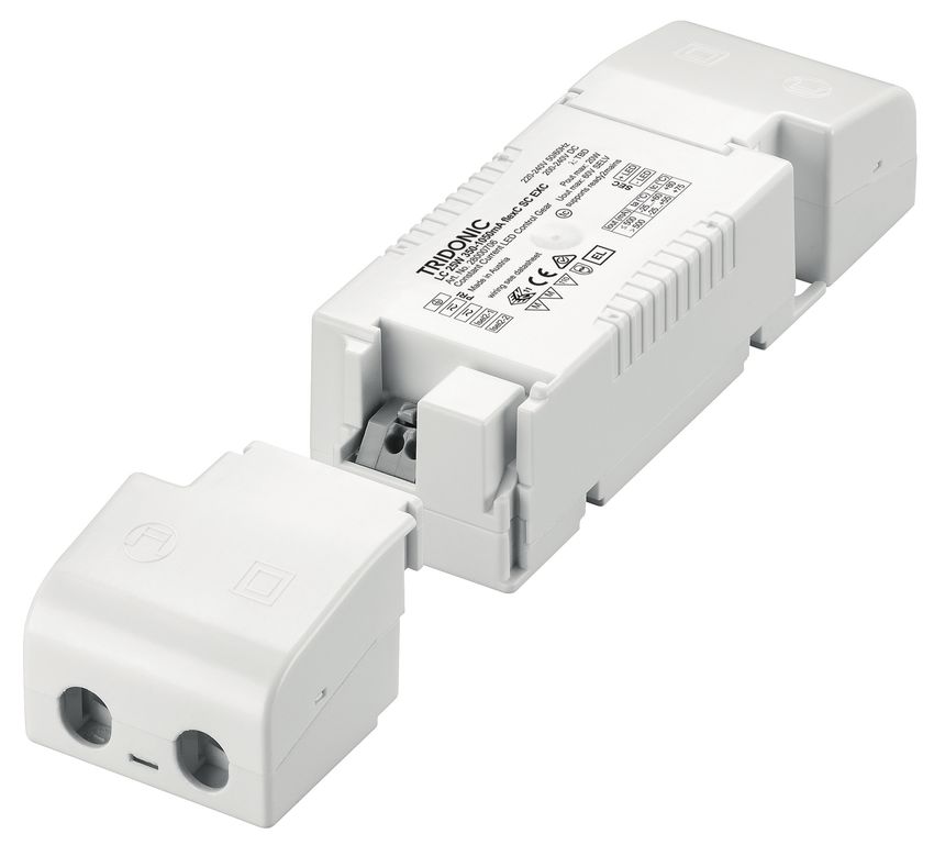
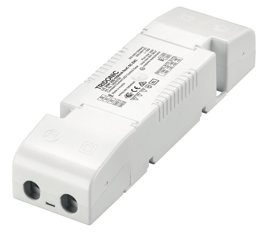
3.3. Housing variants
All the layers are available in three different housing variants: compact, independent and low profile.
Image Description
Housing variant compact
_ Compact shape for installation inside the luminaire casing (in-built)
_ Typical area of application: Spotlights, downlights
Housing variant stretched compact
_ Shape that can be used as compact or independent (for an installation outside the
luminaire strain relief can be attached to the casing)
_ Typical area of application: Spotlight, downlight
Housing variant independent
_ Long and small shape for installation outside the luminaire casing (remote)
_ Typical area of application: Spotlights, Downlights
_ Special characteristic: Full loop-through capability of mains and interface (DALI)
cables
Housing variant low profile
_ Flat shape for a space-saving installation inside the luminaire casing (in-built)
_ Typical area of application: area lighting, linear lighting
c 10 / 72Manual LCA PRE / LC EXC | 03-2020 | 2.9 | en Description of key features 3.4. Adjustable output current, voltage and power LCA PRE and LC EXC allow for different combinations of power and current based on the standard lumen packages available on the market. 3.4.1. Adjusting the Output current Layer Output current adjustable via... PRE DALI / masterCONFIGURATOR, ready2mains, I-select 2 plug, resistor EXC ready2mains, I-select 2 plug, resistor TW DT8 DALI / masterCONFIGURATOR, I-select 2 Plug, resistor 2xCH / 4xCH DT 6 DALI / masterCONFIGURATOR, I-select 2 Plug, resistor Adjusting the output current via DALI or ready2mains Further information about DALI (see DALI, p. 52) or ready2mains (see ready2mains, p. ) can be found in the corresponding function description. Adjusting of the output current via I-select 2 plug By inserting a suitable resistor into the I-select 2 interface, the current value can be adjusted. The most important data of the I-select 2 plug looks as follows: _ Ready-for-use resistor to set output current value _ Compatible with LED Driver featuring I-select 2 interface; not compatible with I-select (generation 1) _ Resistor is base isolated _ Resistor power 0.25 W _ Current tolerance ± 2 % to nominal current value _ Compatible with LED Driver series PRE and EXC _ For TW DT8 and 2xCH / 4xCH DT 6 devices, the I-SELECT setting is applied to all channels If the resistor is connected by wires a consistent base isolation must be ensured. Furthermore, a max. wire length of 2 m must not be exceeded. Potential interferences have to be avoided because they can cause additional tolerance to the output current. To ensure no influence of interferences on the resistor value use shielded wires to connect the I-select 2 plug. GND of shielded wire must be connected to the corresponding I-select 2 plug terminal marked with GND in the data sheet. LED modules with on-board I-select 2 resistors may cause irreparable damages, caused by surge / burst peaks. c 11 / 72
Manual LCA PRE / LC EXC | 03-2020 | 2.9 | en

Description of key features

 I NOTICE
      Please note that the resistor values for I-select 2 are not compatible with I-select (generation 1). Installation of an incorrect resistor
      may cause irreparable damage to the LED module(s).
      Resistors for the main output current values can be ordered from Tridonic. Further information about accessories can be found on
      the TRIDONIC homepage and in the respective data sheet (see Reference list, p. 72).

Adjusting the output current via resistor
The output current of the LED Driver gear can be changed by setting different resistances.The resistance values are taken from the
E96 series.

Unlike DALI and ready2mains which do not generate additional tolerances in the output current, tolerances are higher when using I
-select 2 plugs.

The relationship between output current and resistor value looks as follows:

      _ R [kOhm] = 5 V / I_out [mA] x 1,000
      _ Resistor value tolerance = 0.1 W; base isolation necessary

 I NOTICE
      The output current tolerance depends on the tolerance of the resistors.

3.4.2. Output voltage
The output voltage range results from the current selected. For more information see the data sheet (see Reference list, p. 72).
The output current can be adjusted via DALI, ready2mains or an I-Select 2 resistor. The diagrams below show the forward voltage
ranges as a function of the output current and are intended as a guide. For detailed values and an explanation of the methods
available please refer to the data sheets.

ready2mains is not supported on our tunable white DT 8 and 2xCH / 4xCH DT 6 devices.

...

c                                                                                                                                      12 / 72
Manual LCA PRE / LC EXC | 03-2020 | 2.9 | en Description of key features ... c 13 / 72
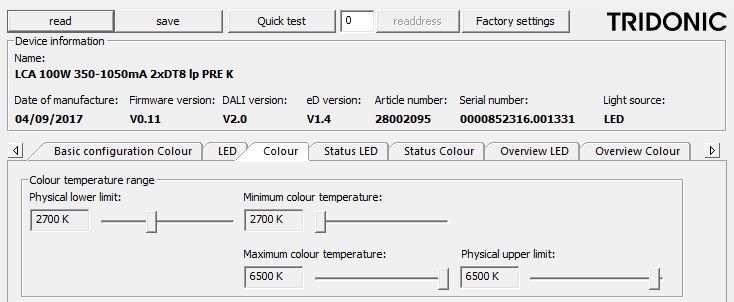
Manual LCA PRE / LC EXC | 03-2020 | 2.9 | en

Description of key features

3.5. Operating Window Multichannel
The new Multichannel devices (DT 8 and 2/4 CH DT 6) differ from the normal standard LED Driver in certain points.
They make it possible to use more than one channel at one device. Due to this fact a different view of the operating window was
choosen.
All Multichannel devices are equipped with an I-Select 2 Interface. The current set with this plug will be used for all channels with the
same value.

3.5.1. Multichannel – DT8 - LCA 50W 350–1050mA DT8 lp PRE
This device has 1 DT8 output.
Both channels can be programmed with the max. output current as defined in the datasheet.
All multi channel devices are equipped with an I-SELECT 2 Interface. The current set with this plug will be used for all channels with
the same value.
The colour can be set via DT8 colour temperature commands and colourSWITCH (see colourSWITCH, p. ).

...

c                                                                                                                               14 / 72
Manual LCA PRE / LC EXC | 03-2020 | 2.9 | en

Description of key features

This graph shows the operating window of the device.

                                                           Operating window 100 %
                                                          Operating window dimmed

This graph shows the output power window of the device.

                                                           Operating window 100 %
                                                          Operating window dimmed

c                                                                                   15 / 72
Manual LCA PRE / LC EXC | 03-2020 | 2.9 | en
Description of key features
Make sure that the LED Driver is operated within the given window under all operating conditions.
Special attention needs to be paid at dimming and DC emergency operation as the forward voltage of the connected LED modules
varies with the dimming level,
due to the implemented amplitude dimming technology.
Coming below the specified minimum output voltage of the LED Driver may cause the device to shut-down.
3.5.2. Multichannel – 2xCH - LCA 50W 350–1050mA 2xCH lp PRE
This device has two DT 6 output channels. Both channels can be programmed and operated separately.
There are 2 DALI addresses available and every channel can be programmed via DALI with its own current settings.
Both channels can be programmed with the max. output current as defined in the datasheet.
All Multichannel devices are equipped with an I-Select 2 Interface. The current set with this plug will be used for all channels with the
same value.
This graph shows the operating window of the device.
Operating window 100 %
Operating window dimmed
When using both channels, the second graph has to be used because the power of the device will be reduced depending on the
current and forward voltage selection.
Make sure not to overload the device with high output currents on both channels. Always calculate summary values for current and
forward voltage for our used channels.
If a wrong setup was stored and the driver would be overloaded, the second Channel (2) will reduce the output power automatically to
protect the device.
c 16 / 72Manual LCA PRE / LC EXC | 03-2020 | 2.9 | en Description of key features 3.5.3. Multichannel – LCA 100W 350–1050mA 2xDT8 lp PRE This device has 2 DT8 outputs. Output 1+2 will be seen as one DT8 channel and ouput 3+4 will be seen as the other DT8 channel. The colour can be set with color temperature commands via DALI. The device has two DT8 DALI addresses. The current can be programmed via DALI for all four output channels with the max. output current as defined in the datasheet. All multichannel devices are equipped with an I-Select 2 Interface. The current set with this plug will be used for all channels with the same value. ... c 17 / 72
Manual LCA PRE / LC EXC | 03-2020 | 2.9 | en

Description of key features

This graph shows the operating window of the device.

                                                                 Operating window 100 %
                                                                Operating window dimmed

When using both channels, you have to use the second graph, because the power of the device will be reduced depending on your
current and forward voltage selection.
Make sure not to overload the device with to high output currents on both channels. Always calculate summary values for current and
forward voltage for your used channels.
If a wrong setup was stored and the driver would be overloaded, the second output Channel (2) and the fourth output Channel (4) will
reduce the output power automatically to protect the device.
Channel 2+4 is the same colour and so an indication is clearly visible while reducing the output power.

c                                                                                                                         18 / 72
Manual LCA PRE / LC EXC | 03-2020 | 2.9 | en Description of key features 3.5.4. Multichannel – 4xCH - LCA 100W 350–1050mA 4xCH lp PRE This device has four DT 6 output channels. All channels can be programmed and operated separately. There are 4 DALI addresses available and every channel can be programmed via DALI with its own current settings. All channels can be operated with the max. output current as defined in the datasheet. All Multichannel devices are equipped with an I-Select 2 Interface. The current set with this plug will be used for all channels with the same values. ... c 19 / 72
Manual LCA PRE / LC EXC | 03-2020 | 2.9 | en

Description of key features

This graph shows the operating window of the device.

                                                                 Operating window 100 %
                                                                Operating window dimmed

When using all four channels you have to use the second graph, because the power of the device will be reduced depending on your
current and forward voltage selection.
Make sure not to overload the device with to high output currents on both channels. Always calculate summary values for current and
forward voltage for your used channels.
If a wrong setup was stored and the driver would be overloaded, the second output Channel (2) and the fourth output Channel (4) will
reduce the output power automatically to protect the device.

c                                                                                                                         20 / 72
Manual LCA PRE / LC EXC | 03-2020 | 2.9 | en
Description of key features
_ Green area: The green area is an operation with up to four channels (this table also refers to the table on page 2).
_ Orange area: The orange area is then the first area thermally limited by the 3 – 4 channel operation.
_ Red area: The red area is the area that is thermally even more limited by the 3 – 4 channel operation.
_ Red dotted area: The red dotted area is the area that is thermally very strong limited by the 4 channel operation.
I NOTICE
By using more channels and higher output power, the temperature range could be decreased very strongly. Details see in the
lifetime table.
...
c 21 / 72Manual LCA PRE / LC EXC | 03-2020 | 2.9 | en
Description of key features
With increasing performance and use of all channels, the temperature range is severely limited. Details can be taken from the
"Expected life-time" table.
Output current
(CH1 + CH2 + CH3 +
Type CH4) ta 30 °C 35 °C 40 °C 50 °C 60 °C
LCA 100W 350-1050mA 4xCH 700 – 1,400 mA tc 50 °C 55 °C 60 °C 70 °C 80 °C
lp PRE
Life-time >100,000 h >100,000 h >100,000 h 95,000 h 50,000 h
1,400 – 1,800 mA tc 55 °C 60 °C 65 °C 75 °C 85 °C
Life-time >100,000 h >100,000 h >100,000 h 50,000 h 25,000 h
1,800 – 2,100 mA tc 60 °C 65 °C 70 °C 80 °C 90 °C
Life-time >100,000 h 90,000 h 65,000 h 40,000 h 25,000 h
2,100 – 2,800 mA tc 60 °C 65 °C 70 °C 85 °C -
Life-time 80,000 h 55,000 h 40,000 h 20,000 h -
2,800 – 3,600 mA tc 65 °C 70 °C 75 °C - -
Life-time 40,000 h 30,000 h 20,000 h - -
3,600 – 4,200 mA tc 70 °C 75 °C - - -
Life-time 20,000 h 15,000 h - - -
...
c 22 / 72Manual LCA PRE / LC EXC | 03-2020 | 2.9 | en
Compatibility between module and LED Driver
There are two stages involved in the check for compatibility between the LED module and the LED Driver.
_ The requirements for operating together can be checked by comparing the data sheets
_ Subsequent practical tests can ensure that there are no unexpected problems during actual operation
4.1. Comparison of data sheet values with a 4-point guideline
Different values for the two devices need to be considered when comparing the data sheets. The following table shows which values
are involved and which requirements they must meet.
Comparison Value in Value in LED
of… light module Driver Detailed procedure
(1) Current Imax = Output current _ Determine forward current of LED module
_ Check whether LED Driver can be operated with the same output current
Max. DC >= Output current
forward + tolerances _ Check whether max. DC forward current of LED module is greater than or
current equal to output current of LED Driver (including tolerances)
½ CAUTION!
The max. DC forward current can be temperature dependent!
Refer to the derating curve of the LED module data sheet (see Reference
list, p. 72).
continue... ->
...
c 23 / 72Manual LCA PRE / LC EXC | 03-2020 | 2.9 | en
Compatibility between module and LED Driver
Comparison Value in Value in LED
of… light module Driver Detailed procedure
(2) Voltage Min. forward > Min. output _ Check whether voltage range of LED module is completely within the
voltage voltage voltage range of LED Driver
Max. forward < Max. output
voltage voltage ½ CAUTION!
The forward voltage is temperature dependent!
Refer to the Vf/tp diagram in the data sheet (see Reference list, p. 72).
Min. forward > Min. output
voltage voltage
I NOTICE
@ min. To ensure full dimming performance the forward voltage of the LED
dimlevel module at min. dim level must be greater than or equal to the min. output
voltage of the driver (PRE only).
_ Determine the forward voltage of the LED module at lowest dim level
_ In case there is no data available for the LED module at lowest dim level:
take the min. forward voltage minus 20 % as an approximation
_ Check whether the forward voltage of the LED module is greater than or
equal to the min. output voltage of the driver
(3) LF Max. >= Output LF _ Check whether max. permissible LF current ripple of LED module is
current permissible current ripple greater than or equal to output LF current ripple of LED Driver
ripple LF current ( Max. output _ Check whether max. permissible peak current of LED module is greater
peak current permissible current peak than max. output current peak of LED Driver
peak current
...
c 24 / 72Manual LCA PRE / LC EXC | 03-2020 | 2.9 | en Compatibility between module and LED Driver 4.2. Application of the 4-point guideline The compatibility check with the 4-point guideline is shown here using two examples. 4.2.1. Example 1 Comparison data for LED Driver LED Driver Designation LCI 20W 350mA-900mA TOP C Manufacturer TRIDONIC Data sheet values of LED Driver Output current 500 mA Output current tolerance ±5% Min. output voltage 18 V (1) Max. output voltage 40 V (1) Output LF current ripple ±2% Max. output current peak 600 mA (1) Values at 500mA c 25 / 72
Manual LCA PRE / LC EXC | 03-2020 | 2.9 | en

Compatibility between module and LED Driver

Comparison data for LED module

      LED module

      Designation                           Fictitious LED module

      Manufacturer                          Other manufacturer

      Data sheet values of LED module

      Forward current                                                     500 mA

      Max. DC forward current                                             1,050 mA

      Typ. forward voltage                                                33 V ±10 % (1)

      Min. forward voltage                                                29.7 V (1)

      Max. forward voltage                                                36.3 V (1)

      Max. permissible LF current ripple                                  630 mA

      Max. permissible peak current                                       1,500 mA

(1)    Values at 500mA

Questions
      _ Are the two components mutually compatible?
      _ Can the required luminous flux of 1,510 lm be achieved with this combination?

...

c                                                                                          26 / 72
Manual LCA PRE / LC EXC | 03-2020 | 2.9 | en
Compatibility between module and LED Driver
Procedure
Comparison of data sheet values
Value
Comparison Value in in LED
of… light module Driver Result Explanation
(1) Current 500 mA = 500 mA _ To produce a luminous flux of 1,510 lm the light module must be
operated with a forward current of 500 mA.
_ The LED Driver can be set so that it delivers precisely this value of
500 mA as the output current (with a resistance of 49.90 k).
1,050 mA >= 525 mA _ The output current of the LED Driver including tolerances (500 mA + 5
% = 525 mA) is less than or equal to the max. DC forward current of the
light module (1,050 mA).
(2) Voltage 29.7 V > 18 V _ The voltage range of the light module (29.7 V - 36.3 V) lies
completely within the voltage range of the LED Driver (18 V -
36.3 V < 40 V 40.0 V).
(3) LF 630 mA > 535.5 _ The Output LF current ripple (2 % of output current plus tolerances:
current mA [500 mA + 5 %] x 1.02 = 535.5 mA) of the LED Driver is less than the
ripple max. permissible LF current ripple of the LED module (630 mA).
(4) Max. 1,500 mA > 600 _ The max. output current peak of the LED Driver (500 mA + 20 % =
peak current mA 600 mA) is less than the max. permissible peak current with which the
light module can be operated (1,500 mA).
Result
All the values meet the requirements. The components are mutually compatible.
c 27 / 72Manual LCA PRE / LC EXC | 03-2020 | 2.9 | en Compatibility between module and LED Driver 4.2.2. Example 2 Comparison data for LED Driver LED Driver Designation LCI 20W 350mA-900mA TOP C Manufacturer TRIDONIC Data sheet values of LED Driver Output current 500 mA Output current tolerance ±5% Min. output voltage 18 V (1) Max. output voltage 40 V (1) Output LF current ripple ±2% Max. output current peak 600 mA (1) Values at 500mA Comparison data for LED module LED module Designation Fictitious LED module Manufacturer Other manufacturer Data sheet values of LED module Forward current 500 mA Max. DC forward current 1,050 mA Typ. forward voltage 39.5 V ±10 % (1) Min. forward voltage 35.55 V (1) Max. forward voltage 43.45 V (1) Max. permissible LF current ripple 630 mA Max. permissible peak current 1,500 mA (1) Values at 500mA c 28 / 72
Manual LCA PRE / LC EXC | 03-2020 | 2.9 | en

Compatibility between module and LED Driver

Questions
      _ Are the two components mutually compatible?
      _ Can the required luminous flux of 1,800 lm be achieved with this combination?

...

c                                                                                       29 / 72
Manual LCA PRE / LC EXC | 03-2020 | 2.9 | en
Compatibility between module and LED Driver
Procedure
Comparison of data sheet values
Value
Comparison Value in in LED
of… light module Driver Result Explanation
(1) Current 500 mA = 500 mA _ To produce a luminous flux of 1,800 lm the light module must be
operated with a forward current of 500 mA.
_ The LED Driver can be set so that it delivers precisely this value of
500 mA as the output current (with a resistance of 49.90 k).
1,050 mA >= 525 mA _ The output current of the LED Driver including tolerances (500 mA +
5 % = 525 mA) is less than or equal to the max. DC forward current of
the light module (1,050 mA).
(2) Voltage 35.55 V > 18 V _ The voltage range of the light module (35.55 V - 43.45 V) is not within
the voltage range of the LED Driver (18 V - 40.0 V)
43.45 V < 40 V
(3) LF 630 mA > 535.5 _ The Output LF current ripple (2 % of output current plus tolerances:
current mA [500 mA + 5 %] x 1.02 = 535.5 mA) of the LED Driver is less than the
ripple max. permissible LF current ripple of the LED module (630 mA).
(4) Max. 1,500 mA > 600 mA _ The max. output current peak of the LED Driver (500 mA + 20 % =
peak current 600 mA) is less than the max. permissible peak current with which the
light module can be operated (1,500 mA).
Result
One of the values does not meet the requirements. The components are not mutually compatible.
...
c 30 / 72Manual LCA PRE / LC EXC | 03-2020 | 2.9 | en
Compatibility between module and LED Driver
4.3. Practical tests
Practical tests are used to ensure fault-free operation of the light module and LED Driver. The following aspects must be checked.
4.3.1. Technical aspects
_ Transient behaviour
_ Colour shift
_ Connection during operation
_ Parasitic capacitance
4.3.2. Visual aspects
_ Flickering
_ Stroboscopic effect (video applications)
_ Dimming behaviour (PRE only)
_ Colour change/stability
_ Luminous flux
4.3.3. Conditions
When conducting the tests the following conditions must be considered:
_ All tolerances
_ Entire temperature range
_ Different output voltage ranges (incl. no load)
_ Entire dimming range (PRE only)
_ Short circuit
I NOTICE
If the values are slightly over or under the specified threshold values or if there are any other concerns or questions please contact
Technical Support: techservice@tridonic.com
...
c 31 / 72Manual LCA PRE / LC EXC | 03-2020 | 2.9 | en
Installation notes
I NOTICE
The cabling, wiring and mounting for a LED driver varies depending on the design and manufacturer of the LED module.
The following description should therefore not be viewed as comprehensive installation instructions but merely as important
general information.
To obtain further information, proceed as follows:
_ Read the documentation provided by the lamp manufacturer. Follow the guidelines and instructions of the lamp
manufacturer!
_ Observe all relevant standards. Follow the instructions given in the standards!
5.1. Safety information
½ WARNING!
_ Comply with the general safety instructions (see General safety instructions, p. 5) !
_ To avoid failures due to ground faults protect the wiring against mechanical loads from sharp-edged metal parts (e.g. cable
penetrations, cable holders, metal frames, etc.
_ Electronic LED Driver from Tridonic are protected for a maximum of 48 hour against overvoltage of up to 320 V. Make sure
that the LED Driver is not exposed to overvoltages for long periods!
_ Electronic LED Driver LCA PRE, LC EXC from Tridonic have type of protection IP 20. Comply with the requirements for this
type of protection!
...
c 32 / 72Manual LCA PRE / LC EXC | 03-2020 | 2.9 | en Installation notes 5.2. Function of the earth terminal The earth connection is conducted as protection earth (PE). The LED Driver can be earthed via earth terminal or metal housing (if device has metal housing). If the LED Driver will be earthed, protection earth (PE) has to be used. There is no earth connection required for the functionality of the LED Driver. Earth connection is recommended to improve following behaviour. _ Electromagnetic interferences (EMI) _ LED glowing at standby _ Transmission of mains transients to the LED output In general it is recommended to earth the LED Driver if the LED module is mounted on earthed luminaire parts respectively heat sinks and thereby representing a high capacity against earth. 5.2.1. Avoiding residual LED glow on standby Residual LED glow on standby may occur as a result of capacitive leakage currents from the LED module onto earthed luminaire parts (such as the heat sink). This mainly affects high-efficiency LED systems with large surface areas installed in luminaires with protection class 1. The topology has been improved so that residual LED glow can be virtually eliminated by earthing the devices. I NOTICE If the LED driver cannot be earthed or if earthing is not desired, residual LED glow can be minimised by adequate insulation (for example by using heat-conducting double-sided insulation foil). 5.2.2. Avoiding the transfer of mains transients to the LED output The transfer of mains transients to the LED output presents a problem for many LED driver topologies currently on the market, and TRIDONIC devices may be affected. Voltage peaks at the input of the LED driver may be transferred to the output of the device where they lead to differences in potential between the LED output and earthed luminaire parts. These differences in potential may result in flashovers if the insulation is inadequate or if the creepage and clearance distances are too small. Flashovers will cause the LED module to fail. Earthing the LED driver attenuates voltage peaks and reduces the likelihood of flashovers. The precise degree of attenuation depends on the capacitance of the LED module with respect to earth. If voltages at the output are higher than 0.5 kV, it is mentioned in the data sheet. c 33 / 72
Manual LCA PRE / LC EXC | 03-2020 | 2.9 | en

Installation notes

Figure: Voltage peaks for LED driver without earthing (left) and with earthing (right)

 I NOTICE
      Irrespective of whether the LED driver is earthed or not, LED modules must be insulated in accordance with the requirements of
      the luminaire protection class. Improved insulation of the LED module can also reduce the likelihood of flashovers.

...

c                                                                                                                             34 / 72
Manual LCA PRE / LC EXC | 03-2020 | 2.9 | en Installation notes 5.3. Routing the wires 5.3.1. Tests I NOTICE The performance of the prescribed tests and compliance with relevant standards are the responsibility of the luminaire manufacturer. The following descriptions merely indicate the most important tests and are no substitute for a full research of the relevant standards. 5.3.2. Insulation and dielectric strength testing of luminaires LED driver for lamps are sensitive to high-voltage transients. This must be taken into consideration when subjecting luminaires to routine testing during manufacture. According to IEC 60598-1 Annex Q (for information only!) and ENEC 303-Annex A, each luminaire should be subjected to an insulation test for 1 second at 500 V DC. The test voltage is applied between the linked phase/neutral conductor terminal and the protective earth terminal. The insulation resistance must be at least 2 megaohm. As an alternative to measuring the insulation resistance, IEC 60598-1 Annex Q describes a dielectric strength test at 1500 V AC (or 1.414 x 1,500 V DC). To avoid damaging electronic LED Driver, this dielectric strength test should be performed exclusively for type testing. This test should certainly not be used for routine testing. I NOTICE Tridonic recommends performing an insulation test because a dielectric strength test may damage the device irreparably. 5.3.3. Type testing Type testing of the luminaire is performed according to IEC 60598-1 Section 10. The wiring for protection class 1 luminaires is tested at a voltage of 2xU + 1,000 V. In order not to overload the LED Driver all the inputs and outputs of the LED Driver are connected to one another. Uout is used for measuring the voltage for luminaires with LED Driver with U out > 250 V: For Uout 480 V the voltage for the type test is 2000 V. (Routine testing is always performed at 500 V DC) 5.3.4. Wiring I NOTICE The wiring procedure is device specific. Further information about wiring, wire cross sections and the length of stripped off insulation can be found in the data sheet. c 35 / 72
Manual LCA PRE / LC EXC | 03-2020 | 2.9 | en

Installation notes

Wiring guidelines
 _ The cables should be run separately from the mains connections and mains cables to ensure good EMC conditions.
 _ The LED wiring should be kept as short as possible to ensure good EMC. The max. secondary cable length is 2 m (4 m circuit),
   this applies for LED output as well as for I-select and temperature sensor.
 _ Depending on the design of the luminaire it may be possible to improve the radio interference properties by earthing the
   device at the earth connection.
 _ The LED driver has no inverse-polarity protection on the secondary side. Wrong polarity can damage LED modules with no
   inverse-polarity protection.

Wiring the plug-in terminal

 _ Use solid wire or stranded wire with the correct cross-section
 _ Strip off correct length of insulation; you may need to twist the tool slightly
 _ If stranded wire is used: push onto the terminal from above to be able to insert the wire
 _ Insert the bare end into the terminal

Detaching the plug-in terminal

 _ Push onto the terminal from above to release the wire
 _ Pull out the wire at the front

5.4. External fuse for DC operation
The internal fuse of an LED Driver is not rated for DC operation. Because of this, an additional external fuse must be used if an LED
Driver is operated on a DC network.

Proceed as follows:

 _ Connect the external fuse to the line labeled "+" which is between the DC power supply and the input terminal of the LED
   Driver
 _ Only use an external fuse with suitable parameters.

For LED Drivers with a power of 25-150 watts the following values are recommended:

 _ Rated voltage: 250 V
 _ DC rated power: 1 A - 3 A Time-Lag (SLO-Blo®)

Tridonic recommends the following external fuse:

 _ 477 Series, 5 × 20 mm, Time-Lag (Slo-Blo®) Fuse Rating 3.15 A

c                                                                                                                             36 / 72
Manual LCA PRE / LC EXC | 03-2020 | 2.9 | en

Installation notes

5.5. Maximum loading of circuit breakers
5.5.1. Importance of maximum loading
A circuit breaker is an automatically operated electrical switch that protects an electrical circuit from damage caused by overload or
short circuit. Unlike a fuse that must be replaced if it triggers, a circuit breaker can be reset (either manually or automatically) and
used further. Circuit breakers are available in different sizes and with different technical data.

The inrush current is a short increased peak current that occurs when an electronic control gear is switched on.

In electrical installations, numerous control gear are connected to one circuit breaker. The maximum loading of a circuit breaker
indicates how many control gear can be connected to the circuit breaker without triggering the circuit breaker because of the
summation of the different inrush currents. The value is calculated through simulation programs based on the circuit breakers
characteristic.

Information about the maximum loading can be found in Tridonic data sheets. The following table shows the data for LCA 50W
100-400mA one4all lp PRE as an example

 Automatic circuit breaker type                  C10           C13   C16    C20      B10     B13      B16     B20       Inrush current

 Installation Ø                                   1.5         1.5     2.5    2.5      1.5    1.5      2.5      2.5       Imax       time
                                                 mm2         mm2     mm2    mm2      mm2     mm2     mm2      mm2

 LCA 50W 100-400mA one4all lp PRE                 18           26    28     34           9    13       14        17     22.4 A     176 µs

5.5.2. Calculation of maximum loading
Tripping characteristics of circuit breakers
The load at which a circuit breaker triggers is defined by the height and the duration of the applied current.
The following table shows exemplary values for different circuit breakers (B10, B13, B16, B20).

 Duration               Current B10                    Current B13                 Current B16                Current B20
 [µs]                   [Apeak]                        [Apeak]                     [Apeak]                    [Apeak]

 100                    700                            910                         1,120                      1,400

 200                    260                            338                         416                        520

 300                    177                            230.1                       283                        354

 400                    145                            188.5                       232                        290

 500                    122                            158.6                       195                        244

 600                    110                            143                         176                        220

 700                    102                            132.6                       163                        204

c                                                                                                                                37 / 72
Manual LCA PRE / LC EXC | 03-2020 | 2.9 | en
Installation notes
800 97 126.1 155 194
900 93 120.9 149 186
1000 90 117 144 180
The combination of both parameters can also be displayed graphically. This results in the tripping characteristic for a certain circuit
breaker.
Current [A]
Duration [µs]
I NOTICE
Information about the specific tripping characteristics of a circuit breaker must be requested from the respective manufacturer !
Calculation of the inrush current
The inrush current of a control gear is also defined by its duration and its height. The duration is typically measured as the time
between 10 % of maximum current (ascending) and 50 % of maximum current (descending).
The following illustration shows the inrush current of a single control gear:
If several control gear are connected to one circuit breaker, the individual inrush currents add up.
c 38 / 72Manual LCA PRE / LC EXC | 03-2020 | 2.9 | en Installation notes Implementation of the simulation The above-mentioned parameters, height and duration of the current pulse in both the circuit breaker and the control gear, are entered into the simulation program. The result of the simulation is presented in graphical form. The different elements have the following meaning: _ Circuit breaker: B10, B13, B16, B20 (solid line) represent the tripping characteristics of different circuit breakers. _ Inrush current: The dotted lines represent different inrush currents. The index of a point signifies the number of LED Driver, that is, point 1 represents the result for 1 LED Driver, point 2 the result for 2 LED Driver, etc. The simulation results can be read as follows: _ The crossing of the two lines shows the maximum value for the selected combination of circuit breaker and inrush current. _ The index of the point at this maximum value shows the max. number of ballasts. The following example shows the maximum number of control gear at four different circuit breakers: _ max. 5 devices at circuit breaker B10 (green tripping characteristic) _ max. 7 devices at circuit breaker B13 (pink tripping characteristic) _ max. 9 devices at circuit breaker B16 (red tripping characteristic) _ max. 12 devices at circuit breaker B20 (blue tripping characteristic) c 39 / 72
Manual LCA PRE / LC EXC | 03-2020 | 2.9 | en

Installation notes

 I NOTICE
      The results of different simulations can only be compared if all of the relevant factors are the same. The following points can
      influence the results:

      _ Tripping characteristic used for the circuit breakers
      _ Definition used for the duration of the inrush current (Tridonic: 10-50 %)
      _ Gear used for the measurement of the inrush current (especially important: Which electrolytic capacitor is installed in the LED
        Driver)
      _ Considering a safety buffer (Tridonic: +20 % for the electrolytic capacitor )
      _ Considering different system impedances
      _ Switch-on point used: should always be at max. input voltage
      _ Adopted cable lengths and cable data (Tridonic: Cable length 40 cm; Resistivity: 0.0172 * mm 2 / m; inductance: 5 nH / cm;
        terminal resistance: 2 m)
      _ The modeling of the control gear is performed from the input to the bus voltage electrolytic capacitor. For inductance the
        saturation values must be used.

...

c                                                                                                                                  40 / 72
Manual LCA PRE / LC EXC | 03-2020 | 2.9 | en
Functions
6.1. corridorFUNCTION V2 (PRE only)
6.1.1. Description
The corridorFUNCTION enables the illuminance to be linked to the presence or absence of people. A conventional relay motion sensor
is connected. The luminous intensity is increased when a person enters the room. When the person leaves the room the motion sensor
switches off after a certain delay and the luminous intensity is automatically reduced.
The corridorFUNCTION is particularly beneficial in applications in which light is needed round the clock for safety reasons, for
example in public buildings, large apartment complexes, car parks, pedestrian underpasses and underground railway stations. Since
the luminous intensity only has to be increased when there is a demand for light the corridorFUNCTION offers effective lighting
management and helps saving energy and costs. Another benefit of the corridorFUNCTION is the enhanced convenience of automatic
lighting control.
½ CAUTION!
To ensure correct operation a sinusoidal mains voltage with a frequency of 50 Hz or 60 Hz is required at the control input.
Special attention must be paid to achieving clear zero crossings. Serious mains faults may impair the operation of switchDIM and
corridorFUNCTION.
Profile settings:
Standard profile for activating via 230V on the interface terminal DA/N - DA/L for 5 minutes is "Never off"
The LED Drivers have different profiles so they can provide the best possible performance in a range of conditions. The profiles are
defined by a series of values:
1. Fade-in time: the time that starts as soon as the presence of a person is detected. During the fade-in time the luminous intensity
is faded up to the presence value (default: 0s).
2. Run-on time: the time that starts as soon as the presence of a person is no longer detected. If the presence of a person is
detected again during the run-on time the run-on time is restarted from zero. If no presence is detected during the run-on time
the fade time is started as soon as the run-on time expires.
3. Fade time: the time during which the luminous intensity is faded from the presence value to the absence value (default: 30 s).
4. Switch off delay: the time during which the absence value is held before the lighting is switched off. Depending on the profile
selected the switch-off delay may have different values or may not be defined (default: "Never Off").
5. Absence value: the luminous intensity when there is no person present (default: 10 %).
6. Presence value: the luminous intensity when persons are present (default: 100 %).
c 41 / 72Manual LCA PRE / LC EXC | 03-2020 | 2.9 | en Functions Variable switch-off times The profiles and their values can be freely adjusted. The values can be adjusted via a connection to a DALI bus. 6.1.2. Commissioning Activating the corridorFUNCTION Procedure by means of the mains voltage Activating the corridorFUNCTION is simple. If an a.c. voltage of 230 V is applied to the digital interface of the LED Driver for a period of at least 5 minutes the LED Driver detects the corridorFUNCTION and automatically activates it. Activation is required only once per device. There are three procedures for activating by means of the mains voltage. The requirements are the same in each case. Requirements: _ The LED Driver is correctly installed in the luminaire _ Input voltage is applied _ A motion sensor is connected to information DA/N or DA/L Procedure Version 1: _ Remain in the activation range of the motion sensor for more than 5 minutes -> The motion sensor detects movement and switches on -> The corridorFUNCTION is activated automatically after 5 minutes -> The light value switches to presence level (default: 100 %) Procedure Version 2: _ Set the run-on time on the motion sensor to a value greater than 5 minutes _ Remain in the activation range of the motion sensor for a short time -> The motion sensor detects movement and switches on -> The corridorFUNCTION is activated automatically after 5 minutes -> The light value switches to presence value (default: 100 %) _ Reset the run-on time of the motion sensor to the required value Procedure Version 3: Only possible if the motion sensor offers a manual override option _ Set the slide switch on the motion sensor to the "Never-Off" function _ Wait 5 minutes -> The corridorFUNCTION is activated automatically after 5 minutes -> The light value switches to presence value (default: 100 %) _ Reset the slide switch on the motion sensor to the "automatic" function Procedure via the masterCONFIGURATOR The corridorFUNCTION can also be activated via the masterCONFIGURATOR. Further information can be found in the masterCONFIGURATOR manual (see Reference list, p. 72). c 42 / 72
Manual LCA PRE / LC EXC | 03-2020 | 2.9 | en

Functions

Deactivating the corridorFUNCTION
If the corridorFUNCTION is activated the LED Driver is controlled only by motion. To operate the LED Driver via DALI, DSI or
switchDIM the corridorFUNCTION must be deactivated.

Procedure via mains

      _ Connect mains voltage push button to the terminal marked DA/L
      _ Connect neutral conductor to the terminal marked DA/N
      _ Press the push button 5 times within 3 seconds

Procedure via DALI/DSI

      _ Send 5 DALI or DSI commands within 3 seconds to the LED Driver

Procedure via masterCONFIGURATOR
If the corridorFUNCTION was activated via the masterCONFIGURATOR it can be deactivated as follows:

      _ Send 5 DALI or DSI commands within 3 seconds to the LED Driver

Adjusting the values of the corridorFUNCTION
The values of the corridorFUNCTION can be individually adjusted. The values are set via a DALI USB on the bus and by entering
special DALI commands via the masterCONFIGURATOR.

Further information can be found in the masterCONFIGURATOR manual (see Reference list, p. 72).

...

c                                                                                                                          43 / 72
Manual LCA PRE / LC EXC | 03-2020 | 2.9 | en Functions 6.1.3. Installation Requirements: _ The LED Driver is correctly installed in the luminaire and cabled on the power supply side _ A motion sensor is installed in the lighting system _ The motion sensor is connected to the LED Driver Procedure: _ Connect the neutral conductor (N) to terminal DA/N on the LED Driver _ Connect the output of the motion sensor (switched phase) to terminal DA/L on the LED Driver Wiring versions: c 44 / 72
Manual LCA PRE / LC EXC | 03-2020 | 2.9 | en

Functions

Benefits:
Control can be changed at any time to a digital control signal (DSI or DALI) without having to change the luminaire or provide an
additional control line

 ½ CAUTION!
      Use conventional relay motion sensors!
      Electronic motion sensors (Triac) are not suitable because of their technical design.

 ½ CAUTION!
      Do not use glow switches!
      Glow switches may affect the control.

 ½ CAUTION!
      Make sure that the control line (L') of the motion sensor is connected to terminal DA/L and the neutral conductor (N) to terminal
      DA/N.

 ½ CAUTION!
      For five-pole wiring the neutral conductor must be connected to DA/N.
      This prevents 400 V being applied between adjacent terminals if a different phase is used for the control input.

 I NOTICE
      For large installations, supply to the LED Driver may be split among several phases (L1, L2, L3).
      Any phase can be used for the control input .
      Any number of motion sensors can be connected in parallel.

...

c                                                                                                                                45 / 72
Manual LCA PRE / LC EXC | 03-2020 | 2.9 | en
Functions
6.2. DSI (PRE only)
6.2.1. Description
DSI (Digital Serial Interface) enables DSI control gear to be controlled. The DSI line can be wired separately via a two-core cable or
together with the mains cable in a five-core cable. Communication is not impaired by the mains cable. In contrast to DALI, there is no
individual addressing of the ballasts with DSI.
DSI offers a series of benefits:
_ Expansion options via submodules, for example in combination with daylight control or additional switch modules
_ Wiring: Simple wiring with five pole standard cables and line length of up to 250 metres
_ Wiring: Polarity-free control lines can be used for mains and control lines
_ Wiring: Multiple wiring possibilities (star, series and mixed wiring)
_ Unaffected by electrical interference: Uniform light level from the first to the last light source
_ reverse polarity protected connection: can be connected with any polarity
The main benefits of DSI are the optimisation of energy consumption of extensive groups of luminaires (e.g. in sports stadiums and
factories).
6.2.2. Commissioning
I NOTICE
If the corridorFUNCTION is activated the LED Driver is controlled only by motion. To operate the LED Driver via DALI, DSI or
switchDIM the corridorFUNCTION must be deactivated.
Further information can be found in the DALI Handbook (see Reference list, p. 72).
...
c 46 / 72Manual LCA PRE / LC EXC | 03-2020 | 2.9 | en Functions 6.3. switchDIM (PRE only) 6.3.1. Description With the switchDIM function it is possible to use the mains voltage as a control signal. The phase of a simple standard mains voltage push button is connected to the terminal marked DA/L and the neutral conductor is connected to the terminal marked DA/N. Using the function is easy and convenient: _ A short press (50-600 ms) switches the device on or off _ A long press (> 600 ms) fades the connected operating device alternately up and down (between 1 and 100 %). switchDIM is therefore a very simple form of lighting management. It also has a positive effect on material and labour costs. The device has a switchDIM memory function. This is used, among other things, for storing the last dimming value in the event of interruptions in the power supply. When power returns, the LED is automatically restored to its previous operating state and dimmed to the last value. ½ CAUTION! Glow switches are not approved for controlling switchDIM. Glow switches may cause the LED Driver to spontaneously switch on or off or make sudden changes in the dimming value. ½ CAUTION! To ensure correct operation a sinusoidal mains voltage with a frequency of 50 Hz or 60 Hz is required at the terminal. Special attention must be paid to achieving clear zero crossings. Serious mains faults may impair the operation of switchDIM and corridorFUNCTION. ½ CAUTIONS! A maximum number of 25 operating devices per switchDIM system should not be exceeded. If you have more devices please use DALI or DSI. 6.3.2. Commissioning I NOTICE If the corridorFUNCTION is activated the LED Driver is controlled only by motion. To operate the LED Driver via DALI, DSI or switchDIM the corridorFUNCTION must be deactivated. Using the switchDIM function switchDIM is operated by the mains voltage push button. c 47 / 72
Manual LCA PRE / LC EXC | 03-2020 | 2.9 | en

Functions

Procedure:

 _ Switch the device on/off by briefly actuating the push button or
 _ Dim the device by holding down the push button

Synchronising devices
If the devices in a system do not operate synchronously the devices must be synchronised, i.e. put in the same status (on/off).

Procedure:

 _ Hold down the push button for 10 seconds
   -> All devices will be synchronised to the same status
   -> LEDs will will be set to a uniform light value (approx. 50 %)
   -> The fading time will be set to it default value (approx. 3 seconds)

Changing the fading time
The default value for the fading time is approx. 3 seconds. It can be changed to approx. 6 seconds.

Procedure:

 _ Hold down the push button for 20 seconds
   -> After 10 seconds: all devices will be synchronised to the same status
   -> After 20 seconds: a fading time of approx. 6 seconds will be set
   -> LEDs will be set to a uniform light value (approx. 100 %)

Switching the LED Driver to automatic mode
In automatic mode the device detects which control signal (DALI, DSI, switchDIM, etc.) is connected and automatically switches to the
corresponding operating mode.

Procedure:

 _ Press the push button 5 times within 3 seconds

6.3.3. Installation
Wiring variants
There are two options for installing switchDIM: four-pole and five-pole wiring

c                                                                                                                            48 / 72
You can also read