User Manual Basic Configuration Dragon PTN Network Operation - Hirschmann ...
←
→
Page content transcription
If your browser does not render page correctly, please read the page content below
User Manual
 Basic Configuration
 Dragon PTN Network Operation

Dragon PTN Network Operation                        Technical Support
Release 01 05/2020             https://hirschmann-support.belden.eu.com
The naming of copyrighted trademarks in this manual, even when not specially indicated, should not
be taken to mean that these names may be considered as free in the sense of the trademark and
tradename protection law and hence that they may be freely used by anyone.

© 2020 Hirschmann Automation and Control GmbH

Manuals and software are protected by copyright. All rights reserved. The copying, reproduction,
translation, conversion into any electronic medium or machine scannable form is not permitted,
either in whole or in part. An exception is the preparation of a backup copy of the software for your
own use.

The performance features described here are binding only if they have been expressly agreed when
the contract was made. This document was produced by Hirschmann Automation and Control GmbH
according to the best of the company's knowledge. Hirschmann reserves the right to change the
contents of this document without prior notice. Hirschmann can give no guarantee in respect of the
correctness or accuracy of the information in this document.

Hirschmann can accept no responsibility for damages, resulting from the use of the network
components or the associated operating software. In addition, we refer to the conditions of use
specified in the license contract.

You can get the latest version of this manual on the Internet at the Hirschmann product site
(www.hirschmann.com).

Hirschmann Automation and Control GmbH
Stuttgarter Str. 45-51
72654 Neckartenzlingen
Germany

2                                                                     Dragon PTN Network Operation
                                                                                    Release 01 05/2020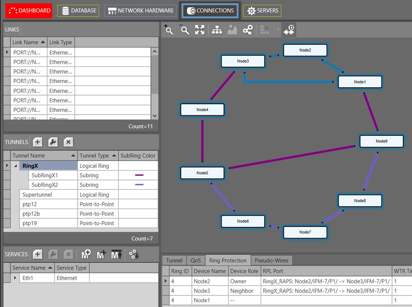
Contents

1.    INTRODUCTION ......................................................................................................... 7
      1.1          General ....................................................................................................... 7
      1.2          Supported Hardware, Firmware, Software ................................................... 7
      1.3          Manual References ...................................................................................... 7

2.    PHYSICAL LINKS: CONNECT ALL NODES INTO A WAN NETWORK .................................. 8
      2.1          General ....................................................................................................... 8
      2.2          Connect Optical Link via Fiber/SFP/XFP/QSFP+ ............................................. 8
      2.3          Connect Electrical Link via Copper/RJ45 ....................................................... 8

3.    HIPROVISION: DISCOVER NETWORK, DEPLOY DCN, CREATE LINKS ............................... 9
      3.1          General ....................................................................................................... 9
      3.2          DCN Channel ............................................................................................... 9
      3.3          DCN Bandwidth Profile ................................................................................ 9
      3.4          Link Capacity ............................................................................................. 10
      3.5          Amount of Protected Tunnels .................................................................... 10

4.    HIPROVISION: SET THE LAN PORTS IN YOUR NETWORK ............................................ 10

5.    HIPROVISION: CREATE MPLS-TP TUNNEL(S) .............................................................. 11
      5.1          General ..................................................................................................... 11
      5.2          Tunnel Creation ......................................................................................... 14
      5.3          Subrings .................................................................................................... 22
      5.4          Tunnel Modification .................................................................................. 25
      5.5          Monitor Protected Tunnel.......................................................................... 25
      5.6          Reporting .................................................................................................. 26
      5.7          Tunnel Actions: Swap Working Path ←→ Protection Path ........................... 26

6.    CSM REDUNDANCY .................................................................................................. 29

7.    SYNCE...................................................................................................................... 30
      7.1          General ..................................................................................................... 30
      7.2          Configuration ............................................................................................ 32
      7.3          Normal Clock Selection Process .................................................................. 34
      7.4          Operation .................................................................................................. 35

8.    PTP IEEE 1588V2 TRANSPARENT CLOCK .................................................................... 36
      8.1          General ..................................................................................................... 36
      8.2          IEEE 1588v2 within Dragon PTN.................................................................. 37
      8.3          Configuration ............................................................................................ 40
      8.4          Operation .................................................................................................. 41

9.    LOSS/DELAY/ASSURANCE MONITORING................................................................... 41

Dragon PTN Network Operation                                                                                                           3
Release 01 05/2020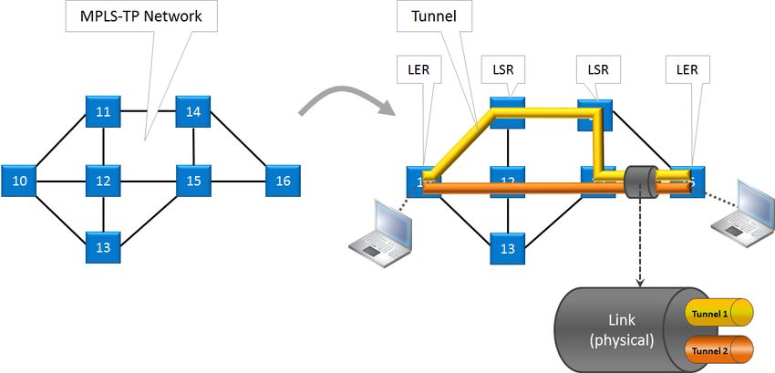
9.1 General ..................................................................................................... 41
9.2 Loss Measurement (=LM) ........................................................................... 41
9.3 Delay Measurement (=DM) ........................................................................ 45
9.4 Tunnel Ping ............................................................................................... 46
9.5 Tunnel Traceroute ..................................................................................... 49
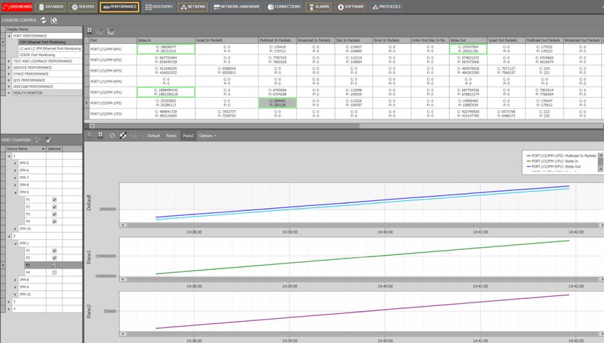
10. PERFORMANCE COUNTERS AND MONITORING......................................................... 50
10.1 General ..................................................................................................... 50
10.2 Port Performance ...................................................................................... 51
10.3 SyncE Performance .................................................................................... 55
10.4 IEEE 1588 Performance .............................................................................. 58
10.5 Health Monitor .......................................................................................... 59
11. TROUBLESHOOTING ................................................................................................. 60
11.1 Health Monitor .......................................................................................... 60
11.2 Port Mirroring ........................................................................................... 61
11.3 Monitoring: Multiproperty View ................................................................ 64
11.4 Devices Summary ...................................................................................... 66
12. PROTOCOL AND FEATURE SUPPORT MATRIX ............................................................ 68
13. ABBREVIATIONS ...................................................................................................... 72
List of figures
Figure 1 Dragon PTN Network Example ........................................................................................ 7
Figure 2 Link: DCN Bandwidth Profile ........................................................................................... 9
Figure 3 Ethernet Link: Link Capacity .......................................................................................... 10
Figure 4 LAN/WAN Settings......................................................................................................... 11
Figure 5 Tunnel Creation ............................................................................................................. 12
Figure 6 Point-to-Point Tunnels .................................................................................................. 13
Figure 7 MultiPoint Tunnels ........................................................................................................ 13
Figure 8 Logical Ring Tunnel ........................................................................................................ 13
Figure 9 Subring Tunnel............................................................................................................... 14
Figure 10 Create Tunnels............................................................................................................. 14
Figure 11 Tunnel - Device Selection ............................................................................................ 15
Figure 12 Tunnel - Link Selection................................................................................................. 15
Figure 13 Set Protection Mode of LSP ......................................................................................... 16
Figure 14 Tunnel HQoS / HQoS Application Priority ................................................................... 16
Figure 15 Protection Parameters ................................................................................................ 17
Figure 16 Example: Propagate Topology Change (=PTC) ............................................................ 19
Figure 17 Example: Main Ring + Subrings ................................................................................... 19
Figure 18 RingX (=Main Ring): Ring Protection Tab .................................................................... 20
Figure 19 SubringX1: Ring Protection / Topology Change Propagation Tab ............................... 20
4 Dragon PTN Network Operation
Release 01 05/2020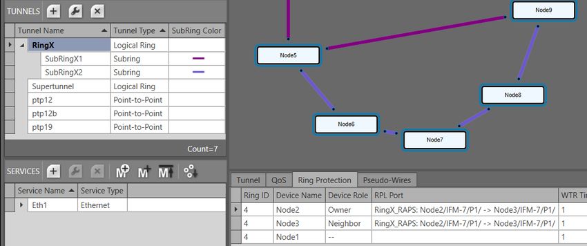
Figure 20 SubringX2: Ring Protection / Topology Change Propagation Tab ............................... 20
Figure 21 Share LSP: Shared/Non-Shared LSPs ........................................................................... 21
Figure 22 LSP Sharing Possible? .................................................................................................. 22
Figure 1 Logical Ring / Interconnection Nodes / Subring / Ladder Topology ............................. 22
Figure 2 Logical Ring / Subring Setup .......................................................................................... 23
Figure 3 Subring Colors................................................................................................................ 23
Figure 4 Ladder Topology Example 1 .......................................................................................... 24
Figure 5 Ladder Topology Example 2 .......................................................................................... 24
Figure 6 Ladder Topology: Not Allowed: Shared Link ................................................................. 24
Figure 7 Ladder Topology: Not Allowed: Only 2 Nodes in Subring ............................................. 25
Figure 8 Protected Tunnels: Protection Path, Blocked Port Indication: '//' ................................ 25
Figure 9 Protected Tunnel/Actions ............................................................................................. 26
Figure 10 Point-to-Point/Multipoint Action on Tunnel Window ................................................ 27
Figure 11 Ring/SubRing Action on Tunnel Window .................................................................... 28
Figure 12 Clear Command in the Node Action List ..................................................................... 28
Figure 13 Node with 2 CSMs, CSM Switchover Button ............................................................... 30
Figure 14 CSM Redundancy Status.............................................................................................. 30
Figure 15 Unidirectional/Bidirectional SyncE Examples.............................................................. 31
Figure 16 Bad SyncE Examples: Timing Loop .............................................................................. 32
Figure 17 SyncE Member Ports ................................................................................................... 32
Figure 18 SyncE Clock Recovery Ports ......................................................................................... 34
Figure 19 IEEE 1588v2 ................................................................................................................. 37
Figure 20 1588 Protocol Messages ............................................................................................. 37
Figure 21 1588 on Port and Node Level for LERs and LSRs ......................................................... 38
Figure 22 1588 Enabled: Transparent Clock Correction.............................................................. 39
Figure 23 1588 Not Enabled: No Clock Correction ...................................................................... 39
Figure 24 1588 Node Settings ..................................................................................................... 40
Figure 25 1588 Port Settings ....................................................................................................... 41
Figure 26 Assurance Wizard: Loss Measurement Configuration ................................................ 43
Figure 27 Loss Measurement in Operation ................................................................................. 44
Figure 28 Loss Measurement Result Values................................................................................ 44
Figure 29 Delay Measurement Result Values ............................................................................. 46
Figure 30 Assurance Wizard: Ping Measurement Configuration ................................................ 47
Figure 31 Tunnel Ping Result Values ........................................................................................... 48
Figure 32 Traceroute Results Overview ...................................................................................... 49
Figure 33 Performance Tab: Counter Control ............................................................................. 50
Figure 34 CSM Ethernet Port Monitoring.................................................................................... 52
Figure 35 L2 and L3 Ethernet Port Monitoring............................................................................ 54
Figure 36 CODIR Port Monitoring................................................................................................ 55
Figure 37 SyncE Monitoring ........................................................................................................ 56
Figure 38 IEEE 1588 Monitoring .................................................................................................. 58

Dragon PTN Network Operation                                                                                                                 5
Release 01 05/2020
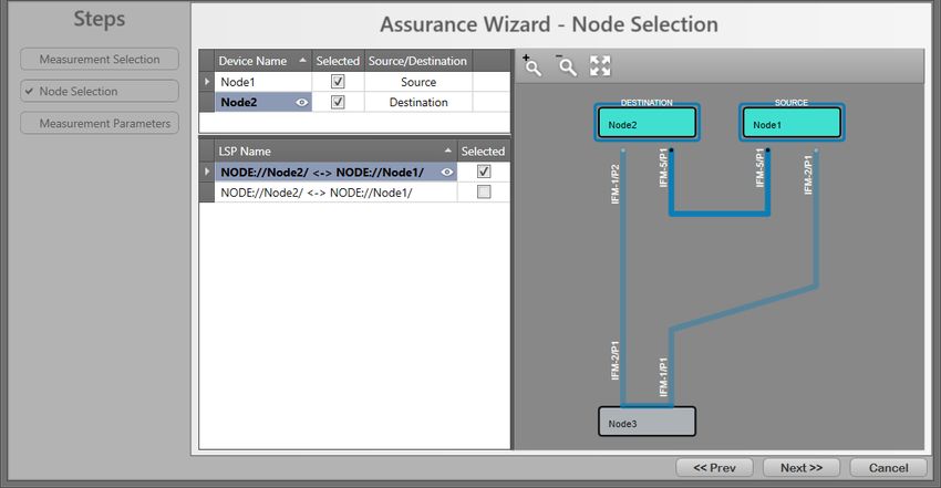
Figure 39 Health Monitor ............................................................................................................ 59
Figure 40 Port Mirroring.............................................................................................................. 61
Figure 41 Port Mirroring Icon ...................................................................................................... 61
Figure 42 Port Mirroring Wizard ................................................................................................. 62
Figure 43 Destination/Source Ports ............................................................................................ 62
Figure 44 Port Mirroring Sessions ............................................................................................... 63
Figure 45 Multiproperty View ..................................................................................................... 65
Figure 46 Multiproperty View: Filter Example ............................................................................ 66
Figure 47 Multiproperty View: Full Screen Results View + Export .............................................. 66
Figure 48 Devices Summary ........................................................................................................ 67

                                                             List of Tables
Table 1 Manual References ........................................................................................................... 7
Table 2 Tunnel Topologies and Protection.................................................................................. 12
Table 3 Tunnel Action Commands............................................................................................... 29
Table 4 Provisioned QL Ordered According Quality .................................................................... 33
Table 1 CSM Ethernet Port Monitoring Fields............................................................................. 52
Table 2 CODIR Port Monitoring Fields ......................................................................................... 55
Table 3 SyncE Monitoring 'System Information' Fields ............................................................... 56
Table 4 SyncE Monitoring 'Clock Information' Fields .................................................................. 57
Table 5 IEEE 1588 Monitoring Fields ........................................................................................... 58
Table 6 CPU Status Monitoring ................................................................................................... 59
Table 7 Memory Status Monitoring ............................................................................................ 60
Table 8 Disk Status Monitoring ................................................................................................... 60
Table 9 Protocol and Feature Support Matrix ............................................................................. 68

6                                                                                                   Dragon PTN Network Operation
                                                                                                                        Release 01 05/2020
1. INTRODUCTION
1.1 General
This document is valid as of Dragon PTN Release 4.3DR.

This manual describes in detail how to set up the core Dragon PTN MPLS-TP network
(without the application services), e.g. the DCN communication channel, the tunnels, etc….
Prerequisites: The HiProvision PC must have been configured and installed.

       To install the HiProvision PC and how to operate it: see Ref. [2Mgt] in Table 1;
       A detailed description to setup pure Ethernet services: see Ref. [2Eth] in Table 1;
       A detailed description to setup Legacy services: see Ref. [2Leg] in Table 1.
           Dragon PTN Node                     HiProvision PC
                                         (=Dragon PTN Management)

           router                                                                                router

                                                   Dragon PTN
                                                   MPLS-TP Network

                              Figure 1 Dragon PTN Network Example

1.2 Supported Hardware, Firmware, Software
The supported hardware, firmware and software within this Dragon PTN release can be
found on the Portal https://hiprovision.hirschmann.com via Shortcuts → Downloads.

1.3 Manual References
Table 1 is an overview of the manuals referred to in this manual. ‘&’ refers to the language
code, ‘*’ refers to the manual issue. All these manuals can be found in the HiProvision Help
Tile.

                                     Table 1 Manual References

  Ref.              Number                                              Title
 [1]        DRA-DRM801-&-*         Dragon PTN Installation and Operation
 [2Mgt]     DRA-DRM830-&-*         HiProvision Management Operation
 [2Eth]     DRA-DRM831-&-*         Dragon PTN Ethernet Services
 [2Leg]     DRA-DRM832-&-*         Dragon PTN Legacy Services
 [3]        DRB-DRM802-&-*         Dragon PTN Aggregation Nodes: PTN2210, PTN2206, PTN1104, PTN2209
 [3b]       DRB-DRM840-&-*         Dragon PTN Core Nodes: PTN2215
 [4]        DRD-DRM803-&-*         Dragon PTN Central Switching Module: PTN-CSM310-A/PTN-CSM540-A
 [14]       DRF-DRM811-&-*         Dragon PTN TRMs (Transmit Receive Modules: SFP, XFP, QSFP+)
 [24]       DRG-DRM826-&-*         HiProvision Add-on: Generic Reporting Engine

Dragon PTN Network Operation                                                                              7
Release 01 05/2020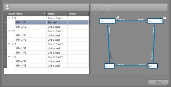
2. PHYSICAL LINKS: CONNECT ALL NODES INTO A WAN NETWORK
2.1 General

CAUTION: Maximum 255 nodes in series, maximum 255 hops;

    Optical WAN links can be created on (see WAN support in feature matrix §12):
       4-GC-LW/4-GCB-LW IFM (=interface module) → 1 Gbps, one link per module;
       4-GO-LW IFM → 1 Gbps, four links per module;
       1-10G-LW IFM → 10 Gbps, one link per module;
       4-10G-LW IFM → 10 Gbps, four links per module;
       1-40G-LW IFM → 40 Gbps, one link per module;
    Electrical WAN links can be created on:
       a 4-GC-LW/4-GCB-LW IFM:
            Four links per module if no optical link (port1) is coming up on this module;
            Three links per module if an optical link (port1) is coming up on this module.
Connect all the links in all the nodes as described in the paragraphs below. Once the entire
WAN network has been connected, ports not used as WAN port can be used as LAN port.
The RJ45 port of combo port1 can only be used when there is no optical link on this port.

2.2 Connect Optical Link via Fiber/SFP/XFP/QSFP+

CAUTION:
Make sure that the used TRMs (=SFPs/XFPs/QSFPs+) are suited for the optical link
distance. A received optical budget that exceeds the TRM receiver sensitivity level (or the
transmitting TRM is too powerful for the link distance), could damage the receiving TRM.
More information on the TRMs can be found in Ref.[14] in Table 1.

    Plug in TRM module:
       SFP module into the SFP connector (=port1) of a 4-GC-LW/4-GCB-LW/
       4-GO-LW IFM;
       XFP module into the XFP connector of a 1-10G-LW/4-10G-LW IFM;
       QSFP+ module into the QSFP+ connector of a 1-40G-LW IFM;
    Plug in the optical fiber into the SFP/XFP/QSFP+ module;
NOTE: Smart SFP (see Ref. [2Leg] in Table 1) cannot be used to interconnect Dragon PTN
      nodes;

NOTE: Fiber optic reporting information is available via the Reporting Engine Add-on, see
      see Ref. [24] in Table 1.

2.3 Connect Electrical Link via Copper/RJ45
    Plug in the copper cable into an available RJ45 port of a 4-GC-LW IFM/4-GCB-LW;
    When using the RJ45 connector from combo port1 on the 4-GC-LW/4-GCB-LW IFM, make
    sure that no optical link will come up on the SFP of that combo port. Within a combo port,
    an upcoming optical link will always have priority over the electrical copper link, and as a
    result will disable the electrical port;

8                                                                 Dragon PTN Network Operation
                                                                               Release 01 05/2020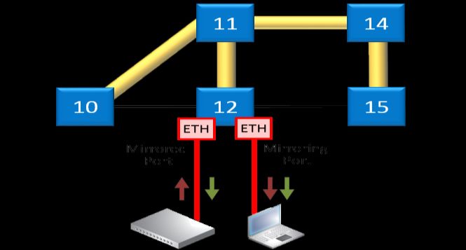
3. HIPROVISION: DISCOVER NETWORK, DEPLOY DCN, CREATE LINKS
3.1 General
The Dragon PTN network can be discovered via connecting the HiProvision PC to the Dragon
PTN network, and start the Discovery function. The discovered network will be visualised in
HiProvision and the discovered links can be created automatically after the discovery phase.
More info on discovery and link creation in ref. [2Mgt] in Table 1.

3.2 DCN Channel
The DCN (=Data Communication Network) Channel is the Dragon PTN network management
channel which is deployed dynamically over each link of the entire network during the
discovery phase, see Ref. [2Mgt] in Table 1. HiProvision uses this channel to communicate
with the entire Dragon PTN network.

3.3 DCN Bandwidth Profile
The bandwidth of the DCN channel can be configured per individual 1G/10G/40G Ethernet
link, making part of the DCN channel, via Dashboard → Network Hardware → Links → Link
→ Generic: DCN Bandwidth Profile:

    40 Mbps (=default): Use this value if you have plenty of bandwidth available in your
    network. All your management activities will go fast/normal;
    20 Mbps;
    5 Mbps;
    1.5 Mbps: Use this value if you have to consume your bandwidth very efficiently or if you
    have lack of bandwidth in your network. Your management activities could go slow/slower
    depending on the network layout and load;
NOTE: The selected bandwidth also influences the number of protected tunnels through
      this link, see paragraph below.

NOTE: Management activity example: Load firmware into the network, see Ref. [2Mgt] in
      Table 1.

NOTE: The DCN Bandwidth Profile must always be less than the Link Capacity (see §3.4).

This configured bandwidth is automatically reserved during discovery.

                                                            Link Capacity

 Link

                                                                        DCN Bandwidth Profile

                            Figure 2 Link: DCN Bandwidth Profile

Dragon PTN Network Operation                                                                    9
Release 01 05/2020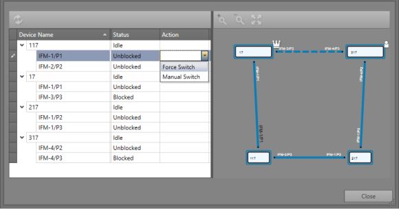
3.4 Link Capacity
The link capacity of the Ethernet link is the maximum data rate through a link cable. This
value equals by default the port speed of the port in which the cable is plugged in. E.g. if a
link cable is plugged in into a 1000 Mbps port, the Link Capacity is by default 1000 Mbps.

The Link Capacity can be configured or downscaled if desired via Dashboard → Network
Hardware → Links → Link → Generic: Link Capacity (L1):

       Ethernet 1G: default = 1000 Mbps, Range [10...1000] Mbps;
       Ethernet 10G: default = 9294 Mbps, Range [10...10000] Mbps;
       Ethernet 40G: default = 40000 Mbps, Range [10...40000] Mbps;

NOTE: The Link Capacity must always be more than the DCN Bandwidth Profile (see §3.3);

                                                            Link Capacity

Link

                                                                            DCN Bandwidth Profile

                              Figure 3 Ethernet Link: Link Capacity

3.5 Amount of Protected Tunnels
The number of logical ring, point-to-point/multipoint with protection and subring tunnels
that can be configured through a link depends on the selected DCN Bandwidth profile for
that link.

       40 Mbps (=default): Maximum 128 protected tunnels possible;
       20 Mbps: Maximum 64 protected tunnels possible;
       5 Mbps: Maximum 8 protected tunnels possible;
       1.5 Mbps: Maximum 2 protected tunnels possible;

4. HIPROVISION: SET THE LAN PORTS IN YOUR NETWORK
WAN ports interconnect nodes within the Dragon PTN network (MPLS-TP) whereas LAN
ports interconnect the nodes with their applications.

By default, all the ports of the IFMs that support WAN ports (see §12) are WAN ports. This is
because nodes are discovered via the HiProvision discovery function, which operates over
MPLS-TP links that interconnect nodes via WAN ports. Ports that do not have a WAN link can
be changed into a LAN port by using the network settings wizard.

The network settings wizard allows to easily set all the port configurations of multiple IFMs
together, without having to open each IFM individually. Click the Network Settings Wizard
button       (see previous paragraph) to open it.

10                                                                    Dragon PTN Network Operation
                                                                                          Release 01 05/2020
The list below summarizes every page in the wizard:
Information: Click Next>>;
Selection: select Port Mode;
Port Mode Settings: By default, all the ports of the IFMs that support WAN ports (see §12)
are WAN ports. The ports with a connected WAN link, are indicated by . These
ports cannot be adapted anymore in this wizard. If all the other ports must be set to LAN,
click the button. If not, set the ports individually to LAN or WAN via the LAN/WAN drop-
down selectors. See figure below.
Review: If ok, click Finish. The configuration load manager will be invoked.
Load: The configuration load manager is a tool that starts and monitors the load process
of a HiProvision configuration. Click the Load button to load the new HiProvision
configuration into the live network. See Ref. [2Mgt] in Table 1 for more info;
CAUTION: While the loading to the Dragon PTN network is in progress, do not turn off,
shut down or restart the HiProvision Server or Agent, since this may cause database
corruption and network problems!
LAN/WAN
drop-down list
Figure 4 LAN/WAN Settings
5. HIPROVISION: CREATE MPLS-TP TUNNEL(S)
Prerequisite: all the necessary nodes and interface modules are configured in the database.
5.1 General
A tunnel is a virtual path through the physical network in which customer application
services can be programmed later on. The concept of a tunnel can be found in the figure
below. A network consists of nodes with links in between. The bandwidth within a link is
divided over the configured tunnels through that link. The tunnels can start or end in a node
(=LER) or just pass through a node (=LSR) and will be used to program customer application
services in.
LER: Label Edge Router = MPLS-TP access node with customer applications;
Dragon PTN Network Operation 11
Release 01 05/2020LSR: Label Switching Router = MPLS-TP transfer node. A programmed service can have no
end-points in an LSR node;
Figure 5 Tunnel Creation
In HiProvision, it is possible to create tunnels in a predefined topology, with or without a
protection path. See the table and figures below for an overview:
Table 2 Tunnel Topologies and Protection
Tunnel Topology Protection
Point-to-point Optional
Multipoint Optional
Logical Ring Always, included automatically via RPL (=Ring Protection Link)
(max. 60 LERs per tunnel)
Subring Always, included automatically via RPL
(max. 15 Subrings per Logical Ring
External (*) None
(*) Note: An 'External' tunnel type cannot be selected or created manually. Such a tunnel will be created
automatically when creating an 'External E1 Link'. 'External E1 Links' must only be used when the Local Mode
service is used on 2-OLS or 2-C37.94 IFMs, see Ref. [2Leg] in Table 1.
This external tunnel cannot be modified/deleted. It will be deleted automatically when deleting the associated
'External E1 Link'.
A tunnel with protection consists of a working and a protection path:
Working path (yellow in the figures below): the active data path;
Protection path (orange in the figures below): the standby or backup data path if the
working path should fail. This path is optional for point-to-point and multi-point tunnels
and mandatory for logical ring or subring tunnels. Switching between the working path and
protection path occurs automatically due to a working path failure or can be initiated
manually for maintenance reasons for example, see §5.7.
The possible amount of protected tunnels through a link depends on the selected DCN
bandwidth profile for that link, see §3.3.
12 Dragon PTN Network Operation
Release 01 05/2020Point-to-Point Point-to-Point
no protection with protection
11 14 11 14
Working Path Working Path
10 12 15 16 10 12 15 16
13 13 Protection Path
Figure 6 Point-to-Point Tunnels
MultiPoint MultiPoint
no protection with protection
11 14 11 14
10 12 15 16 10 12 15 16
Protection
13 13
Protection
Figure 7 MultiPoint Tunnels
Logical Ring
with protection
11 14
10 12 15 16
Owner
13
Protection = RPL =
Ring Protection Link Neighbor
Figure 8 Logical Ring Tunnel
Dragon PTN Network Operation 13
Release 01 05/2020Logical Ring
with protection
11 14
Logical Ring (LR)
10 12 15 16
Neighbor (LR)
Subring
13 Subring (S)
with protection
Protection = RPL (LR)
Owner (LR) 17 18
Owner (S) Protection = RPL (S) Neighbor (S)
Figure 9 Subring Tunnel
5.2 Tunnel Creation
NOTE: If needed, a tunnel can be modified later on as described in §5.4.
NOTE: If you want to create a Subring tunnel, read §5.3 first.
Click Dashboard → Configuration → Connections → Tunnels → to open the tunnels
wizard. See figure below.
Connections Tab
Create Tunnels
Tunnels
Figure 10 Create Tunnels
The tunnels wizard opens. The list below summarizes every page in the wizard. :
Information: Click Next>>;
Topology Selection: enter a tunnel name, select a topology (see also §5.1) with optional
protection;
Ring Tunnel Selection (only when SubRing topology was selected): a 'Logical Ring' must be
chosen to configure subrings on. Select a Logical Ring in the Tunnels list.
Device Selection:
14 Dragon PTN Network Operation
Release 01 05/2020Select the nodes to which your customer applications for this tunnel will be connected
later on. Only select LERs, no LSRs. For Subrings: Select all the devices or nodes of the
subring including the interconnection nodes on the Logical Ring. A logical ring can have
a maximum of 60 LERs.
Subring Interconnection nodes: see §5.3;
A node can be selected by clicking the node icon or its ‘Selected’ checkbox. A selected
node icon is colored turquoise, an unselected node icon is colored white. A node can
be unselected by clicking again on the node icon or its ‘Selected’ checkbox. Make sure
that your node selection makes sense for the selected topology. Multiple nodes can be
selected/unselected at once via selecting a number of rows and clicking / .
Devices
Click device
to add to tunnel
Click device
to add to tunnel
Figure 11 Tunnel - Device Selection
Link Selection: Select the links that must be part of the tunnel. A link can be selected by
clicking the link line between the node icons or by clicking the ‘Selected’ checkbox. A
selected link is colored brown, an unselected link is colored grey. Click again on this link or
its ‘Selected’ checkbox to unselect the link. Multiple links can be selected/unselected at
once via selecting a number of rows and clicking / .
Click link
to add to tunnel
Links
Figure 12 Tunnel - Link Selection
Protection Setup (optional, if protection was selected in the Topology Selection):
Dragon PTN Network Operation 15
Release 01 05/2020Point-to-point: Just select the links of the protection path to configure the protection
path (link selection/unselection is similar as described above).
Multipoint: at least one of the different working paths within the Multipoint tunnel
must be protected. For each working path (or LSP) that is going to be protected:
Set the Protection Mode to 1:1, see figure below. The working path in the network
drawing is blue, so that you know which path is going to be protected.
Figure 13 Set Protection Mode of LSP
Next select all the links of the protection path (link selection/unselection is similar
as described above). After this, the protection path is configured.
Logical Ring: See next paragraph.
QoS Parameters: HQoS (= is way to prioritize service traffic via assigning a priority to the
tunnel in which the service data is transported.
Use HQoS/HQoS Application Priority (HQoS = Hierarchical Quality of Service):
Unchecked (=default): No HQoS will be used.
Checked: An HQoS Application Priority (0 = default = lowest priority, …., 6 = highest
priority) can be assigned to the tunnel if Use HQoS has been checked. More info
on HQoS can be found in Ref. [2Eth] in Table 1. Click Next >>.
Figure 14 Tunnel HQoS / HQoS Application Priority
Protection Parameters :
16 Dragon PTN Network Operation
Release 01 05/2020Only visible for Tunnel Topology = Subring
Figure 15 Protection Parameters
Use Shared LSP (for Logical Ring and Subring tunnels):
checked (=default): Allows to reuse existing tunnel resources resulting in more
performant and faster switchover times. Switchover from the working path to the
protection path occurs when the normal working path gets broken.
unchecked: This tunnel will not reuse other tunnel resources and as a result, the
switchover behavior becomes less performant.
Ring Priority (default = 127, range[0-255]) (for Logical Ring and Subring tunnels): This
field is only for tunnels using LSP sharing ('Use Shared LSP' = checked). It decides the
switchover order when multiple shared rings have to switchover simultaneously due
to a link break or recovery. The ring with the lowest ring priority value will switchover
first. If some of these rings have the same priority, the ring that was created first will
switchover first.
Revertive/Wait to Restore time (=WTR) (default=1 minute, range[1..12] minutes):
Revertive = checked: Initial active path A (=working path) is the preferred path. If
this path fails, it will become the active path again after it restores and being stable
for at least a period indicated by the ‘Wait to Restore Time’. In between, the
redundant path B (=protection path) will be the active path;
Revertive = unchecked: If the initial active path A (=working path) fails, redundant
path B (=protection path) becomes active and remains active even when path A
repairs later on;
BFD interval (default = 5ms, range[3-500]ms). Indicates the Bidirectional Forwarding
Detection interval between BFD packets. BFD is used to detect the link status (e.g. is
the link still up or down?). BFD packets are used in protected tunnels except in hitless
switching tunnels. Monitored BFD information and protection info can be found in the
Network tile. Select the desired tunnel and show its properties via the button;
Dragon PTN Network Operation 17
Release 01 05/2020Owner / Neighbor Device (only for Logical Ring and Subring): The Ring protection path
is a link between two adjacent end nodes or LERs. This protection path is called the RPL
or Ring Protection Link. These two end nodes are called the owner and the neighbor of
the RPL. Only when the working path is broken this RPL will be activated.
Owner: is the owner or master controller of the RPL. Select the owner device in the
Owner Device list by clicking the Selected checkbox;
Neighbor: is the neighbor or slave of the RPL, it listens to control packets of the
owner, and as a result opens/closes its RPL port to open/close the RPL. If the
working path is OK, this port is closed. Select the neighbor device in the Neighbor
Device list by clicking the Selected checkbox. Only adjacent LER (=Label Edge
Router) nodes of the owner node are selectable.
Propagate Topology Change ( = PTC = only for Subrings): Topology change propagation
is a process that informs the network about path breaks (physical/logical) in one of its
subrings. As a result, all the subrings between the broken subring up to the main ring
will be able to flush their nodes. Flushing a node clears the learned MAC addresses to
initiate new path recalculations to the broken subring. When the broken subring is
connected to the main ring via a more complex network structure (e.g. sideway subring
structures), the propagation always follows the shortest path towards the main ring.
Checked (=default): This subring communicates its own ring breaks (or topology
changes) and also forwards incoming topology change notifications from other
subrings.
Example (see figure below): LR = Logical Ring = Main Ring, S(n) = Subring(n). This
subring = S2 and connected to other rings as follows: LR → S1 → S2 → S3;
If a path ring break occurs in this S2, a topology change will be communicated
to S1 (= towards the main ring) but not to S3 (=away from the main ring);
Incoming topology changes in S2 from a lower S3, if any, will be forwarded to
the higher S1;
After the subring tunnel creation, a ‘Topology Change Propagation’ tab can be
viewed in the Connections Tile when selecting the subring in the TUNNELS list.
It shows the RING IDs of the ring/subring that will be flushed by the PTC of this
subring. The RING IDs of each ring/subring can be found in the ‘Ring Protection’
tab, see figures below.
Unchecked: This subring will not communicate its own ring breaks (or topology
changes) nor forward incoming topology changes from other subrings.
18 Dragon PTN Network Operation
Release 01 05/2020= Logical Break; = Physical Break
Main Ring with Cable break in = PTC flushed node
3 subrings subring S2 = Own flushed node
Main Ring
LR LR LR flushed
S1 S1 S1 PTC = ON
S2 S2 S2 PTC = ON
S3 S3 S3
Figure 16 Example: Propagate Topology Change (=PTC)
RingX
(Ring ID=4)
SubRingX1
(Ring ID=5)
SubRingX2
(Ring ID=7)
Figure 17 Example: Main Ring + Subrings
Dragon PTN Network Operation 19
Release 01 05/2020RingX
(Ring ID=4)
Figure 18 RingX (=Main Ring): Ring Protection Tab
SubRingX1
(Ring ID=5)
SubRingX1
flushes
Main Ring (=ID4) → First interconnection node → Second interconnection node
to the upper ring/subring to the upper ring/subring
→ Ring ID of the upper ring/subring → Ring ID of the upper ring/subring
that will be flushed. that will be flushed.
Figure 19 SubringX1: Ring Protection / Topology Change Propagation Tab
SubRingX2
(Ring ID=7)
SubRingX2
flushes
SubRingX1 (=ID5)
Figure 20 SubringX2: Ring Protection / Topology Change Propagation Tab
20 Dragon PTN Network Operation
Release 01 05/2020LSP Label Selection: This page depends on the selected tunnel topology and the 'Use
Shared LSP' (only for Logical Ring/Subring) setting from the previous wizard page.
Point-to-Point/Multipoint: LSP Sharing not relevant;
Logical Ring/Subring: reusing resources is more performant than not reusing resources,
especially when multiple tunnels go over the same link. Reusing resources = reusing
existing LSP labels from existing tunnels. Per link between two nodes, you can decide
whether to share your new tunnel with other existing tunnels. This can be done via
clicking the appropriate radio buttons or selecting the desired tunnel(s) to share with
via the tunnel/link drop-down lists. By default, sharing is activated per link if any other
tunnel is already available in this link. Sometimes, sharing is not possible, see Figure 22.
- Point-to-Point
- Multipoint Sharing not relevant
- Logical Ring
- Subring
(Advised)
Use Shared LSP
→ Performant
Reuse (share) of
resources
Non-shared LSP No reuse of
→ Less performant resources
Figure 21 Share LSP: Shared/Non-Shared LSPs
Dragon PTN Network Operation 21
Release 01 05/2020LSP sharing possible LSP sharing not possible
(Same LERs for both LSPs) (One node is LER and LSR)
LSP1 LSP1
LER for LSR for LSP1 (no red
both LSPs bullet)
LER for LSP2
LSP2 LSP2
Figure 22 LSP Sharing Possible?
Review: If ok, click Finish. The configuration load manager will be invoked.
Load: The configuration load manager is a tool that starts and monitors the load process
of a HiProvision configuration. Click the Load button to load the new HiProvision
configuration into the live network. See Ref. [2Mgt] in Table 1 for more info.
CAUTION: While the loading to the Dragon PTN network is in progress, do not turn off,
shut down or restart the HiProvision Server or Agent, since this may cause database
corruption and network problems!
5.3 Subrings
5.3.1 General
A 'Logical Ring' tunnel can have a maximum of 60 LERs. It can be easily extended by
connecting subrings (or 'Subring' tunnels) to it via two interconnection nodes which
terminate the subring. Each subring has its own RPL (=ring protection link). The resulting
network combining Logical Ring and one or more subrings is called a ladder topology. See
figure below.
NOTE: The number of subrings through a link depends on the selected DCN bandwidth
profile for that link, see §3.5.
Ladder Topology
LR = Logical Ring
RPL
LR LR LR
Interconnection
Interconnection
Node S1 Node S1 S1
RPL
S = Subring
Figure 1 Logical Ring / Interconnection Nodes / Subring / Ladder Topology
22 Dragon PTN Network Operation
Release 01 05/2020step 0: step 1: step 2:
meshed nodes create tunnel: create tunnel:
‘Logical Ring’ LR ‘Subring’ S1
LR LR
Interconnection Interconnection
Node Node
S1
LR = Logical Ring S = Subring
Figure 2 Logical Ring / Subring Setup
A Subring:
is a tunnel topology type;
is a tunnel extension of a 'Logical Ring' tunnel;
must be connected via 2 interconnection nodes to a Logical Ring or the existing ladder
topology;
is terminated on the interconnection nodes;
can be connected to maximum one logical ring;
contains at least 3 nodes;
has its own RPL;
should not share a link with the ladder topology;
Different configured Subrings in the same logical ring have another Subring color:
Figure 3 Subring Colors
A Logical Ring:
can nest subrings maximum 3 levels deep (Logical Ring not included);
can have maximum 15 subrings connected, either directly or indirectly via other subrings
or a mix;
An interconnection node:
is a node in the ladder topology to which one side of a subring is connected;
is always a LER node;
can be (re)used or shared by multiple subrings;
Hint: Do not share a link with the ladder topology when configuring a subring.
Dragon PTN Network Operation 23
Release 01 05/20205.3.2 Ladder Topology Examples
The figures below show example configurations with subrings. LR = logical ring; S = Subring.
Maximum 3 subring Maximum 15 subrings Shared interconnection nodes
levels deep
LR Sn LR S15 LR
S1 S1
S1 S4
S2 S2
S3 S3 S2 S5
S3
Figure 4 Ladder Topology Example 1
S4/S5 connected to S5 connected to
logical ring and subring multiple subrings
S5 LR S4 LR S4
S1 S1 S5
S2 S2
S3 S3
Figure 5 Ladder Topology Example 2
Allowed Shared Link → Not Allowed
LR S1 LR S1
Shared Link
Figure 6 Ladder Topology: Not Allowed: Shared Link
24 Dragon PTN Network Operation
Release 01 05/2020Allowed Only 2 nodes → Not Allowed
Not allowed subring with
LR LR only 2 nodes
Figure 7 Ladder Topology: Not Allowed: Only 2 Nodes in Subring
5.3.3 Protected Tunnels
The working path and protection path in a protected tunnel are visualized in §5.5.
5.4 Tunnel Modification
Click Dashboard → Configuration → Connections → Tunnels → select tunnel → to
modify the tunnel. The following properties can be modified:
Tunnel Name, Ring Priority (if LSP sharing is used);
For Ring tunnels: Use HQoS, HQoS Application Priority.
5.5 Monitor Protected Tunnel
The working and protection path in a protected tunnel are visualized in the figure below.
This view is visible when selecting a tunnel or tunnel layer in the (Monitoring) Network Tab.
‘//’ indicates a blocked
link port on the node
1) Normal working 2) White ‘//’: 3) Orange ‘//’ : Normal working
path = OK protection path = standby 4) protection path = active
path = NOK or broken
Normal
working path
breaks
Figure 8 Protected Tunnels: Protection Path, Blocked Port Indication: '//'
Dragon PTN Network Operation 25
Release 01 05/20205.6 Reporting
Tunnel Reporting information is available via the Reporting Engine Add-on, see Ref.[24] in
Table 1.
5.7 Tunnel Actions: Swap Working Path ←→ Protection Path
5.7.1 General
In a tunnel, it is possible to swap manually from the working to the protection path (=backup
path) or vice versa. This is very handy for testing purposes or for link maintenance activities.
NOTE: Swapping paths can also be done the hardware way by just pulling out a link or
cable when the protection switching is operational.
1. Go to Dashboard → (Monitoring) Network Tile → TUNNELS Tab;
2. Select a protected tunnel in the Tunnels list to highlight the tunnel action button ;
3. Click the tunnel action button ;
TUNNELS Tab
2) Click Action Button
1) Select Protected Tunnel
Figure 9 Protected Tunnel/Actions
4. The 'Action on Tunnel' window shows up and depends on the selected tunnel type:
Point-to-Point/Multipoint Tunnels: see §5.7.2;
Ring/Subring Tunnels: see §5.7.3;
5.7.2 Point-to-Point/Multipoint Tunnels
The 'Action on Tunnel' window looks as in the figure below.
NOTE: Click 'Working Path' or 'Protection Path' to highlight it in the network drawing.
26 Dragon PTN Network Operation
Release 01 05/2020Nodes Actions → no 1) Select Node 2) Select Action
action yet
Working path active No tunnel
actions running
Status in Network Tile:
Refresh button After switch: Working
Protection
path
path
active
active
Tunnel selected → LPS → Status
Figure 10 Point-to-Point/Multipoint Action on Tunnel Window
1. Select the node in the Send to Node list that must trigger the swap from working to
protection path. For a point-to-point tunnel, either node is OK;
2. Select a '...Switch To...' command in the Action on LSP list, see Table 3 for a command
overview. Click OK in the pop-up box to execute the command in the live network!
3. Some status info will change (Node:///, working path, protection path). For
more detailed tunnel status information, click Close. Go to the Network tile → Select
tunnel. Status info is shown in the Network drawing or properties tabs via , e.g. LPS tab
(=Linear Protection Switching). Click the Refresh button for faster feedback. Also have a
look at §5.5.
4. If the swap is OK ('protection path active'), perform the required maintenance (if any);
5. If you are ready to swap back to the working path and you closed the Tunnel actions
window, open it again via .
6. Swap back to the working path by selecting the Clear command in the Action on LSP list.
Use 'Clear' only on the node where the '...Switch To...' command was executed! Click OK
in the pop-up box to execute it! If the swap back does not occur immediately, probably a
Wait to Restore timer has to expire first. The Wait to Restore time has been configured at
the tunnel creation.
CAUTION: Use 'Clear' only on the node where the '...Switch To...' command was executed!
5.7.3 Ring/Subring Tunnels
The 'Action on Tunnel' window looks as in the figure below.
NOTE: An 'Idle' ring indicates an up and running ring, the working path (=full line) is active
and the protection path (=dashed line) is in standby.
Dragon PTN Network Operation 27
Release 01 05/2020Ring Status Tunnel Actions Ring after a ‘forced switch’, 1 port blocked
Protection Path
Working Path Blocked
Status in Network Tile:
Tunnel selected → Ring Protection Refresh button Port on which a ‘Force
Switch’ was executed
Figure 11 Ring/SubRing Action on Tunnel Window
1. Decide which node must trigger, by blocking a port, a swap from working to protection
path. For the port that must be blocked, select a port '...Switch' action. See Table 3 for a
command overview. Click OK in the pop-up box to execute it in the live network!
2. Both the Node and Port status will change. For more detailed tunnel status information,
click Close. Go to the Network tile → Select tunnel. Status info is shown in the Network
drawing or properties tabs via , e.g. Ring Protection tab. Click the Refresh button for
faster feedback. Also have a look at §5.5.
3. If the swap is OK (Ring State is Forced Switch/Manual Switch and one port is blocked),
perform the required maintenance (if any);
4. If you are ready to swap back to the working path and you closed the Tunnel actions
window, open it again via .
5. Swap back to the working path by selecting the Clear command in the Node Action list of
the node where the '...Switch' command was executed (see figure below). It is the node
that has one port in the 'Blocked' state. Click OK in the pop-up box to execute the
command! If the swap does not occur immediately, probably a Wait to Restore timer has
to expire first. The Wait to Restore time has been configured at tunnel creation.
Port on which the ‘Force Switch’
command was initiated
Figure 12 Clear Command in the Node Action List
CAUTION: Use 'Clear' only on the node where the '...Switch' command was executed!
28 Dragon PTN Network Operation
Release 01 05/20205.7.4 Tunnel Action Commands
Table 3 Tunnel Action Commands
Tunnel Type Level Command Description
Point-to-Point / Node Clear Swaps the tunnel back to the working path if this path is OK. Use this
Multipoint command only on the node where a Force/ Manual Switch to Protection
command has been performed. If the swap back does not occur
immediately, probably a Wait to restore timer has to expire first.
Force Switch to - Swaps the tunnel in a forced way to the protection path, also if the
Protection protection path is not OK! Attention: if both the working and
protection path are not OK, communication will be lost between the
two end-points;
- After the swap, if the protection path breaks, there will be no
automatic swap to the working path.
Manual Switch to - Swaps the tunnel to the protection path if all tunnel paths are ok, no
Protection error conditions!
- After the swap, if the protection path breaks, the tunnel swaps back to
the working path automatically if the tunnel was configured as
revertive.
Manual Switch to - Swaps the tunnel to the working path only if the working path is OK!
Working This is useful when your tunnel has swapped to the protection path
automatically due to a real break (not via tunnel actions) and your
tunnel is non-revertive;
- This command has the same effect as the Clear command.
Ring / SubRing Node Clear Same as 'Clear' command described above.
Port Force Switch Same as 'Force Switch to Protection' command described above.
Manual Switch Same as 'Manual Switch to Protection' command described above.
6. CSM REDUNDANCY
Prerequisite: one CSM Redundancy voucher (see Ref. [2Mgt] in Table 1) or license is required
for each node having two CSMs installed.
A node can have two CSMs installed for redundancy reasons. A CSM can be in the Active,
Standby or Passive state. Normally, one CSM will be Active and the other will be Standby.
NOTE: More info on CSM Redundancy can be found in Ref.[2Mgt], [4] in Table 1 and in the
redundancy cases in in Ref.[2Mgt];
CAUTION: Both CSMs must be connected with a management cable!
1. Both CSMs can be viewed via Dashboard → Network Hardware;
2. Select the node row in the list and expand it, the two CSMs will be visible if configured and
the CSM switchover button becomes active;
Dragon PTN Network Operation 29
Release 01 05/2020CSM switchover
Node selected
Standby
Active
Active
Figure 13 Node with 2 CSMs, CSM Switchover Button
3. The Active CSM is indicated with a little square (◼).
4. The Redundancy State can be viewed in the Redundancy section after selecting a CSM:
Active CSM (◼) selected
Standby CSM selected
Figure 14 CSM Redundancy Status
5. With CSM redundancy, a switchover is only possible when both CSMs have the same
firmware version and one CSM is 'active' and the other CSM is 'standby'.
6. To manually switchover the CSMs or make the Standby CSM the active one and vice versa,
select the node row and click the CSM switchover button . More switchover
possibilities are described Ref. [4];
7. CSM Redundancy is non-revertive.
7. SYNCE
7.1 General
SyncE is a protocol that manages the distribution of a synchronous clock, based on a PRC
(=Primary Reference Clock), network wide over all the nodes that have SyncE configured.
The protocol uses SSMs (= Synchronization Status Message) to inform the nodes about the
quality of the clock on that link. The clock itself is recovered from the received electrical/
optical signals on the configured recovery ports (see also Ref. [4] in Table 1). Recovery ports
can be configured on the IFMs that support the SyncE feature, see §12.
Some facts:
30 Dragon PTN Network Operation
Release 01 05/2020Maximum one SyncE recovery port per IFM;
Maximum four SyncE recovery ports per Node;
SyncE is non-revertive for clocks with the same quality and priority (see also §7.3).
All physical port interfaces from the IFMs listed above, support a unidirectional
synchronization (=default). E.g. port y on Node2 recovers a clock from port x on Node1.
Some interfaces support a bidirectional synchronization as well, e.g. Node2 is able to recover
a clock from Node1 and vice versa on the same link. But in operation, the clock will only be
recovered in one direction at the same time.
A bidirectional link is possible when both requirements below are met:
both ports on the link are configured as recovery port;
the physical interface matches one of the interfaces below:
Optical Ethernet (IFM 4-GC-LW/4-GCB-LW, 4-GO-LW, 1-10G-LW, 4-10G-LW, 1-40G-
LW);
Optical C37.94 (IFM 2-C37.94);
Electrical Ethernet 100 Mpbs (IFM 4-GC-LW/4-GCB-LW).
= SyncE SSM = SyncE recovery port
PRC Unidirectional PRC Bidirectional
PRC, PRC, DUS,
Prio2 Prio2 Prio2
Figure 15 Unidirectional/Bidirectional SyncE Examples
Make sure not to configure timing loops when configuring SyncE. In a timing loop, when the
master PRC node breaks down, the other nodes start synchronizing on each other, still
believing the master PRC is up and running. As a result, the nodes in the timing loop slowly
drift away from the rest of the network, and they possibly never pick up again with the PRC
master whenever it comes back because of the non-revertive behavior (see §7.3).
Make sure to build in synchronization redundancy but be aware of timing loops!
Dragon PTN Network Operation 31
Release 01 05/2020You can also read