User Manual WLAN Outdoor Guide - WLAN Outdoor Guide Technical support - Hirschmann ...
←
→
Page content transcription
If your browser does not render page correctly, please read the page content below
User Manual
WLAN Outdoor Guide

WLAN Outdoor Guide                 Technical support
Release 03 08/2020   https://hirschmann-support.belden.com
The naming of copyrighted trademarks in this manual, even when not specially indicated, should
not be taken to mean that these names may be considered as free in the sense of the trademark
and tradename protection law and hence that they may be freely used by anyone.

© 2020 Hirschmann Automation and Control GmbH

Manuals and software are protected by copyright. All rights reserved. The copying, reproduction,
translation, conversion into any electronic medium or machine scannable form is not permitted,
either in whole or in part. An exception is the preparation of a backup copy of the software for
your own use.

The performance features described here are binding only if they have been expressly agreed
when the contract was made. This document was produced by Hirschmann Automation and
Control GmbH according to the best of the company's knowledge. Hirschmann reserves the right
to change the contents of this document without prior notice. Hirschmann can give no guarantee
in respect of the correctness or accuracy of the information in this document.

Hirschmann can accept no responsibility for damages, resulting from the use of the network
components or the associated operating software. In addition, we refer to the conditions of use
specified in the license contract.

You can get the latest version of this manual on the Internet at the Hirschmann product site
(www.hirschmann.com).

Hirschmann Automation and Control GmbH
Stuttgarter Str. 45-51
72654 Neckartenzlingen
Germany

                                                                          WLAN Outdoor Guide
10.08.2020                                                                      Release 03 08/2020
Contents
Contents
Safety instructions 5
About this manual 7
1 Introduction 9
1.1 Device Roles 10
1.1.1 Access Point 11
1.1.2 WLAN Bridge (point-to-point) 12
1.1.3 WLAN Bridge Relay 13
1.1.4 WLAN Distribution Point - (Point-to-Multipoint) 14
1.1.5 WLAN Client 15
1.1.6 WLAN Roaming Clients 16
1.2 Components of the WLAN system 17
1.2.1 Access Points 17
1.2.2 Power supply to the Access Points 18
1.2.3 External antennas 18
1.2.4 Components for lightning protection and surge
protection 19
1.3 Selecting the frequency band 20
1.3.1 2.4 GHz band or 5 GHz band 20
1.3.2 Special regulations for the 5 GHz band 21
2 Setting up P2P connections 27
2.1 The Antenna Calculator 29
2.1.1 Data throughput: Nominal vs. Actual 29
2.2 Geometric dimensioning of P2P links 30
2.3 Antenna alignment 34
2.4 Measuring wireless bridges 38
3 Lightning protection and surge protection 39
3.1 Formation of lightning discharges 40
3.2 External lightning protection 43
WLAN Outdoor Guide
Release 03 08/2020 3Contents
3.3 Internal lightning protection 44
3.4 Selecting the components for lightning protection and surge
protection 47
3.4.1 Classification of surge protective devices 47
3.4.2 External lightning protection 48
3.4.3 Internal lightning protection 49
3.4.4 Example applications 50
4 Installation 57
4.1 Mounting Notes 58
4.2 Mounting the Access Points 60
4.2.1 Selecting the location for mounting 61
4.2.2 Installing the device onto or on a flat surface 61
4.2.3 Installing the device on a pole 62
4.3 Mounting antennas 63
4.3.1 Selecting the location for mounting 64
4.3.2 Flat surface mounting 65
4.3.3 Pole mounting 66
4.4 Mounting the lightning rods 67
4.4.1 Dimensioning of the lightning rod 68
4.4.2 Distance to the components at risk 68
4.4.3 Lightning charge conduction (grounding) 70
A Appendix 71
A.1 Antenna characteristics 72
A.2 Troubleshooting 73
B Further support 75
WLAN Outdoor Guide
4 Release 03 08/2020Safety instructions
Safety instructions
Notes on safety
This manual contains instructions to be observed for ensuring your
personal safety and for preventing damage. The warnings appear next to
a warning triangle with a different heading depending on the degree of
danger posed:
Danger!
Means that death, serious physical injury or significant damage
to property will occur if the corresponding safety measures are
not carried out.
Warning!
Means that death, serious physical injury or significant damage
to property could occur if the corresponding safety measures
are not carried out.
Caution!
Means that minor physical injury or damage to property can
occur if the required safety measures are not carried out.
Note: Contains important information on the product, on how to manage
the product, or on the respective section of the documentation to which
your special attention is being drawn.
WLAN Outdoor Guide
Release 03 08/2020 5Safety instructions
WLAN Outdoor Guide
6 Release 03 08/2020About this manual About this manual The advantages of wireless LANs (WLANs) are obvious – they offer flexibility, mobility and convenience at a lower cost than cabled networks. WLANs can be quickly installed without any changes to the construction of the building, and they offer new applications not available with cabled LANs. Access Points in combination with suitable antennas are ideal for setting up WLANs, either indoors or outdoors. This document applies for all BAT Access Points in combination with appropriate antennas and it provides general information on the outdoor operation of wireless LAN systems. Information on the installation and basic configuration of the various Access Points and antennas is available from the corresponding installation manual. Note: Protecting the components employed from the consequences of lightning strikes and other electrostatic influences is one of the most important aspects to be considered when designing and installing wireless LAN systems for outdoor use. Please refer to the appropriate notes (see on page 39 “Lightning protection and surge protection”) as otherwise Hirschmann cannot provide any guarantee for damage to the components. Note: Safety notices concerning the mounting and installation of WLAN system components are to be found at relevant locations in the following chapters. WLAN Outdoor Guide Release 03 08/2020 7
About this manual

                    WLAN Outdoor Guide
8                       Release 03 08/2020
Introduction 1 Introduction This chapter presents the basic scenarios for wireless local area network (WLAN) outdoor systems. It also lists the type of components required to set up a WLAN system outdoors. WLAN Outdoor Guide Release 03 08/2020 9
Introduction 1.1 Device Roles
1.1 Device Roles
Wireless local area networks (WLANs) can either extend or replace a
traditional cable-based network. In some cases, a wireless LAN provides
new application design possibilities, providing streamlined work flows and
cost savings.
You can use the Access Point in many different roles, depending upon the
specific features and the requirements of your network design. These roles
include:
Access Point:
The Access Point provides client devices with a means of wireless entry
to a cable-based local area network.
WLAN Bridge:
Two Access Points provide a wireless point-to-point communication link
between two cable-based LANs.
WLAN Bridge Relay:
One or more dual radio Access Points serve as message relay stations
providing a communications link between two cable-based LANs.
WLAN Distribution Point:
A single master Access Point connects multiple slave access points to a
central LAN in a point-to-multipoint design.
WLAN Client:
A Access Point is designed or configured to serve as an Ethernet adapter
and provide a wireless communication link to a WLAN access point.
WLAN Roaming Client:
WLAN clients wirelessly connect one or more mobile units as they move
between multiple WLAN access points, providing continuous, dynamic
communications.
Each of these roles is briefly described below. The following chapter
describes how to configure a Access Point to perform each of these roles.
WLAN Outdoor Guide Access Point
10 Release 03 08/2020Introduction 1.1 Device Roles 1.1.1 Access Point TheAccess Point can act as a central Access Point, connected to multiple wireless clients. In this role, the Access Point provides client access to one or more wireless local area networks and regulates the following: Client's rights to access the WLANs Communication between the clients Acess to networks linked to other networks In larger scale WLAN scenarios (for example in companies with facilities extending between several buildings or floors) multiple access points can provide WLAN clients with access to a common, shared network. The clients can roam between the different Access Points, if necessary. Such a design is commonly referred to as campus coverage because this solution has been adopted by a large number of colleges and universities to provide students and staff with network access. Figure 1: A single access point connected to wireless clients WLAN Outdoor Guide Access Point Release 03 08/2020 11
Introduction                                                      1.1 Device Roles

1.1.2      WLAN Bridge (point-to-point)
Outdoor WLAN systems are especially useful for providing a point-to-point
link between 2 Access Points. This design makes it possible, for example, to
integrate a distant production building into the company network using 2
Access Points.

Figure 2: A wireless link between 2 Access Points

You can also use a point-to-point connection to span difficult terrain (such as
mountainous areas or water) to provide network access in areas where
cabling would be too expensive. With a direct line of sight between the 2
Access Points and a sufficient fresnel zone, you can bridge distances of
several kilometers by this type of wireless link.

Figure 3: Point-to-point connection with a direct line of sight

                                                      WLAN Outdoor Guide Access Point
12                                                                     Release 03 08/2020
Introduction 1.1 Device Roles 1.1.3 WLAN Bridge Relay Sometimes the required distance between 2 Access Points may exceed the maximum radio range of a wireless link. Also, physical obstacles may exist that prevent an uninterrupted line-of-sight connection between the Access Points. In these cases, you can connect the 2 end points by stringing together multiple Access Points, where each intermediate Access Point is equipped with 2 radio modules. Because the intermediate Access Points often operate only as relay stations, this design is referred to as "Relay mode". Figure 4: WLAN bridge in relay mode BAT Access Points can run several point-to-point links simultaneously on each radio module, in addition to supporting WLAN clients. However, for performance reasons we recommended the use of BAT Access Points with 2 radio modules for the relay stations. If you use directional antennas, the relay station needs to be equipped with 2 radio modules. WLAN Outdoor Guide Access Point Release 03 08/2020 13
Introduction                                                 1.1 Device Roles

1.1.4      WLAN Distribution Point - (Point-to-
           Multipoint)
A special type of wireless link is the connection of several distributed Access
Points to a central – the point-to-multipoint (P2MP) WLAN or Wireless
Distribution System (WDS). With this mode of operation you can establish
connections for several buildings on the premises of a company with the
central administrative building, for example. The central Access Point is
configured as "master" and the remote stations as "slaves". All wireless links
share the bandwidth of the central Access Point.

Figure 5: Point-to-multipoint wireless LAN

                                                 WLAN Outdoor Guide Access Point
14                                                                Release 03 08/2020
Introduction 1.1 Device Roles
1.1.5 WLAN Client
A WLAN client can be either:
equipped with an Ethernet interface (for example, a PC or printer), or
an Access Point that is configured to serve as a conventional wireless
LAN adapter, and avoids to use its full capability as an Access Point.
You can purchase special BAT access points that can operate exclusively as
a WLAN client.
3
4
2
1
5
Figure 6: WLAN client
1 Authentication server, Authorization server, Accounting server
2 WLAN device in AP mode
3 WLAN device in client mode
4 WLAN device in client mode
5 End device in WLAN client mode
WLAN Outdoor Guide Access Point
Release 03 08/2020 15Introduction 1.1 Device Roles
1.1.6 WLAN Roaming Clients
Using BAT Access Points, you can develop WLAN systems in industrial
environments for the transmission of data to and from mobile objects. In the
following logistics example, fork-lift trucks remain continuously connected to
the company network via the WLAN. When combined with mobile barcode
scanners, this system permits the real-time monitoring of the flow of
inventory within a warehouse. Data obtained in this system pass through to
an enterprise resource planning (ERP) system, which continuously provides
up-to-the-minute information on current inventories
Figure 7: A WLAN client roaming between access points
WLAN Outdoor Guide Access Point
16 Release 03 08/2020Introduction 1.2 Components of the WLAN system
1.2 Components of the WLAN
system
An outdoor WLAN system consists of the following components:
1.2.1 Access Points
Hirschmann supplies Access Points for various applications. You can use
Access Points to establish WLAN networks Service Set Identifiers (SSIDs) or
wireless links point-to-point (P2P). Some models also provide router
functionality, including a WAN interface.
The following characteristics are important when considering the use of WiFi
devices:
Environmental conditions: Some models are suitable for operation in an
office environment (IP20), some are suitable for rugged conditions such
as those found in logistics warehouses (IP40). Other models are designed
for water resistance in extreme weather conditions (IP67) or for use in a
very wide temperature range.
Depending on model type, the Access Points support one of the following
standards: IEEE 802.11a (5 GHz band), IEEE 802.11b or IEEE 802.11g
(2.4 GHz band), IEEE 802.11n (2.4 GHz band and 5 GHz band) or
IEEE 802.11ac (2.4 GHz band and 5 GHz band). The 5 GHz band is
highly suitable for directional radio links due to the higher performance.
Number of radio modules: For operating directional radio links over
distances that exceed the range of a single point-to-point connection,
such as when operating a relay, you can use devices fitted with 2 radio
modules.
Note: Please refer to the appendix in this manual for more information on the
frequency bands and their permitted use in different countries.
WLAN Outdoor Guide Access Point
Release 03 08/2020 17Introduction 1.2 Components of the WLAN system
1.2.2 Power supply to the Access Points
Refer to the Installation Guide for further information.
The manual is available for download on the Internet: https://
www.doc.hirschmann.com
1.2.3 External antennas
Refer to the Antenna Guide for further information.
The manual is available for download on the Internet: https://
www.doc.hirschmann.com
WLAN Outdoor Guide Access Point
18 Release 03 08/2020Introduction 1.2 Components of the WLAN system
1.2.4 Components for lightning protection and
surge protection
Besides the central components (Access Point, antenna and power supply)
the most important components are those for lightning protection and surge
protection. Lightnings and other electrostatic occurrences can impinge on the
WLAN system and cause harm to people, machines and equipment.
Hirschmann provides accessories (BAT-ANT-Protector m-f, BAT-LAN-
Protector IP68) to be used as part of an installation of a lightning protection
system for your outdoor installation. These accessories by themselves are
part of a lightning protection solution. It is the responsibility of the lightning
protection professional to take appropriate measures to reduce the risks due
to electrostatic effects. Make sure the components are installed in
accordance with local, regional and national regulations for codes and
standards (IEC 62305 / DIN EN 62305 (VDE 0185-305)) and according to
best practices for your application and environment.
DANGER
LIGHTNING STRIKE AND SURGE
Protect antennas installed outdoors with suitable lightning protection
devices (for example lightning rods).
Install a surge protection device on every cable.
Failure to follow these instructions will result in death, serious injury,
or equipment damage.
WLAN Outdoor Guide Access Point
Release 03 08/2020 19Introduction 1.3 Selecting the frequency band
1.3 Selecting the frequency band
1.3.1 2.4 GHz band or 5 GHz band
One of the first steps in the planning of a WLAN system is to determine which
frequency band to use. The following aspects are helpful for making this
decision:
Advantages of the 2.4 GHz band
Simple technical implementation with no need for functions such as
Transmission Power Control (TPC) or Dynamic Frequency Selection
(DFS).
Widespread WLAN client base.
Better transmission through obstacles (for example walls)
Disadvantages of the 2.4 GHz band
Frequency band is also used by Bluetooth, microwave ovens, etc., and
is thus prone to interference.
There are 3 separate channels, meaning that 3 networks can be
operated in parallel without interference.
Advantages of the 5 GHz band
The frequency band is sparely used, so that interference from other
applications is uncommon.
Depending on local regulations, there may be between 16 and 21 non-
overlapping channels. This makes it possible to operate channel
bundling or multiple overlapping radio cells.
High ranges due to power levels of up to 1000 mW.
WLAN Outdoor Guide Access Point
20 Release 03 08/2020Introduction 1.3 Selecting the frequency band
Note: You can use up to 4000 mW EIRP for applications in Broadband
Fixed Wireless Access (BFWA): See “Broadband Fixed Wireless Access
(BFWA)” on page 23.
Disadvantages of the 5 GHz band
Regulations in Europe require techniques such as Dynamic
Frequency Selection (DFS) for channel selection and Transmission
Power Control (TPC) for power control.
Note: WLAN systems based on the 2.4 GHz band suit well to applications
where WLAN clients need short-range connection to an Access Point (for
example campus coverages, hot spots, transmission of data to mobile
objects). The advantages of the 5 GHz band lie mainly with point-to-point
systems, in which 2 Access Points can connect by a wireless link (WLAN
bridge) over longer distances.
1.3.2 Special regulations for the 5 GHz band
With the 802.11h enhancement of September 2003, the private use of the
5 GHz band became possible outside closed spaces. To help protect military
applications in the 5 GHz band, the European Telecommunications
Standards Institute (ETSI) prescribed Dynamic Frequency Selection (DFS)
and Transmission Power Control (TPC) procedures. However, when using
DFS and TPC with a maximum of 1000 mW, or 4000 mW for commercial
network operators in compliance with Broadband Fixed Wireless Access
(BFWA) regulations, much higher transmission power can be generated than
allowed by previous standards.
WLAN Outdoor Guide Access Point
Release 03 08/2020 21Introduction 1.3 Selecting the frequency band
Dynamic Frequency Selection
If you want to use the maximum permitted performance of 1 watt in the
5 GHz band for outdoor use or 4 watts in Broadband Fixed Wireless
Access (BFWA), you must comply with certain conditions. It is vital to
avoid interference with radar systems that are active in this spectrum (for
example meteorological, military). For this reason the European
Telecommunications Standards Institute (ETSI) regulates WLAN devices
operating in the 5 GHz band to employ the Dynamic Frequency Selection
(DFS) mechanism.
With DFS, radar and WLAN systems can co-exist without interfering with
one another and capacity utilization is spread evenly across available
frequencies. When starting a wireless cell, the Access Point checks all
channels for the presence of radar systems. The check uses an inactive
period of 1 minute, during which the wireless cell is not available. During
this interval, the Access Point generates a list of radar-free channels
which is valid for 24 hours. The Access Point selects the best possible
channel for operation from this list and continuously checks it for radar
activity.
If a radar system subsequently starts operation, the device releases the
channel immediately. In this case, the Access Point selects the next
available channel, informs the participants in the wireless cell of the
impending change, and switches to that channel.
Note: The currently selected channel can be used for any length of time,
unless radar signals are detected. Only the restart of the radio cell
interrupts the use of the channel in this case (for example due to device
reconfiguration, firmware upload or reboot).
Note: If the system is able to respond to a channel switch
instantaneously, the device repeats the check within 24 hours, following
a 1-minute period of inactivity. The parameter "DFS Rescan Hours"
(available in the HiLCOS menu tree under "Setup/Interfaces/WLAN/Radio
settings") allows a time to be set for conducting the channel check
assuming that the time is available, for example via Network Time
Protocol (NTP).
Dynamic Frequency Selection (DFS) is mandatory for the frequency
ranges from 5250 MHz to 5350 MHz, from 5470 MHz to 5725 MHz and
from 5775 MHz to 5875 MHz in Broadband Fixed Wireless Access
(BFWA). It is optional for the frequency range from 5150 MHz to
5250 MHz.
WLAN Outdoor Guide Access Point
22 Release 03 08/2020Introduction 1.3 Selecting the frequency band Transmission Power Control Automatic adjustment of the transmit power reduces radio interference. When operating without Dynamic Frequency Selection (DFS) and Transmission Power Control (TPC) (at 5150 MHz to 5250 MHz), use a maximum of 200 mW EIRP. When operating Dynamic Frequency Selection (DFS) and Transmission Power Control (TPC), you have permission to use a maximum of 200 mW (at 5150 MHz to 5350 MHz) and 1000 mW EIRP (at 5470 MHz to 5725 MHz) as transmit power (as compared to 100 mW for 802.11b/g, 2.4 GHz, where DFS and TPC are unnecessary). The higher maximum transmit power compensates for the higher attenuation of 5 GHz radio waves in air and also allows for significantly longer ranges than in the 2.4 GHz range. Broadband Fixed Wireless Access (BFWA) In July 2007, Germany's Federal Network Agency released additional frequencies for broadband fixed wireless bridges in the 5 GHz band. These additional frequencies, located in the frequency range from 5755 MHz to 5875 MHz, are also referred to as Broadband Fixed Wireless Access (BFWA). You can use the additional frequencies for long-distance point-to-point (P2P) or point-to-multipoint (P2M) links to help provide high-speed Internet access to other users from a central node. You can use this method to help provide rural areas with high- speed Internet access. Exclusively commercial providers may use the operation of BFWA. There are no charges for using these frequencies, but providers need to register at the Germany's Federal Network Agency. This band covers 120 MHz and offers 6 channels with a bandwidth of 20 MHz each. Maximum transmit power is 36 dBm or 4000 mW. Operating BFWA links requires Transmission Power Control (TPC) and Dynamic Frequency Selection (DFS). Available channels in the 5 GHz band In the available frequency range of 5.150 GHz to 5.875 GHz, you can use the following channels in Europe, divided into frequency ranges to which different conditions of use apply: 5150 MHz to 5250 MHz (channels 36, 40, 44, 48) 5250 MHz to 5350 MHz (channels 52, 56, 60, 64) WLAN Outdoor Guide Access Point Release 03 08/2020 23
Introduction 1.3 Selecting the frequency band
5470 MHz to 5725 MHz (channels 100, 104, 108, 112, 116, 132, 136,
140)
5755 MHz to 5875 MHz
– Channels 151, 155, 159, 163, 167: In Germany only with Dynamic
Frequency Selection (DFS) and only for commercial use in
Broadband Fixed Wireless Access (BFWA).
– Channels 149, 153, 157, 161, 165: For FCC use in the USA,
without DFS.
Note: Channels 120, 124 and 128 were available in the past but are now
blocked.
The following table shows which channels you can use in the different
regions:
Channel Frequency ETSI (EU) FCC (US)
36 5180 MHz Yes Yes
40 5200 MHz Yes Yes
44 5220 MHz Yes Yes
48 5240 MHz Yes Yes
52 5260 MHz Yes Yes
56 5280 MHz Yes Yes
60 5300 MHz Yes Yes
64 5320 MHz Yes Yes
100 5500 MHz Yes No
104 5520 MHz Yes No
108 5540 MHz Yes No
112 5560 MHz Yes No
116 5580 MHz Yes No
132 5660 MHz Yes No
136 5680 MHz Yes No
140 5700 MHz Yes No
147 5735 MHz Yes * No
149 5745 MHz No Yes
151 5755 MHz Yes * No
153 5765 MHz No Yes
155 5775 MHz Yes * No
157 5785 MHz No Yes
159 5795 MHz Yes * No
161 5805 MHz No Yes
163 5815 MHz Yes * No
165 5825 MHz No Yes
WLAN Outdoor Guide Access Point
24 Release 03 08/2020Introduction 1.3 Selecting the frequency band
Channel Frequency ETSI (EU) FCC (US)
167 5835 MHz Yes * No
* The frequency ranges and radio channels in band 3 underlie certain restrictions depending on
country (for example, in Germany they are only permitted for public BFWA communications
providers).
Frequency ranges for indoor use and outdoor use in the
5 GHz band
The use of the methods described in ETSI 301 893 for reducing mutual
interference in the 5 GHz band (Transmission Power Control (TPC) and
Dynamic Frequency Selection (DFS)) is mandatory for some fields of
application. The following table provides information about the permitted
use and corresponding transmission powers within the European Union
(EU):
Frequency Transmit Use DFS TPC
(GHz) power
(mW/dBm)
5.15-5.25 200/23 Indoor not not
mandatory mandatory
5.25-5.35 200/23 Indoor mandatory mandatory
5.470-5.725 1000/30 Indoor/Outdoor mandatory mandatory
5.755-5.875 4000/36 Outdoor (BFWA) mandatory mandatory
Note: Other regulations may apply for use in other countries. Please refer
to the current wireless network regulations for the country in which you
wish to operate a WLAN device, and set the country of operation in the
WLAN settings.
The USA and Asia use frequency bands and maximum signal strengths
that are different than the European standard.
In the USA, you can use 3 sub-bands, each 100 MHz wide, for wireless
networks in the 5 GHz band. These are the "lower band" ranges from
5150 MHz to 5250 MHz, the "middle band" ranges from 5250 MHz to
5350 MHz and the "upper band" ranges from 5725 MHz to 5825 MHz. In
the lower band, you have permission to use a maximum average EIRP of
50 mW; in the middle band this is 250 mW; and 1 W in the upper band.
WLAN Outdoor Guide Access Point
Release 03 08/2020 25Introduction 1.3 Selecting the frequency band
WLAN Outdoor Guide Access Point
26 Release 03 08/2020Setting up P2P connections
2 Setting up P2P connections
This chapter introduces the basic principles involved in designing point-to-
point links, and provides tips on aligning the antennas.
Note: Refer to the appendix for information on the frequency ranges used.
For instructions on configuration of the Access Point, refer to the HiLCOS
Configuration Guide.
The manual is available for download on the Internet: https://
www.doc.hirschmann.com
BAT Access Points can serve as central stations in a wireless network, and
also can also operate in point-to-point mode to bridge longer distances. For
example, they can help provide a reliable connection between 2 networks
that are several kilometers apart – without direct cabling or expensive leased
land lines.
Figure 8: Point-to-point (WLAN bridge) connection
When you use Access Points and appropriately polarized antennas in
accordance with IEEE 802.11n, you may establish 2 wireless links ("spatial
streams") simultaneously between the end points of a point-to-point
connection. This allows you to achieve higher data throughput, or to cover
greater distances, than when using other standards.
WLAN Outdoor Guide
Release 03 08/2020 27Setting up P2P connections
Figure 9: Usage of 2 spatial streams
WLAN Outdoor Guide
28 Release 03 08/2020Setting up P2P connections 2.1 The Antenna Calculator 2.1 The Antenna Calculator You can use the Antenna Calculator to calculate the output power of the access points, as well as the achievable distances and data rates. You can download the program at www.hirschmann.com. After selecting your components (Access Points, antennas, lightning protection and cable) the calculator works out the data rates, ranges, and antenna gain settings that you need for the configuration of the Access Points. 2.1.1 Data throughput: Nominal vs. Actual The throughput for WLANs is called the "nominal data rate". This is the result of the signal quality and the WLAN standard you use and its method of modulation. Security methods and collision avoidance result in more overhead than in cabled networks. The actual data rate comes up to 50 % of the nominal data rate. 802.11g/a WLANs with a nominal data rate of 54 Mbps achieves a maximum net data rate of 24 Mbps. WLANS using the current 802.11n standard with 300 Mbps nominal data rate achieve a maximum net value of approximately 130 Mbps. Depending on the existing signal quality, WLAN systems may reduce their throughput performance step by step in order to counteract impairments in radio signals. When there is radio interference, packet retransmissions are necessary, leading to a reduction in net throughput. You need to consider time delays over distances of several kilometers, which require greater tolerances when they access the radio medium. In the 5 GHz band it is helpful for you to configure one central access point as "master" and the other point-to-point partners as "slaves". Even in the 2.4 GHz band with automatic channel selection this setting helps to establish point-to-point connections. WLAN Outdoor Guide Access Point Release 03 08/2020 29
Setting up P2P connections 2.2 Geometric dimensioning of P2P
links
2.2 Geometric dimensioning of
P2P links
Answer the following basic questions when you design wireless links:
Which antennas are suitable for the desired application? You can find
answers to these questions with the help of the BAT Antenna Calculator
(see on page 29 “The Antenna Calculator”).
How do you align the antennas to enable reliable connections?
What performance characteristics do the antennas need to provide
sufficient data throughput within the legal regulations?
Positioning the antennas
Antennas broadcast their signals at a model-dependent angle. The
spherical expansion of the signal waves produces amplification or
interference of the effective power output at certain distances along the
connection between the transmitter and receiver. The areas where the
waves amplify or cancel themselves out are known as Fresnel zones.
WLAN Outdoor Guide Access Point
30 Release 03 08/2020Setting up P2P connections 2.2 Geometric dimensioning of P2P
links
5
3
2
4 1
Figure 10: Fresnel zones
1 Fresnel zone 1
2 Fresnel zone 2
3 Fresnel zone 3
4 Radius
5 Distance
Ensure that Fresnel zone 1 is free from obstruction so that an acceptable
level of output from the transmitting antenna reaches the receiving
antenna. Any obstructing element protruding into this zone will
significantly impair the effective signal power. The object screens off a
portion of the Fresnel zone and the resulting reflections also lead to a
significant reduction in signal reception.
You can calculate the radius (R[m]) of Fresnel zone 1 by using the
following formula, assuming that you know the signal wavelength (l[m])
and the distance between transmitter and receiver (d[m]):
R = 0,5 * √(λ * d)
The wavelength in the 2.4 GHz band is approximately 0.125 m (0.41 ft),
and in the 5 GHz band approximately 0.05 m (0.16 ft).
Example: With a separating distance of 8 km (5 miles) between the two
antennas, the radius of Fresnel zone 1 in the 2.4 GHz band is 15.8 m
(51.8 ft), and in the 5 GHz band is 10 m (32.8 ft).
So that the Fresnel zone 1 remains unobstructed, it is necessary that the
height of the antennas is bigger than the highest obstruction within this
radius. You can calculate the full height of the antenna mast (M) as
depicted below:
WLAN Outdoor Guide Access Point
Release 03 08/2020 31Setting up P2P connections 2.2 Geometric dimensioning of P2P
links
1
2
3
4
5
Figure 11: Mast height calculation
1 Fresnel zone
2 Radius R
3 Security: 1m
4 Obstruction height H
5 Earth curvature E
M = R + 1m + H + E (earth's curvature)
You can calculate the allowance for the earth's curvature (E) at a distance
(d) with the following formula for the metric length system:
E[m] = d[km]² * 0.0147 – e.g., at a distance of 8 km this is approximately
1 m.
For the anglo-american length system the formula is:
E[ft] = d[miles]² * 0.1234 – e.g., at a distance of 5 miles this is
approximately 3.1 ft.
Example:
With a distance of 8 km (5 miles) between the antennas, the result in the
2.4 GHz band is a mast height above the level of the highest obstruction
of approximately 17.8 m (58.4 ft), and in the 5 GHz band 12 m (39.4 ft).
Note: You can compute the necessary mast heights with the BAT
Antenna Calculator.
WLAN Outdoor Guide Access Point
32 Release 03 08/2020Setting up P2P connections 2.2 Geometric dimensioning of P2P
links
Antenna power
Ensure that the power of the antennas is high enough to allow acceptable
data transfer rates. In addition, the antenna power needs to comply with
the country-specific legal regulations regarding maximum transmission
power.
The calculation of effective power considers everything from the radio
module in the transmitting access point to the radio module in the
receiving access point. In between there are attenuating elements such
as the cable, plug connections and the air transmitting the signals, as well
as amplifying elements such as the external antennas.
4
3 3
2 2
1 5
Figure 12: Elements influencing power
1 Output power of the radio module
2 Loss through cable, plugs and surge protection
3 Amplification with antenna gain
4 Free-space loss
5 Input signal at the radio module
WLAN Outdoor Guide Access Point
Release 03 08/2020 33Setting up P2P connections 2.3 Antenna alignment
2.3 Antenna alignment
The precise alignment of the antennas is important in establishing P2P
connections. The more central you locate the receiving antenna in the "ideal
line" of the transmitting antenna, the better the actual performance and
effective bandwidth. As shown in the following illustration, if the receiving
antenna is outside of this ideal area (1) significant losses in performance (2)
will be the result.
1
2
Figure 13: Antenna alignment
Note: You can find further information on the geometrical design of wireless
paths and the alignment of antennas with LANconfig in the HiLCOS
Configuration Guide.
The manual is available for download on the Internet: https://
www.doc.hirschmann.com
You can display the current signal quality over a P2P connection device's
LEDs, or in the LANmonitor, to help find the optimal alignment for the
antennas.
WLAN Outdoor Guide Access Point
34 Release 03 08/2020Setting up P2P connections 2.3 Antenna alignment You can activate the display of signal quality on the LEDs for the WLAN interface (LANconfig: WLAN > General > Physical WLAN settings > Operation). The faster the LED blinks, the better the connection (a blinking frequency of 1 Hz represents a signal quality of 10 dB, double this frequency indicates that the signal strength is twice as high). Figure 14: Link LED function in physical WLAN settings in LANconfig In LANmonitor, you can open the connection quality display by using the context menu. Right-clicking with the mouse on 'Point-to-point' activates the option 'Adjusting Point-to-Point WLAN Antennas... WLAN Outdoor Guide Access Point Release 03 08/2020 35
Setting up P2P connections 2.3 Antenna alignment
Figure 15: Adjusting Point-to-Point WLAN antennas in LANConfig
Note: The 'Point-to-Point' entry is visible in the LANmonitor if the monitored
device has at least one base station defined as a remote site for a P2P
connection (LANconfig: WLAN > General > Physical WLAN settings > Point-
to-Point).
In the dialog for setting up point-to-point connections, LANmonitor prompts
for the information necessary to establish the P2P connection:
Is the P2P connection configured at both ends with MAC address or
station name of the remote base station?
Is the point-to-point mode of operation activated?
Which access point do you want to monitor? Select any of the base
stations defined as P2P remote sites in the device.
Are both antennas approximately aligned? Ensure that the basic P2P
connection work before you can perform fine-tuning with the aid of
LANmonitor.
Once signal monitoring has commenced, the P2P dialog displays the
absolute values for the current signal strength and the maximum value since
starting the measurement. LANmonitor displays the development of the
signal strength over time and the maximum value, as shown below:
WLAN Outdoor Guide Access Point
36 Release 03 08/2020Setting up P2P connections 2.3 Antenna alignment Figure 16: Diagram displaying the development of signal strength Initially adjust one of the two antennas until a maximum value is achieved. Then secure this first antenna and adjust the second antenna to attain the optimal signal quality. WLAN Outdoor Guide Access Point Release 03 08/2020 37
Setting up P2P connections                   2.4 Measuring wireless bridges

2.4 Measuring wireless bridges

After planning and installation, you can analyze the wireless bridge with a
benchmark program (for example iPerf) to determine the actual data
throughput.

                                               WLAN Outdoor Guide Access Point
38                                                              Release 03 08/2020
Lightning protection and surge protec-
tion
3 Lightning protection and surge
protection
When you mount devices or antennas outdoors, there is a risk of them being
struck by a lightning strike. Additionally, surges may get into the interior of the
building. Assign a lightning protection professional to implement the
necessary measures to reduce these risks. The lightning protection
professional installs the equipment in accordance with local, regional and
national regulations for codes and standards (such as IEC 62305 /
DIN EN 62305 (VDE 0185-305)) and according to best practices for your
application and environment.
DANGER
LIGHTNING STRIKE AND SURGE
Protect antennas installed outdoors with suitable lightning protection
devices (for example lightning rods).
Install a surge protection device on every cable.
Failure to follow these instructions will result in death, serious injury,
or equipment damage.
WLAN Outdoor Guide
Release 03 08/2020 39Lightning protection and surge protec- 3.1 Formation of lightning discharges
tion
3.1 Formation of lightning
discharges
Lightning flashes are electromagnetic discharges that are caused by
differences in electric potential. Water particles are charged through friction
when there is weather movement in the atmosphere. The predominantly
positively charged particles rise upwards while the negatively charged
particles tend to remain at the lower levels. This uneven distribution of
electrical charge can cause discharges within the clouds that can be
observed as cloud-to-cloud lightning.
+ + + + + + + + +
+ + + + + + + + +
- - - - - - - - - - - -
- - - - - -- - - - - - -- - - - - - --
1 2 3
++++++++ ++++++++ ++++++++
Figure 17: Formation of lightning discharges
1 Leader lightning
2 Conductive discharge
3 Lightning discharge
As the earth is predominantly positively charged, a difference between the
potential of the cloud and the earth arises. As soon as this potential
difference is large enough, leader lightning descends earthwards.
WLAN Outdoor Guide Access Point
40 Release 03 08/2020Lightning protection and surge protec- 3.1 Formation of lightning discharges
tion
Direct lightning strike
The most frequent type of lightning is cloud-earth lightning. A so-called
lightning leader develops from a negatively charged center of a
thundercloud. This leader descends, and when it is between 10 m and
several 100 m from the earth the electrical field strength increases so
strongly in exposed places – for example at the roof of a house or top of
a tree or even the tip of an antenna – that similar and opposite discharges
to the lightening leader develop there, the so-called conductive
discharges. One of possibly many conductive discharges meets the
lightning leader and "earths" it. This determines the point where lightning
strikes.
If an antenna is struck by lightning, the instant increase in voltage is
conducted via the coaxial cable to any connected devices which generally
results in the destruction of the devices. In a WLAN system, for example,
this is the Access Point. Additionally, any ungrounded components of a
WLAN system may be subject to sparks or arcs to any earthed metal parts
in the vicinity.
Partial discharges
Even if a conductive discharge originates in an antenna it does not
necessarily mean that lightning will strike the antenna. In order to feed the
conductive discharge in the antenna, a momentary electrical impulse
flows through the antenna system – this is called a partial discharge. A
partial discharge is therefore a conductive discharge without leading to a
direct lightning strike. These partial discharges can also result in damage
to connected electronic equipment such as Access Points unless you take
protective measures.
DANGER
INVISIBLE ELECTRICAL DISCHARGES
Even when there are no visible phenomena such as thunderstorms or a
direct lightning strike, invisible electrical discharges from the atmosphere
can still occur. These invisible electrical discharges can destroy or damage
sensitive radio modules or other electronic devices.
Failure to follow these instructions will result in death, serious injury,
or equipment damage.
WLAN Outdoor Guide Access Point
Release 03 08/2020 41Lightning protection and surge protec- 3.1 Formation of lightning discharges
tion
Risks to antennas
Antennas for wireless LAN systems are at particular risk from lightning
strike as they tend to be mounted in exposed positions and they are
designed to be very good electrical conductors.
The more pointed, needle-shaped and exposed antennas are, the greater
the danger posed by a conductive discharge that could result in a direct
lightning strike or partial discharge.
Note: Please note that the explanations of lightning protection in this
documentation only refer to protection for wireless LAN systems. Ensure
to plan and install the protection of the buildings themselves and other
equipment and associated networks (LANs) separately, if necessary.
WLAN Outdoor Guide Access Point
42 Release 03 08/2020Lightning protection and surge protec- 3.2 External lightning protection
tion
3.2 External lightning protection
External lightning protection includes all measures for you to prevent a direct
lightning strike in the equipment to be protected. This includes, for example,
arrester equipment such as lightning rods which intentionally offer an
exposed point for electrical discharges. Any lightning that strikes this arrester
equipment is channeled by a conductor along the shortest path to the
grounding system. Intentionally "catching" the lightning with the arresting
equipment creates a protected area where direct lightning strike is
impossible. The actual design and construction of the external lightning
protection depends on the prevailing structural circumstances.
1
7
2
6
3
5
4
Figure 18: External lightning protection
1 Area protected by insulated lightning protection system (LPS)
2 Lightning rod
3 Conductor
4 Grounding
5 Antenna
6 Safety clearance according to IEC 62305 / DIN EN 62305 (VDE 0185-
305)
7 Separation distance according to IEC 62305 / DIN EN 62305 (VDE
0185-305)
WLAN Outdoor Guide Access Point
Release 03 08/2020 43Lightning protection and surge protec- 3.3 Internal lightning protection
tion
3.3 Internal lightning protection
Internal lightning protection refers to measures which counteract the effects
of lightning strikes and surges that may arise despite the external lightning
protection. The following events can cause these disturbances:
A lightning strike some distance away, which subsequently diffuses
through the power network.
Discharges in the atmosphere that are not accompanied by visible
lightning.
There are 2 ways in which these surges can get into a building and then
spread: Via the connection to the public power supply or via cable entry
points, for example antennas fixed to the outside of the building.
The following is a description of how to protect the system from the antenna
side. Only a lightning protection professional is authorized to plan and
implement the protection for equipment connected to the power supply from
surges emanating from the public power supply.
WLAN Outdoor Guide Access Point
44 Release 03 08/2020Lightning protection and surge protec- 3.3 Internal lightning protection
tion
1
2
Figure 19: BAT-ANT-Protector m-f between BAT Access Point and antenna
1 BAT-ANT-Protector m-f
2 BAT Access Point
The central component for internal lightning protection is the surge protection
device BAT-ANT-Protector m-f. The use of the BAT-ANT-Protector m-f is
essential under all circumstances – despite external lightning protection
measures, partial discharges can still give rise to surges that can damage
sensitive radio modules.
Make sure that the lightning protection professional always mounts the BAT-
ANT-Protector m-f between the Access Point and the antenna, preferably as
near as possible to the Access Point. The BAT-ANT-Protector m-f should be
positioned behind the endangered portion of the antenna cable in a location
where it can be grounded. If the Access Point is installed outside, the
lightning protection professional connects its grounding and that of the BAT-
ANT-Protector m-f with the conductor of the antenna, for example via the
clamps on the mounting of the antenna.
In addition to this, the lightning protection professional can use a LAN surge
protection device to reduce possible surges in the Ethernet cable or PoE
cable.
WLAN Outdoor Guide Access Point
Release 03 08/2020 45Lightning protection and surge protec- 3.3 Internal lightning protection
tion
3
2 1
Figure 20: Lightning protection for outdoor installations
1 BAT-ANT-Protector m-f
2 BAT Access Point
3 BAT-LAN-Protector IP68
WLAN Outdoor Guide Access Point
46 Release 03 08/2020Lightning protection and surge protec- 3.4 Selecting the components for
tion lightning protection and surge protec-
3.4 Selecting the components for
lightning protection and
surge protection
3.4.1 Classification of surge protective devices
So-called surge protection devices (SPDs) are used to protect electrical and
electronic devices in buildings. These are divided into various categories
depending on the purpose of their application:
Buildings: The greatest danger from the effects of lightning strikes is the
transmission of high lightning currents via the cables that from exposed
objects such as the antennas directly into the building. Additionally to
lightning currents, surges can enter the building via these cables. Make
sure that the lightning protection professional that performs the work
installs a lightning arrester (Type 1) and a surge protection device such
as the BAT-ANT-Protector m-f) to the relevant cables directly where they
enter the building.
Power supply: Surges can also find their way into the building via the
power supply and can thereby endanger electronic equipment. Type 2
surge protection devices protect from these surges by lowering the surge
peaks to a sufficiently low level. The lightning protection professional uses
these Type 2 surge protection devices, for example, in the control cabinet.
End devices: The last stage in the surge protection chain is the direct
protection of the end devices. Make sure that the lightning protection
professional uses Type 3 surge protection devices for this, for example in
the form of power socket adapters. These surge protection devices work
by lowering any surges that may occur to a level that is not dangerous for
highly sensitive equipment.
The risk assessment and the resulting design of a suitable lightning
protection system always depends on local conditions (for example the
frequency with which lightning strikes are to be expected). Make sure that the
risk assessment is carried out by a lightning protection professional.
WLAN Outdoor Guide Access Point
Release 03 08/2020 47Lightning protection and surge protec- 3.4 Selecting the components for
tion lightning protection and surge protec-
Note: Make sure that in addition to implementing lightning protection for
WLAN systems, the lightning protection professional plans and installs
protection for the building itself and for other equipment separately.
3.4.2 External lightning protection
Lightning rod
When? Required if the antenna or any other element of the WLAN
system is mounted in an exposed position.
Where? Calculate the safety clearance to the antenna or other
conductive elements of the WLAN system according to IEC 62305 /
DIN EN 62305 (VDE 0185-305), taking into account the local
conditions and the selected protection class.
Conductor? Grounding via potential equalization line (PEL, 16 mm²
Cu) always required.
Antenna potential equalization
Installation of the antenna in a protected position (without lightning
rod): Grounding via potential equalization line (PEL, 16 mm² Cu).
Installation of the antenna without lightning rod: Grounding via
separate potential equalization line (PEL, 16 mm² Cu). Separation
distance according to IEC 62305 / DIN EN 62305 (VDE 0185-305).
WLAN Outdoor Guide Access Point
48 Release 03 08/2020Lightning protection and surge protec- 3.4 Selecting the components for
tion lightning protection and surge protec-
3.4.3 Internal lightning protection
Surge protection device BAT-ANT-Protector m-f (Order
number 943 903-373)
When? Always absolutely necessary. Also protects against partial
discharges that can damage sensitive radio modules when there is no
direct lightning strike.
Where? Position as near as possible to antenna connector on the
Access Point.
Conductor? Potential equalization via the building's grounding system
using a PE line (protective earth – 1.5 mm² Cu).
Note: Hirschmann will only fulfill its warranty obligations when you
operate WLAN devices in combination with a BAT-ANT-Protector m-f
surge protection device. This lightning protection device is explicitly
designed for the radio modules in BAT devices. Hirschmann fulfills no
warranty obligations if you use different surge protection devices.
LAN surge protection device BAT-LAN-Protector IP68
(Order number 943 903-374)
When? Depends on the individual risk and protection requirements of
the devices and cabling in the LAN, e.g. the outdoor equipment with
integrated antennas.
Where? As near as possible to the Access Point's ETH connector.
Conductor? Potential equalization via the building's grounding system
using a PE line (protective earth – 1.5 mm² Cu).
WLAN Outdoor Guide Access Point
Release 03 08/2020 49Lightning protection and surge protec- 3.4 Selecting the components for
tion lightning protection and surge protec-
3.4.4 Example applications
Depending on where the Access Point, antennas and lightning rods are
positioned there are numerous combinations of equipment for lightning
protection and surge protection. The following illustrations show some
sample scenarios that are frequently found in practice.
WLAN Outdoor Guide Access Point
50 Release 03 08/2020Lightning protection and surge protec- 3.4 Selecting the components for
tion lightning protection and surge protec-
Scenario 1:
Antenna in a protected position
Figure 21: Scenario 1: Antenna in a protected position
1 Antenna
2 Potential equalization line (PEL), 16 mm² Cu
3 BAT Access Point
4 BAT-ANT-Protector m-f
The basic situation shows an application where the antenna is mounted
in a protected place – there is therefore no danger of a direct lightning
strike.
It is sufficient for lightning protection to have an adequately
dimensioned potential equalization line for the antenna.
Make sure to protect The Access Point with a BAT-ANT-Protector m-f
for internal protection in any case.
WLAN Outdoor Guide Access Point
Release 03 08/2020 51Lightning protection and surge protec- 3.4 Selecting the components for
tion lightning protection and surge protec-
Scenario 2:
Antenna in an exposed position, safety clearance to lightning rod
observed
1
8 2
7 3
6
4
5
Figure 22: Scenario 2: Antenna in an exposed position
1 Area protected by insulated lightning protection system (LPS)
2 Lightning rod
3 Safety clearance according to IEC 62305 / DIN EN 62305 (VDE 0185-
305)
4 Potential equalization line (PEL), 16 mm² Cu
5 BAT Access Point
6 BAT-ANT-Protector m-f
7 Antenna
8 Separation distance according to IEC 62305 / DIN EN 62305 (VDE
0185-305)
WLAN Outdoor Guide Access Point
52 Release 03 08/2020Lightning protection and surge protec- 3.4 Selecting the components for
tion lightning protection and surge protec-
In this example the antenna is mounted in such a way that a direct
lightning strike is possible. As a protective measure, the lightning
protection professional installed a lightning rod with a sufficient safety
clearance according to IEC 62305 / DIN EN 62305 (VDE 0185-305).
As external lightning protection both the antenna and the lightning rod
are separately grounded with their own potential equalization lines.
There are no other aspects to be considered for internal lightning
protection.
WLAN Outdoor Guide Access Point
Release 03 08/2020 53Lightning protection and surge protec- 3.4 Selecting the components for
tion lightning protection and surge protec-
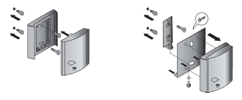
Scenario 3:
BAT Access Point installed outdoors
1
10
2
9 3
8
4
7
6 5
Figure 23: Scenario 3: BAT Access Point installed outdoors
1 Area protected by insulated lightning protection system (LPS)
2 Lightning rod
3 Safety clearance according to IEC 62305 / DIN EN 62305 (VDE 0185-
305)
4 Potential equalization line (PEL), 16 mm² Cu
5 Potential equalization line (PEL), 16 mm² Cu
6 BAT Access Point
7 BAT-LAN-Protector IP68
8 BAT-ANT-Protector m-f
9 Antenna
10 Separation distance according to IEC 62305 / DIN EN 62305 (VDE
0185-305)
In this case, the lightning protection professional installs the BAT-ANT-
Protector m-f surge protection device directly between Access Point and
antenna and grounds the BAT-ANT-Protector m-f for example via the
potential equalization line of the antenna.
WLAN Outdoor Guide Access Point
54 Release 03 08/2020Lightning protection and surge protec- 3.4 Selecting the components for
tion lightning protection and surge protec-
If you operate any Access Point installed outdoors with the supplied rod
antenna instead of an external antenna, you cannot employ the lightning
protection device BAT-ANT-Protector m-f due to the connector shape. In
this case it is imperative to employ a lightning rod!
If the Access Point is installed outdoors, the lightning protection
professional connects its grounding and that of the BAT-ANT-
Protector m-f with the conductor of the antenna, for example via the
clamps on the mounting of the antenna.
The lightning protection professional can fix the BAT-ANT-Protector
m-f directly to the antenna socket with the aid of a short adapter
(gender changer), depending on the model of the Access Point.
WLAN Outdoor Guide Access Point
Release 03 08/2020 55Lightning protection and surge protec- 3.4 Selecting the components for
tion lightning protection and surge protec-
WLAN Outdoor Guide Access Point
56 Release 03 08/2020Installation 4 Installation WLAN Outdoor Guide Release 03 08/2020 57
Installation 4.1 Mounting Notes
4.1 Mounting Notes
DANGER
LIGHTNING STRIKE AND SURGE
The installation and mounting of the Access Points and antennas may only
be carried out by a lightning protection professional. The lightning protection
professional must be familiar with the local conditions and any country-
specific safety regulations.
Also follow the instructions in chapter “Lightning protection and surge
protection” and make sure that the grounding system meets the
requirements.
Failure to follow these instructions will result in death, serious injury,
or equipment damage.
Observe the following instructions for protection against accidents:
Do not mount Access Points or antennas in weather conditions when
lightning may be expected.
Similarly, refrain from connecting or disconnecting cables during weather
of this type.
The components of a WLAN can be subject to variations in electrical
charge even in normal weather conditions. Perform all work with the
utmost care.
Make sure that the Access Points, antennas and mounting equipment
such as masts intended for outdoor use are properly grounded.
Carry out work of this type with a minimum of 2 people. This helps ensure
that help can be quicker to hand if an accident occurs despite all safety
precautions.
Only use ladders with the appropriate insulation.
Only work in dry weather without wind. If necessary, use a harness or
similar for securing.
Wear suitable working clothing, such as close-fitting clothing and safety
shoes with non-slip soles.
WLAN Outdoor Guide Access Point
58 Release 03 08/2020You can also read