Microsoft SQL Server 2012 Failover Cluster on Cisco UCS with iSCSI-Based Storage Access Deployment Guide - June 2012
←
→
Page content transcription
If your browser does not render page correctly, please read the page content below
Guide

                        Microsoft SQL Server 2012 Failover Cluster on
                        Cisco UCS with iSCSI-Based Storage Access
                        Deployment Guide
                        June 2012

© 2012 Cisco and/or its affiliates. All rights reserved. This document is Cisco Public.   Page 1 of 95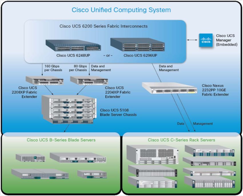
Contents
                        Executive Summary .................................................................................................................................................. 3

                        Introduction ............................................................................................................................................................... 3

                            iSCSI ...................................................................................................................................................................... 3

                            Cisco Data Center Virtual Machine Fabric Extender Technology .......................................................................... 4

                        Audience .................................................................................................................................................................... 5

                        Hardware and Software Requirements ................................................................................................................... 5

                            Cisco Unified Computing System Overview ........................................................................................................... 5

                            Cisco Unified Computing System Components ..................................................................................................... 6

                            VMware ESX 5.0 Architecture Overview .............................................................................................................. 11

                            Microsoft Windows 2008 Release 2 Overview ..................................................................................................... 12

                            Microsoft SQL Server 2012 Overview .................................................................................................................. 13

                            Overview of Microsoft SQL Server 2012 Deployment Model on Cisco UCS ....................................................... 13

                            Storage Requirements for Microsoft SQL Server Database Deployment in Virtualized Environments ............... 17

                            Advantages of iSCSI Storage Implementation on the Guest Virtual Machine and VMware ESX Host................ 17

                        Design Topology ..................................................................................................................................................... 18

                            Cisco UCS and iSCSI Storage Network............................................................................................................... 18

                            Microsoft SQL Data Network and Storage Network vPC Mapping ...................................................................... 19

                            Cisco UCS Quality-of-Service System and Policy ............................................................................................... 21

                            NetApp Storage Configuration Overview ............................................................................................................. 25

                        VMware ESX iSCSI Boot ......................................................................................................................................... 33

                        Microsoft SQL Deployment Overview ................................................................................................................... 38

                            Guest-Based iSCSI initiator on Cisco Data Center VM-FEX DVS ....................................................................... 38

                            VMware ESX Host-Based iSCSI Initiator on VMware ESX vSwitch .................................................................... 54

                            Virtual Machine–Based iSCSI Initiator on VMware ESX vSwitch ........................................................................ 62

                        Microsoft SQL Server Failover Cluster with Cisco Data Center VM-FEX DVS Solution .................................. 71

                            Physical and Logical Design ................................................................................................................................ 72

                            Installation of Microsoft Windows 2008 Failover Cluster Feature with Guest Virtual Machine–Based iSCSI
                            Software Initiator .................................................................................................................................................. 74

                            Installation of Microsoft SQL Server 2012 Failover Cluster Feature with Guest Virtual Machine–Based iSCSI
                            Storage ................................................................................................................................................................. 79

                        Conclusion............................................................................................................................................................... 94

                        References ............................................................................................................................................................... 94


© 2012 Cisco and/or its affiliates. All rights reserved. This document is Cisco Public.                                                                                                          Page 2 of 95
Executive Summary
                        The document describes the Microsoft SQL Server 2012 failover cluster deployment in a virtual computing
                        environment using the Small Computer System Interface over IP (iSCSI) protocol to communicate with storage
                                                                                                                       ®
                        devices. The document describes how to deploy Microsoft SQL Server on iSCSI using Cisco Data Center Virtual
                                                                                                                 ™              ™
                        Machine Fabric Extender (VM-FEX) technology in the Cisco Unified Computing System (Cisco UCS ). The
                        deployment scenarios discussed in this document follow Cisco UCS best practices and recommendations to help
                        ensure that the systems are highly available and scalable and can be efficiently consolidated and centrally
                        managed.

                        Introduction
                        A Microsoft SQL Server 2012 database on iSCSI storage offers a cost-effective solution for enterprise-level
                        database deployments. An inexpensive yet reliable and robust storage solution, iSCSI-based storage appliances
                        provide an easy adaption of existing networking infrastructure to access the storage enclosures. Cisco UCS can
                        exploit the bandwidth available to provide scalable, enterprise-class storage access through the iSCSI protocol.
                        Cisco UCS provides up to 80 Gbps of unified bandwidth for disk and network access for a single Cisco UCS 5108
                        Blade Server Chassis.

                        To reduce the system infrastructure cost, IT departments are trying to virtualize their computing, storage, and
                        networking infrastructure. Database server consolidation enables many companies to achieve considerable cost
                        savings, reducing the total cost of ownership (TCO). Database server consolidation can also help companies
                        achieve the infrastructure agility they need to stay competitive and to market their solutions. A Microsoft SQL
                        Server database on iSCSI storage can be easily consolidated on a virtualized platform such as VMware, and with
                        the help of Cisco Data Center VM-FEX technology, each guest virtual machine can have direct access to the iSCSI
                        device. Cisco Data Center VM-FEX technology eliminates the software switch in the hypervisor layer. Such a
                        deployment exactly mimics the bare-metal deployment and provides an easy migration path for Microsoft SQL
                        Server from bare metal to a VMware virtual machine deployment.

                        High availability is one of the primary requirements for enterprise-level database platforms because mission-critical
                        applications cannot afford to any downtime caused by unavailable databases at the network back end. Microsoft
                        SQL Server 2012 integrates with the new Microsoft Windows 2008 failover cluster service to offer failover
                        clustering, providing high availability for database applications. Coupled with iSCSI storage at the virtual machine
                        level, a clustering-enabled Microsoft SQL Server deployed on the Cisco UCS platform provides a complete back-
                        end solution with optimal TCO and high return on investment (ROI).

                        iSCSI
                        Small Computer Systems Interface (SCSI) is a standard client-server protocol that is used to enable computers to
                        communicate with storage devices. The iSCSI protocol transfers the SCSI packets over a TCP/IP (Ethernet)
                        network. The most common implementation of iSCSI is over 1 or 10 Gigabit Ethernet. The iSCSI protocol provides
                        an interoperable solution that uses the existing TCP/IP infrastructure to transport block-level storage requests.
                        Using the iSCSI protocol, systems can connect to remote storage and use it as a physical disk even if the remote
                        storage provider or target actually uses virtual physical disks.

                        An iSCSI SAN typically consists of software or hardware initiators on the host connected to an isolated Ethernet
                        network and storage resources. Storage resources are referred to as targets. The SCSI block commands are
                        encapsulated into Ethernet packets for transmission over IP networks at both the ends of the network by the
                        iSCSI stack.

© 2012 Cisco and/or its affiliates. All rights reserved. This document is Cisco Public.                                               Page 3 of 95
Advantages of iSCSI
                        Here are some of the main benefits of the iSCSI protocol compared to the SCSI protocol:

                              ●   iSCSI uses the existing TCP/IP network.
                              ●   iSCSI reduces total storage costs.
                              ●   iSCSI eliminates the distance limitation.
                              ●   iSCSI reduces complexity.
                              ●   iSCSI uses 10 Gigabit Ethernet.

                        Cisco Data Center Virtual Machine Fabric Extender Technology
                        Cisco Data Center VM-FEX is a Cisco technology that addresses management and performance concerns in a
                        data center by unifying physical and virtual switch management. Cisco Data Center VM-FEX collapses virtual and
                        physical networking into a single infrastructure. This unified infrastructure enables data center administrators to
                        provision, configure, manage, monitor, and diagnose virtual machine network traffic and bare-metal network traffic.

                        Cisco Data Center VM-FEX significantly reduces the number of network management points, enabling physical
                        and virtual network traffic to be treated in a consistent policy-based way. Cisco Data Center VM-FEX technology
                        helps enable a consistent operating model and visibility between physical and virtual environments, and it simplifies
                        enforcement of security and network policy when virtual machines are moved across hosts.

                        Cisco Data Center VM-FEX Capabilities
                        The Cisco Data Center VM-FEX software extends Cisco Fabric Extender Technology (FEX Technology) to the
                        virtual machine with the following capabilities:

                              ●   Each virtual machine includes a dedicated interface on the parent switch.
                              ●   All virtual machine traffic is sent directly to the dedicated interface on the switch.
                              ●   The software-based switch in the hypervisor is eliminated.

                        Advantages Cisco Data Center VM-FEX
                              ●   Simplicity
                                  ◦ One infrastructure for virtual and physical resource provisioning, management, monitoring, and
                                     troubleshooting
                                  ◦ Consistent features, performance, and management for virtual and physical infrastructure
                              ●   Robustness
                                  ◦ Programmable, with capability to renumber VLANs without disruptive changes
                                  ◦ Capability to troubleshoot and perform traffic engineering for virtual machine traffic from the
                                     physical network
                              ●   Performance
                                  ◦ Near-bare-metal I/O performance with VMDirectPath with VMware vMotion
                                  ◦ Delivery of the required line-rate traffic to the virtual machine

© 2012 Cisco and/or its affiliates. All rights reserved. This document is Cisco Public.                                                Page 4 of 95
Audience
                        The target audience for this guide includes sales engineers, field consultants, professional services staff, IT
                        managers, partner engineering staff, and customers who want to deploy Microsoft SQL Server on iSCSI using
                        Cisco Data Center VM-FEX.

                        Hardware and Software Requirements

                        Cisco Unified Computing System Overview
                        Cisco UCS is a set of preintegrated data center components, including blade servers, adapters, fabric
                        interconnects, and fabric extenders, that are integrated within a common embedded management system. This
                        approach results in far fewer system components and much better manageability, operation efficiencies, and more
                        flexibility than comparable data center platforms.

                        Main Differentiating Technologies
                        The main differentiating technologies described here are what make Cisco UCS unique and give it advantages
                        over competing offerings. The technologies presented here are high level, and the discussions do not include the
                        technologies (such as Fibre Channel over Ethernet [FCoE]) that support these high-level elements.

                        Unified Fabric
                        Unified fabric can dramatically reduce the number of network adapters, blade-server switches, cables, and
                        management touch points by passing all network traffic to parent fabric interconnects, where it can be prioritized,
                        processed, and managed centrally. This approach improves performance, agility, and efficiency and dramatically
                        reduces the number of devices that need to be powered, cooled, secured, and managed.

                        Embedded Multirole Management
                        Cisco UCS Manager is a centralized management application that is embedded on the fabric switch. Cisco UCS
                        Manager controls all Cisco UCS elements within a single redundant management domain. These elements include
                        all aspects of system configuration and operation, eliminating the need to use multiple, separate element managers
                        for each system component. Massive reduction in the number of management modules and consoles and in the
                        proliferation of agents resident on all the hardware (which must be separately managed and updated) are important
                        deliverables of Cisco UCS. Cisco UCS Manager, using role-based access and visibility, helps enable cross-
                        function communication efficiency, promoting collaboration between data center roles for increased productivity.

                        Cisco Extended Memory Technology
                        Significantly enhancing the available memory capacity of some Cisco UCS servers, Cisco Extended Memory
                        Technology helps increase performance for demanding virtualization and large-data-set workloads. Data centers
                        can now deploy very high virtual machine densities on individual servers as well as provide resident memory
                        capacity for databases that need only two processors but can dramatically benefit from more memory. The high-
                        memory dual in-line memory module (DIMM) slot count also lets users more cost-effectively scale this capacity
                        using smaller, less costly DIMMs.

                        Cisco Data Center VM-FEX Virtualization Support and Virtualization Adapter
                        With Cisco Data Center VM-FEX, virtual machines have virtual links that allow them to be managed in the same
                        way as physical links. Virtual links can be centrally configured and managed without the complexity of traditional
                        systems, which interpose multiple switching layers in virtualized environments. I/O configurations and network

© 2012 Cisco and/or its affiliates. All rights reserved. This document is Cisco Public.                                                   Page 5 of 95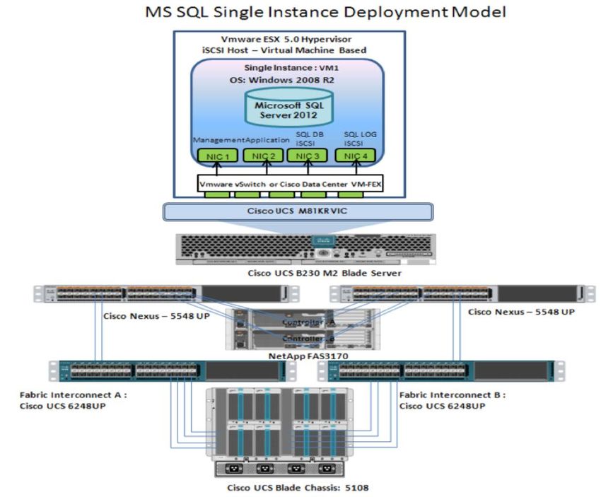
profiles move along with virtual machines, helping increase security and efficiency while reducing complexity. Cisco
                        Data Center VM-FEX helps improve performance and reduce network interface card (NIC) infrastructure.

                        Dynamic Provisioning with Service Profiles
                        Cisco UCS Manager delivers service profiles, which contain abstracted server-state information, creating an
                        environment in which everything unique about a server is stored in the fabric, and the physical server is simply
                        another resource to be assigned. Cisco UCS Manager implements role- and policy-based management focused on
                        service profiles and templates. These mechanisms fully provision one or many servers and their network
                        connectivity in minutes, rather than hours or days.

                        Cisco UCS Manager
                        Cisco UCS Manager is an embedded, unified manager that provides a single point of management for Cisco UCS.
                        Cisco UCS Manager can be accessed through an intuitive GUI, a command-line interface (CLI), or the
                        comprehensive open XML API. It manages the physical assets of the server and storage and LAN connectivity,
                        and it is designed to simplify the management of virtual network connections through integration with several major
                        hypervisor vendors. It provides IT departments with the flexibility to allow people to manage the system as a whole,
                        or to assign specific management functions to individuals based on their roles as managers of server, storage, or
                        network hardware assets. It simplifies operations by automatically discovering all the components available on the
                        system and enabling a stateless model for resource use.

                        The elements managed by Cisco UCS Manager include:

                              ●   Cisco UCS Integrated Management Controller (IMC) firmware
                              ●   RAID controller firmware and settings
                              ●   BIOS firmware and settings, including server universal user ID (UUID) and boot order
                              ●   Converged network adapter (CNA) firmware and settings, including MAC addresses and worldwide names
                                  (WWNs) and SAN boot settings
                              ●   Virtual port groups used by virtual machines, using Cisco Data Center VM-FEX technology
                              ●   Interconnect configuration, including uplink and downlink definitions, MAC address and WWN pinning,
                                  VLANs, VSANs, quality of service (QoS), bandwidth allocations, Cisco Data Center VM-FEX settings, and
                                  EtherChannels to upstream LAN switches

                        Cisco Unified Computing System Components
                        Figure 1 shows the Cisco UCS components.

© 2012 Cisco and/or its affiliates. All rights reserved. This document is Cisco Public.                                              Page 6 of 95
Figure 1.      Cisco UCS Components

                        Cisco UCS is designed from the start to be programmable and self-integrating. A server’s entire hardware stack,
                        ranging from server firmware and settings to network profiles, is configured through model-based management.
                        With Cisco virtual interface cards (VICs), even the number and type of I/O interfaces is programmed dynamically,
                        making every server ready to power any workload at any time.

                        With model-based management, administrators manipulate a model of a desired system configuration and
                        associate a model’s service profile with hardware resources, and the system configures itself to match the model.
                        This automation accelerates provisioning and workload migration with accurate and rapid scalability. The result is
                        increased IT staff productivity, improved compliance, and reduced risk of failures due to inconsistent
                        configurations.

                        Cisco FEX Technology reduces the number of system components that need to be purchased, configured,
                        managed, and maintained by condensing three network layers into one. It eliminates both blade server and
                        hypervisor-based switches by connecting fabric interconnect ports directly to individual blade servers and virtual
                        machines. Virtual networks are now managed exactly the same way that physical networks are, but enable
                        massive scalability. This approach represents a radical simplification compared to traditional systems, reducing

© 2012 Cisco and/or its affiliates. All rights reserved. This document is Cisco Public.                                              Page 7 of 95
capital expenditures (CapEx) and operating expenses (OpEx) while increasing business agility, simplifying and
                        accelerating deployment, and improving performance.

                        Cisco UCS Fabric Interconnects
                        Cisco UCS fabric interconnects create a unified network fabric throughout Cisco UCS. They provide uniform
                        access to both networks and storage, eliminating the barriers to deployment of a fully virtualized environment
                        based on a flexible, programmable pool of resources. Cisco fabric interconnects comprise a family of line-rate, low-
                        latency, lossless 10 Gigabit Ethernet, IEEE Data Center Bridging (DCB), and FCoE interconnect switches. Based
                                                                                          ®
                        on the same switching technology as the Cisco Nexus 5000 Series Switches, Cisco UCS 6100 Series Fabric
                        Interconnects provide additional features and management capabilities that make them the central nervous system
                        of Cisco UCS. The Cisco UCS Manager software runs inside the Cisco UCS fabric interconnects. The Cisco UCS
                        6100 Series Fabric Interconnects expand the Cisco UCS networking portfolio and offer higher capacity, higher port
                        density, and lower power consumption. These interconnects provide the management and communication
                        backbone for the Cisco UCS B-Series Blade Servers and Cisco UCS blade server chassis. All chassis and all
                        blades that are attached to interconnects are part of a single, highly available management domain. By supporting
                        unified fabric, the Cisco UCS 6100 Series provides the flexibility to support LAN and SAN connectivity for all blades
                        within its domain at configuration time. Typically deployed in redundant pairs, Cisco UCS fabric interconnects
                        provide uniform access to both networks and storage, facilitating a fully virtualized environment.

                        The Cisco UCS fabric interconnect portfolio currently consists of the Cisco 6100 and 6200 Series Fabric
                        Interconnects.

                        Cisco UCS 6248UP 48-Port Fabric Interconnect
                        The Cisco UCS 6248UP 48-Port Fabric Interconnect is a one-rack-unit (1RU) 10 Gigabit Ethernet, IEEE DCB, and
                        FCoE interconnect providing more than 1-terabit-per-second (Tbps) throughput with low latency. It has 32 fixed
                        ports of Fibre Channel, 10 Gigabit Ethernet, IEEE DCB, and FCoE Enhanced Small Form-Factor Pluggable (SFP+)
                        ports.

                        One expansion module slot can provide up to 16 additional Fibre Channel, 10 Gigabit Ethernet, IEEE DCB, and
                        FCoE SFP+ ports.

                        Cisco UCS 6120XP 20-Port Fabric Interconnect
                        The Cisco UCS 6120XP 20-Port Fabric Interconnect is a 1RU 10 Gigabit Ethernet, IEEE DCB, and FCoE
                        interconnect providing more than 500-Gbps throughput with very low latency. It has 20 fixed 10 Gigabit Ethernet,
                        IEEE DCB, and FCoE SFP+ ports.

                        One expansion module slot can be configured to support up to six additional 10 Gigabit Ethernet, IEEE DCB, and
                        FCoE SFP+ ports.

                        Cisco UCS 6140XP 40-Port Fabric Interconnect
                        The Cisco UCS 6140XP 40-Port Fabric Interconnect is a 2RU 10 Gigabit Ethernet, IEEE DCB, and FCoE
                        interconnect built to provide 1.04-Tbps throughput with very low latency. It has 40 fixed 10 Gigabit Ethernet, IEEE
                        DCB, and FCoE SFP+ ports.

                        Two expansion module slots can be configured to support up to 12 additional 10 Gigabit Ethernet, IEEE DCB, and
                        FCoE SFP+ ports.

© 2012 Cisco and/or its affiliates. All rights reserved. This document is Cisco Public.                                              Page 8 of 95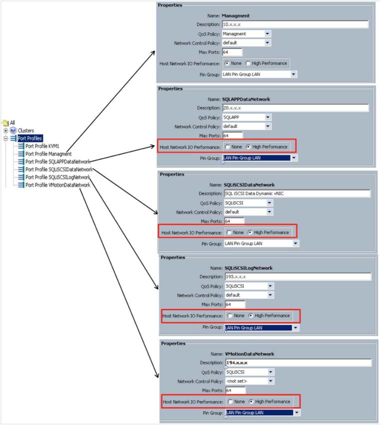
Cisco UCS 6296UP 96-Port Fabric Interconnect
                        The Cisco UCS 6296UP 96-Port Fabric Interconnect is a 2RU 10 Gigabit Ethernet, FCoE, and native Fibre
                        Channel switch offering up to 1920-Gbps throughput and up to 96 ports. The switch has 48 1/10-Gbps fixed
                        Ethernet, FCoE, and Fibre Channel ports and three expansion slots.

                        One expansion module slot can provide up to 16 additional Fibre Channel, 10 Gigabit Ethernet, IEEE DCB, and
                        FCoE SFP+ ports.

                        Cisco UCS 2100 and 2200 Series Fabric Extenders
                        The Cisco UCS 2100 and 2200 Series Fabric Extenders multiplex and forward all traffic from blade servers in a
                        chassis to a parent Cisco UCS fabric interconnect over 10-Gbps unified fabric links. All traffic, even traffic between
                        blades on the same chassis or virtual machines on the same blade, is forwarded to the parent interconnect, where
                        network profiles are managed efficiently and effectively by the fabric interconnect. At the core of the Cisco UCS
                        fabric extender are application-specific integrated circuit (ASIC) processors developed by Cisco that multiplex
                        all traffic.

                        Up to two fabric extenders can be placed in a blade chassis.

                              ●   The Cisco UCS 2104XP Fabric Extender has eight 10GBASE-KR connections to the blade chassis
                                  midplane, with one connection per fabric extender for each of the chassis’ eight half slots. This configuration
                                  gives each half-slot blade server access to each of two 10-Gbps unified fabric-based networks through
                                  SFP+ sockets for both throughput and redundancy. It has four ports connecting the fabric interconnect.
                              ●   The Cisco UCS 2204XP Fabric Extender has four 10 Gigabit Ethernet, FCoE-capable, SFP+ ports that
                                  connect the blade chassis to the fabric interconnect. Each Cisco UCS 2204XP has sixteen 10 Gigabit
                                  Ethernet ports connected through the midplane to each half-width slot in the chassis. Typically configured in
                                  pairs for redundancy, two fabric extenders provide up to 80 Gbps of I/O to the chassis.
                              ●   The Cisco UCS 2208XP Fabric Extender has eight 10 Gigabit Ethernet, FCoE-capable, SFP+ ports that
                                  connect the blade chassis to the fabric interconnect. Each Cisco UCS 2208XP has thirty-two 10 Gigabit
                                  Ethernet ports connected through the midplane to each half-width slot in the chassis. Typically configured in
                                  pairs for redundancy, two fabric extenders provide up to 160 Gbps of I/O to the chassis.

                        Cisco UCS M81KR Virtual Interface Card
                        The Cisco UCS M81KR VIC is unique to the Cisco UCS blade system. This mezzanine adapter is designed based
                        on a custom ASIC that is specifically intended for virtualized systems based on VMware. It uses custom drivers for
                        the virtualized host bus adapter (HBA) and the 10 Gigabit Ethernet NIC. As is the case with the other Cisco CNAs,
                        the Cisco UCS M81KR VIC encapsulates Fibre Channel traffic within the 10 Gigabit Ethernet packets for delivery
                        to the fabric extender and the fabric interconnect.

                        Cisco UCS Virtual Interface Card 1240
                        A Cisco innovation, the Cisco UCS VIC 1240 is a four-port 10 Gigabit Ethernet, FCoE-capable modular LAN on
                        motherboard (mLOM) designed exclusively for the M3 generation of Cisco UCS B-Series Blade Servers. When
                        used in combination with an optional port expander, the Cisco UCS VIC 1240 capabilities can be expanded to eight
                        ports of 10 Gigabit Ethernet.

© 2012 Cisco and/or its affiliates. All rights reserved. This document is Cisco Public.                                                  Page 9 of 95
Cisco UCS Virtual Interface Card 1280
                        A Cisco innovation, the Cisco UCS VIC 1280 is an eight-port 10 Gigabit Ethernet, FCoE-capable mezzanine card
                        designed exclusively for Cisco UCS B-Series Blade Servers.

                        The Cisco UCS VIC 1240 and 1280 enable a policy-based, stateless, agile server infrastructure that can present
                        up to 256 PCI Express (PCIe) standards-compliant interfaces to the host that can be dynamically configured as
                        either NICs or HBAs. In addition, the Cisco UCS VIC 1280 supports Cisco Data Center VM-FEX technology, which
                        extends the Cisco UCS fabric interconnect ports to virtual machines, simplifying server virtualization deployment.

                        Cisco UCS 5100 Series Blade Server Chassis
                        The Cisco UCS 5108 Blade Server Chassis is a 6RU blade chassis that accepts up to eight half-width Cisco UCS
                        B-Series Blade Servers or up to four full-width Cisco UCS B-Series Blade Servers, or a combination of the two.
                        The Cisco UCS 5108 can accept four redundant power supplies with automatic load sharing and failover and two
                        Cisco UCS 2100 or 2200 Series Fabric Extenders. The chassis is managed by Cisco UCS chassis management
                        controllers, which are mounted in the Cisco UCS fabric extenders and work in conjunction with Cisco UCS
                        Manager to control the chassis and its components.

                        A single Cisco UCS managed domain can theoretically scale to up to 40 individual chassis and 320 blade servers.
                        At this time, Cisco UCS supports up to 20 individual chassis and 160 blade servers.

                        Basing the I/O infrastructure on a 10-Gbps unified network fabric allows Cisco UCS to have a streamlined chassis
                        with a simple yet comprehensive set of I/O options. The result is a chassis that has only five basic components:

                              ●   The physical chassis with passive midplane and active environmental monitoring circuitry
                              ●   Four power supply bays with power entry in the rear and hot-swappable power supply units accessible from
                                  the front panel
                              ●   Eight hot-swappable fan trays, each with two fans
                              ●   Two fabric extender slots accessible from the back panel
                              ●   Eight blade server slots accessible from the front panel

                        Cisco UCS B200 M2 Blade Servers
                        The Cisco UCS B200 M2 Blade Server is a half-slot, 2-socket blade server. The system uses two Intel Xeon p5600
                        series processors, up to 192 GB of double-data-rate-3 (DDR3) memory, two optional Small Form Factor (SFF)
                        SAS/SSD disk drives, and a single CNA mezzanine slot for up to 20 Gbps of I/O throughput. The Cisco UCS B200
                        M2 Blade Server balances simplicity, performance, and density for production-level virtualization and other
                        mainstream data center workloads.

                        Cisco UCS B250 M2 Extended Memory Blade Servers
                        The Cisco UCS B250 M2 Extended-Memory Blade Server is a full-slot, 2-socket blade server using Cisco
                        Extended Memory Technology. The system supports two Intel Xeon processors 5600 series, up to 384 GB of
                        DDR3 memory, two optional SFF SAS/SSD disk drives, and two CNA mezzanine slots for up to 40 Gbps of I/O
                        throughput. The Cisco UCS B250 M2 blade server provides increased performance and capacity for demanding
                        virtualization and large-data-set workloads, with greater memory capacity and throughput.

                        Cisco UCS B230 M2 Blade Servers
                        The Cisco UCS B230 M2 Blade Server is a full-slot, 2-socket blade server offering the performance and reliability
                        of the Intel Xeon processor E7-2800 product family and up to 32 DIMM slots, which support up to 512 GB of
© 2012 Cisco and/or its affiliates. All rights reserved. This document is Cisco Public.                                               Page 10 of 95
memory. The Cisco UCS B230 M2 supports two SSD drives and one CNA mezzanine slot for up to 20 Gbps of I/O
throughput. The Cisco UCS B230 M2 Blade Server platform delivers outstanding performance, memory, and I/O
capacity to meet the diverse needs of virtualized environments with advanced reliability and exceptional scalability
for the most demanding applications.
Cisco UCS B440 M2 High-Performance Blade Servers
The Cisco UCS B440 M2 High-Performance Blade Server is a full-slot, 2-socket blade server offering the
performance and reliability of the Intel Xeon processor E7-4800 product family and up to 512 GB of memory. The
Cisco UCS B440 M2 supports four SFF SAS/SSD drives and two CNA mezzanine slots for up to 40 Gbps of I/O
throughput. The Cisco UCS B440 M2 blade server extends Cisco UCS by offering increased levels of performance,
scalability, and reliability for mission-critical workloads.
Cisco UCS B200 M3 Blade Servers
The Cisco UCS B200 M3 Blade Server delivers performance, versatility, and density without compromise. It
addresses the broadest set of workloads, from IT and web infrastructure to distributed databases. Building on the
success of the Cisco UCS B200 M2 Blade Server, the enterprise-class Cisco UCS B200 M3 Blade Server further
extends the capabilities of the Cisco UCS portfolio in a half-width blade form factor. The Cisco UCS B200 M3
harnesses the power of the latest Intel Xeon processor E5-2600 product family, with up to 384 GB of RAM (using
16-GB DIMMs), two disk drives, and up to dual 4x 10 Gigabit Ethernet throughput. In addition, Cisco UCS has the
architectural advantage of not having to power and cool excess switches in each blade chassis. With a larger
power budget per blade server, Cisco can design uncompromised expandability and capabilities in its blade
servers, as evidenced by the new Cisco UCS B200 M3, with its leading memory slot and drive capacity.
VMware ESX 5.0 Architecture Overview
VMware ESX is an enterprise-level computer virtualization solution. VMware ESX is a production-proven
virtualization layer that runs on physical servers that abstract processor, memory, storage, and networking
resources to be provisioned to multiple virtual machines.
In the VMware ESX architecture, shown in Figure 2, the VMware Virtualization Kernel (VMkernel) is augmented by
a management partition known as the console operating system or service console. The primary purpose of the
console operating system is to provide a management interface with the host. Various VMware management
agents are deployed in the console operating system, along with other infrastructure service agents (for example,
name service, time service, and logging agents). Furthermore, individual administrative users can log in to the
console operating system to run configuration and diagnostic commands and scripts.
Figure 2. VMware ESX 5.0 Architecture
© 2012 Cisco and/or its affiliates. All rights reserved. This document is Cisco Public. Page 11 of 95Virtualization using VMware ESX provides an abstraction layer that decouples the physical hardware from the
operating system to deliver greater IT resource utilization and flexibility. Virtualization allows multiple virtual
machines with heterogeneous operating systems (for example, Microsoft Windows 2008 Server and Linux) and
applications to run in isolation side by side on the same physical machine. A virtual machine is the representation
of a physical machine by software. It has its own set of virtual hardware (RAM, CPU, NICs, hard disks, etc.) on
which an operating system and applications are loaded. The operating system sees a consistent, normalized set of
hardware regardless of the actual physical hardware components. VMware virtual machines contain advanced
hardware features such as 64-bit computing and virtual symmetric multiprocessing. Figure 3 shows server
virtualization with VMware ESX in which virtual machines directly access the network through Cisco Data Center
VM-FEX.
Figure 3. VMware ESX 5.0 with Cisco Data Center VM-FEX
Microsoft Windows 2008 Release 2 Overview
Microsoft Windows Server 2008 Release 2 (R2) is Microsoft’s multipurpose next-generation operating system
designed to increase reliability and flexibility. Microsoft Windows Server 2008 R2 introduces powerful next-
generation tools, built-in virtualization technology, and security and server management enhancements to
efficiently manage IT operations, reduce costs, and improve performance of business-critical systems. The main
improvements offered in Microsoft Windows Server 2008 R2 are:
© 2012 Cisco and/or its affiliates. All rights reserved. This document is Cisco Public. Page 12 of 95● Improved scalability and reliability: Microsoft Windows Server 2008 R2 is specifically designed to support
increased workloads while using fewer resources.
● Technology improvements: Microsoft Windows Server 2008 R2 includes technology improvements
designed with Microsoft Windows 7 enterprise users in mind, augmenting the network experience, security,
and manageability.
● Improved management: Microsoft Windows Server 2008 R2 provides enhanced management consoles and
automation for repetitive day-to-day administrative tasks.
● Improved web application platform: Microsoft Windows Server 2008 R2 provides the capability to deliver
web-based multimedia experiences efficiently and effectively, with improved administration, diagnostic,
development, and application tools and lower infrastructure costs.
● Microsoft Remote Desktop Services (RDS): Microsoft RDS enables users to access applications, data, and
even an entire desktop running in the data center over the network. This capability provides both the
features and the robustness of a proven solution, giving users flexible access to their data and applications.
Microsoft SQL Server 2012 Overview
Microsoft SQL Server is an enterprise-class relational database management system (RDBMS) that runs on the
Microsoft Windows platform and provides a wide range of data management, data integration (including data
quality), and business intelligence capabilities.
Some of the main features of Microsoft SQL Server 2012 are:
● High availability, including support for active multiple secondary databases, faster failover performance, fast
setup, and integrated management
● ColumnStore Index, enabling the caching of query-critical data from the data warehouse in memory-based
columnar format and delivering on average 10 times the query performance of prior versions of Microsoft
SQL Server
● Support for Microsoft Windows Server Core to enable better reliability and thorough cross-system security
through a reduced surface area
● The new Microsoft Power View browser–based tool, along with enhancements to the Microsoft PowerPivot
feature, providing rapid insight through self-service data exploration, visualization, and data mashup
capabilities (users can collaborate and share these insights through Microsoft SharePoint)
● A new single business intelligence semantic model and data quality services that help provide credible,
consistent data
● Support for big data through bidirectional connectors for Hadoop along with enhancements for creation of
massively scalable analytics and data warehouse solutions
● Cloud-ready connectivity built with features that support hybrid IT (integrating on-premises systems with
public and private clouds)
● Expanded support for unstructured data and greater interoperability with PHP, Java, and Linux
Overview of Microsoft SQL Server 2012 Deployment Model on Cisco UCS
This document describes two Microsoft SQL Server deployment models:
● Microsoft SQL Server single-instance deployment model
● Microsoft SQL Server failover cluster deployment model
© 2012 Cisco and/or its affiliates. All rights reserved. This document is Cisco Public. Page 13 of 95Microsoft SQL Server Single-Instance Deployment Model
In the single-instance model, multiple applications are moved onto a single physical server with multiple Microsoft
SQL Server instances. Each application is contained within its own Microsoft SQL Server instance. This model
provides isolation of the Microsoft SQL Server instance binaries, allowing each application to be at a different patch
level (major or minor version level). However, conflicts can potentially occur with the running application because
system resources (mainly CPU, memory, and I/O) are shared, although tools such as the CPU affinity mask and
max server memory settings can help provide resource isolation. Database system administration is isolated, but
Microsoft Windows system administration shares the same host server. Each Microsoft SQL Server instance on
the device can be enrolled within a Microsoft SQL Server control point for management. Another possible
implementation is consolidation of several databases under a single Microsoft SQL Server instance to serve
various applications. In this model, a single Microsoft SQL Server instance is shared across multiple applications,
with each application having its own database.
With the single-instance approach, applications migrated from their physical server to a virtual machine
environment can continue to have similar isolation with the Microsoft SQL Server database running on its own
virtual machine. A single physical machine hosts multiple virtual machines, and each virtual machine hosts a single
Microsoft SQL Server instance. Because a virtual machine can act as a dedicated physical machine, this approach
provides an easier migration of the source environment to the consolidation environment. The single-instance
deployment model is shown in Figure 4.
© 2012 Cisco and/or its affiliates. All rights reserved. This document is Cisco Public. Page 14 of 95Figure 4. Microsoft SQL Server Single-Host Deployment Model
Microsoft SQL Failover Cluster Deployment Model
The Microsoft SQL cluster deployment model allows one Microsoft SQL Server to take over the tasks and
responsibilities of another Microsoft SQL Server that has failed. This model helps ensure that users running
mission-critical applications experience little or no downtime when such a failure occurs. Downtime can be very
expensive, and the database administrator can help reduce it as much as possible. Microsoft SQL Server
clustering is a high-availability technology for Microsoft SQL Server instances. It involves the sharing of server
resources between one or more nodes (or servers), which have one or more shared disks grouped into logical
units called resource groups. A resource group that contains at least one IP address, network name, and disk
resource is called a virtual server. The cluster service arbitrates ownership of the resource groups. A single node
can own a resource group and its associated resources at any given time.
The Microsoft SQL Server cluster deployment model is shown in Figure 5. Two nodes that are members of the
Microsoft Windows 2008 R2 failover cluster service are deployed on VMware ESX virtual machines on two
separate Cisco UCS blades. Both VMware ESX and the guest virtual machine (Microsoft Windows 2008 R2) are
booted from a logical unit number (LUN) hosted on a NetApp FAS3270 with access through the iSCSI protocol.
© 2012 Cisco and/or its affiliates. All rights reserved. This document is Cisco Public. Page 15 of 95The quorum disk for the failover cluster is also accessed through the iSCSI protocol. The database data and log
files are stored on separate LUNs carved out of NetApp FAS3270. These LUNs are accessed through the iSCCI
initiator originating in both the host and guest virtual machines.
This design demonstrates the flexibility of accessing storage through the iSCSI protocol with either the host-based
iSCSI initiator or guest virtual machine–based iSCSI initiator. With universal passthrough (UPT) enabled on the
virtual NICs (vNICs), guest virtual machines can access LUNs directly without having to go through the hypervisor
layer, eliminating the additional overhead incurred while accessing critical storage resources. With UPT enabled for
the iSCSI initiator, you get better response times and higher bandwidth with less CPU use on the VMware ESX
host.
Figure 5. Microsoft SQL Server Failover Cluster Deployment Model
© 2012 Cisco and/or its affiliates. All rights reserved. This document is Cisco Public. Page 16 of 95Storage Requirements for Microsoft SQL Server Database Deployment in Virtualized Environments
Storage configuration is critical to any successful database deployment. As with any physical Microsoft SQL Server
deployment, the storage in virtualized environments should be sized properly to meet the database I/O
requirements. The two important considerations for sizing the storage requirements are:
● Database size measured in GB
● Performance capacity measured by the number of I/O operations per second (IOPS) needed for the
database to operate efficiently
To successfully design and deploy storage for a Microsoft SQL Server application, you need to understand the
application’s I/O characteristics and the Microsoft SQL Server I/O patterns. You need to consider parameters such
as the read-to-write ratio of the application and typical I/O rates to configure the I/O characteristics of the
application. The number of spindles and the speed should be configured to the maximum possible to increase
storage performance. RAID 1+0 provides a better throughput for write-intensive applications. Place log files on
RAID 1+0 (or RAID 1) disks for better performance and protection from hardware failures.
This validated solution uses the iSCSI protocol to access the primary database application storage.
Advantages of iSCSI Storage Implementation on the Guest Virtual Machine and VMware ESX Host
The iSCSI protocol allows SCSI commands to be sent over a TCP/IP network. iSCSI uses standard IP network
equipment such as Ethernet switches and standard NICs to send SCSI block commands encapsulated in IP
packets.
iSCSI offers the following advantages:
● iSCSI uses the existing IP networks and components (NICs, switches, cables, etc.), and therefore a
separate network is not required to create the SAN.
● An iSCSI SAN is cost effective compared to a Fibre Channel SAN.
● An iSCSI-based SAN can coexist with the current Fibre Channel–based SAN. This feature gives customers
using Fibre Channel the flexibility to scale up their SANs by adding storage capacity using an iSCSI SAN.
● An iSCSI SAN does not have any distance limitation.
● iSCSI is easy to learn, deploy, and maintain because it uses common IP-based network components.
● iSCSI is well suited for implementation of SANs in virtual server environments because it supports software
initiators that make such integration easier.
● iSCSI supports the same amount of bandwidth as IP networks and therefore can provide the high
bandwidth required for virtual server environments.
● iSCSI supports direct backup to tapes or disks even from virtual servers.
NetApp Storage Technologies and Benefits
NetApp solutions begin with NetApp Data ONTAP 8.0.1, the fundamental software platform that runs on all NetApp
storage systems. NetApp Data ONTAP 8.0.1 is a highly optimized, scalable operating system that supports mixed
network-attached storage (NAS) and SAN environments and a range of protocols, including Fibre Channel, iSCSI,
FCoE, Network File System (NFS), and Common Internet File System (CIFS). It also includes a patented file
system and storage virtualization capabilities. Using the NetApp Data ONTAP 8.0.1 platform, the NetApp unified
storage architecture offers the flexibility to manage, support, and scale business environments by using a single set
of knowledge and tools. From the remote office to the data center, customers collect, distribute, and manage data
© 2012 Cisco and/or its affiliates. All rights reserved. This document is Cisco Public. Page 17 of 95from all locations and applications at the same time, scaling their investment by standardizing processes, reducing
management time, and increasing availability. Figure 6 shows the NetApp unified storage architecture platforms.
Figure 6. NetApp Unified Storage Architecture
The NetApp storage hardware platform used in this solution is the NetApp FAS3270. The NetApp FAS3200 series
is an excellent platform for Microsoft SQL Server 2012 deployments.
A variety of NetApp tools and enhancements are available to augment the storage platform. These tools assist in
deployment, backup, recovery, replication, management, and data protection. This solution uses a subset of these
tools and enhancements.
Design Topology
This section presents physical and logical high-level design considerations for Cisco UCS networking and
computing with VMware ESX virtualization on NetApp storage for Microsoft SQL Server 2012 failover cluster
deployments.
Cisco UCS and iSCSI Storage Network
This section explains Cisco UCS iSCSI networking and computing design considerations when deploying Microsoft
SQL Server in a VMware ESX environment. In this design, the iSCSI traffic is isolated from the regular
management and application data network using the same Cisco UCS infrastructure by defining logical VLAN
networks to provide better data security. This design also reduces OpEx and CapEx compared to a topology in
which a separate dedicated physical switch is deployed to handle iSCSI traffic.
Figure 7 presents a detailed view of the physical topology, identifying the various levels of the architecture and
some of the main components of Cisco UCS in an iSCSI network design.
© 2012 Cisco and/or its affiliates. All rights reserved. This document is Cisco Public. Page 18 of 95Figure 7. Cisco UCS Component in iSCSI Network Design
As shown in Figure 7, a pair of Cisco UCS 6248UP fabric interconnects carries both storage and network traffic
from the blades with the help Cisco Nexus 5548UP. Both the fabric interconnect and the Cisco Nexus 5548UP are
clustered with the peer link between them to provide high availability. Two virtual PortChannels (vPCs) are
configured to provide network and storage access paths for the blades to northbound switches. Each vPC has
VLANs created for application network data, iSCSI storage data, and management data paths. There is also a
dedicated VLAN for VMware vMotion data traffic for VMware ESX Server.
For more information about vPC configuration on the Cisco Nexus 5548UP Switch, see
http://www.cisco.com/en/US/prod/collateral/switches/ps9441/ps9670/configuration_guide_c07-543563.html.
Microsoft SQL Data Network and Storage Network vPC Mapping
Table 1 shows the Cisco Nexus 5548UP vPC configurations with the vPC domains and corresponding vPC names
and IDs for Microsoft SQL Servers. To provide Layer 2 and 3 switching, a pair of Cisco Nexus 5548UP Switches
with upstream switching are deployed, providing high availability in the event of failure to Cisco UCS to handle
management, application, and iSCSI storage data traffic. In the Cisco Nexus 5548UP topology, a single vPC
feature is enabled to provide high availability, faster convergence in the event of a failure, and greater throughput.
Table 1. vPC Mapping
vPC Domain vPC Name vPC ID
100 vPC-MS SQL 1 101
100 vPC-MS SQL 2 102
100 vPC-iSCSI Storage 1 103
100 vPC-iSCSI Storage 2 104
In the vPC design table, a single vPC domain, Domain 100, is created across Cisco Nexus 5548UP member
switches to define vPCs to carry specific network traffic. This topology defines four vPCs with IDs 101 through 104.
© 2012 Cisco and/or its affiliates. All rights reserved. This document is Cisco Public. Page 19 of 95vPC IDs 101 and 102 are defined for traffic from Cisco UCS fabric interconnects, and vPC IDs 103 and 104 are
defined for traffic to NetApp storage. These vPCs are managed within the Cisco Nexus 5548UP, which connects
Cisco UCS fabric interconnects and the NetApp storage system.
When configuring the Cisco Nexus 5548UP with vPCs, be sure that the status for all vPCs is “Up” for connected
Ethernet ports by running the commands shown in Figure 8 from the CLI on the Cisco Nexus 5548UP Switch.
Figure 8. PortChannel Status on Cisco Nexus 5548UP
Table 2 shows the vPC configuration details for Cisco UCS 6248UP Fabric Interconnects A and B with the required
vPC IDs, VLAN IDs, and Ethernet uplink ports for a Microsoft SQL Server data network design.
Table 2. Fabric Interconnects A and B (Microsoft SQL Server Data Network)
vPC Name vPC ID LAN Uplink Ports VLAN ID
vPC-MS SQL 1 101 Fabric Interconnect A 108 (management)
(Eth 1/15 and 1/16) 109 (SQL network)
192 (iSCSI storage)
194 (VMware vMotion)
vPC-MS SQL 2 102 Fabric Interconnect B 108 (management)
(Eth 1/15 and 1/16) 109 (SQL network)
192 (iSCSI storage)
194 (VMware vMotion)
On Cisco UCS Fabric Interconnect A, Ethernet uplink ports 15 and 16 are connected to Cisco Nexus 5548UP
Application 1 (port 13) and Cisco Nexus 5548UP Application 2 (port 13), which are part of vPC ID 101 and have
access to VLAN IDs 108, 109, 192, and 194. The same configuration is replicated for vPC ID 102 on Fabric
interconnect B, with ports 15 and 16 connected to port 14 of Cisco Nexus 5548UP Application 1 and Cisco Nexus
5548UP Application 2.
After configuring Cisco UCS 6248UP Fabric Interconnects A and B with vPCs, make sure that the status of all the
PortChannels is “Enabled,” as shown in the Cisco UCS Manager screen in Figure 9.
© 2012 Cisco and/or its affiliates. All rights reserved. This document is Cisco Public. Page 20 of 95Figure 9. Uplink Interfaces and PortChannel Status
On the Cisco Nexus 5548UP Switch, a separate vPC is created to access NetApp shared iSCSI storage. The vPC
is created with the vPC name and corresponding vPC ID and required VLAN IDs, as shown in Table 3.
Table 3. NetApp Storage
vPC Name iSCSI Ports vPC ID VLAN ID
(Controllers A and B)
vPC- iSCSI Storage 1 e1b and e1c (Controller A) 103 192
vPC- iSCSI Storage 2 e1b and e1c (Controller B) 104 192
On NetApp Storage Controller A, Ethernet 10-Gbps port e1b is connected to Cisco Nexus 5548UP Application 1
(port 19), and Ethernet port e1c is connected to Cisco Nexus 5548UP Application 2 (port 19), which are part of
vPC-iSCSI Storage 1 with vPC ID 103 that allows traffic from VLAN ID 192. On NetApp Storage Controller B,
Ethernet 10-Gbps port e1b is connected to Cisco Nexus 5548UP Application 1 (port 20), and Ethernet port e1c is
connected to Cisco Nexus 5548UP Application 2 (port 20), which are part of vPC-iSCSI Storage 2 with vPC ID 104
that allows traffic from VLAN ID 192.
Cisco UCS Quality-of-Service System and Policy
Cisco UCS uses IEEE Data Center Bridging (DCB) to handle all traffic within Cisco UCS. This industry-standard
enhancement to Ethernet divides the bandwidth of the Ethernet pipe into eight virtual lanes. System classes
determine how the DCB bandwidth in these virtual lanes is allocated across the entire Cisco UCS platform.
Each system class reserves a specific segment of the bandwidth for a specific type of traffic, providing an assured
level of traffic management even in an oversubscribed system. For example, you can configure the Fibre Channel
Priority system class to determine the percentage of DCB bandwidth allocated to FCoE traffic.
Table 4 describes the system classes.
© 2012 Cisco and/or its affiliates. All rights reserved. This document is Cisco Public. Page 21 of 95Table 4. System Classes
System Class Description
● Platinum Priority These classes set the quality of service (QoS) for all servers that include one of these system classes in the
● Gold Priority QoS definition in the service profile associated with the server. Each of these system classes manages one
lane of traffic. All properties of these system classes are available for you to assign custom settings and
● Silver Priority policies.
● Bronze Priority
Best-Effort Priority This class sets the QoS for the lane that is reserved for basic Ethernet traffic. Some properties of this system
class are preset and cannot be modified. For example, this class has a drop policy to allow it to drop data
packets if required.
Fibre Channel Priority This class sets the QoS for the lane that is reserved for FCoE traffic. Some properties of this system class are
preset and cannot be modified. For example, this class has a no-drop policy to help ensure that it never drops
data packets.
QoS policies assign a system class to the outgoing traffic for a vNIC or virtual HBA (vHBA). You must include a
QoS policy in a vNIC policy and then include that policy in a service profile to configure the vNIC.
To provide efficient network utilization and bandwidth control in a Microsoft SQL Server environment on VMware
ESX over an iSCSI network, QoS system classes and corresponding policies are defined for network traffic
generated by iSCSI storage, VMware vMotion, and the Microsoft SQL Server application and guest virtual machine
management network in Cisco UCS as explained here:
● iSCSI storage traffic requires high bandwidth and a fast response time to access Microsoft SQL Server log
data in the shared storage. To meet this requirement, a SQLLog QoS policy is created and defined with the
Platinum class with the highest weight (bandwidth) and a maximum transmission unit (MTU) of 9000 for
handling Microsoft SQL Server log transactions, which have a sequential I/O access pattern.
● To handle Microsoft SQL Server database data traffic, which have a more random I/O pattern and are less
I/O intensive than log traffic, a SQLDB QoS policy is created with the Gold class with the second highest
weight (bandwidth) and an MTU of 9000 to handle iSCSI packets.
● To handle VMware vMotion kernel traffic across a VMware ESX cluster during dynamic resource scheduler
or manual intervention, VMware ESX requires dedicated network bandwidth for copying virtual machine
active memory data. To meet this requirement, SQLVMotion QoS policy is created and is defined with the
Silver class and with the third highest weight (bandwidth) and an MTU of 9000 to handle jumbo VMkernel
packets from vNICs (static) in the service profiles in which the VMware ESX host is installed, which is a part
of the VMware ESX host-based iSCSI environment.
● To handle Microsoft SQL Server application data traffic from clients on the network that are not I/O intensive
compared to Microsoft SQL Server database data and log traffic and VMware vMotion traffic, a Bronze QoS
class with the fourth highest weight (bandwidth) is defined on Cisco UCS.
● To handle VMware ESX host and guest virtual machine network traffic for management and operations that
have lower bandwidth requirements, the Best-Effort QoS class with the least weight (bandwidth) is defined
on Cisco UCS.
Note: To apply QoS across the entire system, from Cisco UCS to the upstream switches (Cisco Nexus 5548UP
Switches), you need to configure similar QoS class and policy types with the right class-of-service (CoS) values
that match the Cisco UCS QoS classes.
For more information, refer the Cisco Nexus QoS guide available at
http://www.cisco.com/en/US/docs/switches/datacenter/nexus5000/sw/qos/Cisco_Nexus_5000_Series_NX-
OS_Quality_of_Service_Configuration_Guide_chapter3.html - con_1150612.
© 2012 Cisco and/or its affiliates. All rights reserved. This document is Cisco Public. Page 22 of 95Table 5 shows each QoS policy name with the corresponding priority, weight, and MTU value. These values are
applied to static and dynamic vNICs in the Microsoft SQL Server deployment environment.
Table 5. Cisco UCS QoS Policy
Policy Name Priority Weight (Percentage) MTU
MSSQLLog Platinum 10 9000
MSSQLData Gold 9 9000
VMotion Silver 8 9000
SQLAPP Bronze 7 9000
Management Best Effort 5 1500
Figure 10 shows Cisco UCS QoS system class and QoS policy configurations defined for application on static and
dynamic vNICs for accessing a Microsoft SQL Server iSCSI network.
Figure 10. Cisco UCS QoS System Class and QoS Policy Configuration Window
Figure 11 shows how the class priorities are applied to the named QoS policies in Cisco UCS Manager.
© 2012 Cisco and/or its affiliates. All rights reserved. This document is Cisco Public. Page 23 of 95You can also read