Direct Fuel Injection System in Gasoline Engine - A Review
←
→
Page content transcription
If your browser does not render page correctly, please read the page content below
International Journal of Innovative Technology and Exploring Engineering (IJITEE)
                                                                       ISSN: 2278-3075, Volume-4 Issue-4, September 2014

  Direct Fuel Injection System in Gasoline Engine - A
                        Review
                                     Ajay Kumar Singh, A. M. Lanjewar, A. Rehman

Abstract— This paper deals with the development of spark                    A. Gasoline Carburetion System
ignition engines that are designed to inject gasoline directly into
the cylinder. Conventional spark ignition engine have defects               Carburetion is a process of preparing the optimize AFM (Air
such as high exhaust emission, low break thermal efficiency due             Fuel Mixture) for SI Engine to get better combustible charge.
to short circuiting losses and incomplete combustion which occur            Carburetors are used to supply a fuel and air mixture to both
during idling & at part load operations conditions. The                     4- stroke and 2-stroke small internal combustion engines. In
introduction of direct injection to the engine allows proper mixing         its typical operation the carburetion involves entrainment of
of fuel & air giving complete control on combustion and                     fuel in the intake air stream before intake air starts to enter the
emissions and thereby increasing power and efficiency. Another
                                                                            engine crankcase. The underside of the piston compresses the
significant advantage of using direct fuel injection is that it is
economical too as it provides a correct estimation of the quality of        charged mixture. Continuous presence of combustion
fuel required at proper time & provides control over combustion.            products from the previously completed combustion power
Gasoline direct injection is becoming an important option to                stroke is forced out from the cylinder by this new air/fuel
further optimize internal combustion engine.                                mixture. Since the engines with carburettor do not hold the
Index Terms— Direct fuel injection, gasoline engine, engine                 air fuel ratio close to the stoichiometric at different working
performance parameters, emissions.                                          conditions catalytic converter cannot be used in these engines.
                                                                            Therefore these engines have high emission values and low
                       I. INTRODUCTION                                      efficiency. Unfortunately the exhaust stroke also allow 30-40
Engines are machines or device that utilize some form of                    % fuel to be lost with the exhaust stream also under idle
energy and convert it into useful work specifically mechanical              conditions the losses can be as high as 70%. The higher rate of
work. The engines were introduced in early 18th century in                  CO emission results from an unstable inefficient combustion
form of Heat Engine that derives heat energy from the                       that leads to low thermal efficiency and higher emission of
combustion of fuel or any other sources and converts this                   green house gases.
energy into mechanical work. In general energy source comes
from burning fuel .Internal Combustion (IC) Engines are
those in which product of combustion act as a working
medium over the piston head. The heat generated by
combustion of fuel increases pressure over the piston head.
Due to this pressure it starts moving and so does the crank
shaft. The introduction of Internal Combustion (IC) engines
has provided a healthy strong and relatively cheaper means
of mobility indeed the operating principal of an IC engine has
also not changed since their introduction. Gasoline IC engines
utilize the four-stroke 'Otto' cycle which was developed
around 1867 by Nikolaus Agust Otto. Initially research and
development on IC engines concentrated on improving
performance and efficiency. However, after a century of their                     Fig. 1.1 Working of Gasoline Carburetion System
use. IC engine emissions contributed towards global warming                 B. Fuel Injection System
and other environmental impact as well as economical effect.
                                                                            In fuel injection systems, induced air can be metered precisely
Coupled with reducing oil reserves it has became obvious that
                                                                            and the fuel is injected in the manifold. The fuel injection
IC engine research and development is to be shifted towards
                                                                            system has a charge forming device which supplies a rich fuel
reducing engine emissions and fuel consumption. World-wide
                                                                            and air mixture to a tuned injector tube connected adjacent to
various emission legislation have been put in action in a
                                                                            one end through a port or valve to the engine cylinder and is
concerted effort of motivating vehicle manufacturers to
                                                                            adjacent the other end to the engine crankcase. The charge
produce relatively cleaner and more fuel efficient vehicles.
                                                                            forming device has an injector air inlet and fuel mixing
Manuscript Received on September 2014.
  Ajay Kumar Singh, Department of Mechanical Engineering, Maulana           passage to which under engine wide open throttle operating
Azad National Institute of Technology, Bhopal 462051, India.                conditions at least a majority of the fuel is supplied by a high
  Dr. A. M. Lanjewar, Department of Mechanical Engineering, Maulana         speed fuel circuit and preferably a minor portion of the fuel is
Azad National Institute of Technology, Bhopal 462051, India.                also supplied by an idle fuel circuit. Due to low cost of small
  Dr. A. Rehman, Department of Mechanical Engineering, Maulana Azad
National Institute of Technology, Bhopal 462051, India.
                                                                            engines it is not preferred to use electronic fuel injection
                                                                            system instead of it there are relatively low cost mechanical

                                                                                           Published By:
                                                                       21                  Blue Eyes Intelligence Engineering
                                                                                           & Sciences Publication Pvt. Ltd.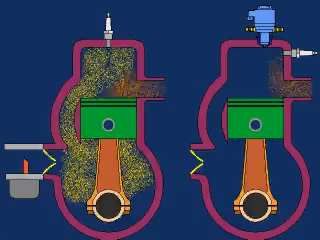
Direct Fuel Injection System in Gasoline Engine - A Review

fuel injections available. Fuel injection system has proven to
be an effective and durable strategy for controlling emissions
and reducing fuel consumption from gasoline-fuelled engines.
Fuel injection system is a promising technology that enhances
positively the fuel economy, engine performances and
emission reduction as compared to the conventional
carburettor system. Currently, motorcycles using carburettor
system are widely used as a mean of transportation especially
in urban areas. This conventional fuelling system produces
more harmful emissions and consumes more fuel compared to
the fuel injection system. It is therefore desirable to have a
fuel injection system that can easily be retrofitted to the
current on-road motorcycles.
C. Direct Injection
Fuel is injected directly into the main combustion area. The
engines would have either one main combustion chamber or a                            Fig. 1.2 Direct fuel Injection System
divided combustion chamber made up of a primary and
secondary chamber. Direct fuel injection reduces                        D. Gasoline Direct Injection (GDI)
hydrocarbon emission with proper design of the injection                In internal combustion engines, gasoline direct injection
timing and the positioning of the injector. The overall gas             (GDI) sometimes known as Fuel Stratified Injection (FSI) is
flow in the two-stroke engine has a significant effect on the           an increasingly popular type of fuel injection system
motion and evaporation of the fuel spraying process. The                employed in modern four and two-stroke petrol engines. The
fuel injection system for conventional spark ignition engines           petrol/gasoline is highly pressurized and injected by high
injects the fuel into the engine intake system. The advantages          voltage driven injectors via a common rail fuel line directly
of port fuel injection are increased power and torque through           into the combustion chamber of each cylinder as opposed to
improved volumetric efficiency and more uniform fuel                    conventional single or multi-point fuel injection that happens
distribution, more rapid engine response to changes in throttle         in the intake manifold tract or cylinder port. In some
position and more precise control of the equivalence ratio              applications gasoline direct injection enables stratified fuel
during cold-start and engine warm-up. Fuel injection allow              charge (ultra lean burn) combustion for improved fuel
the amount of fuel injected per cycle for each cylinder to be           efficiency and reduced emission levels at low load. The major
varied in response to input derived from sensors which define           advantages of a GDI engine are lower emission levels,
actual engine operating conditions. Two basic approaches                increased fuel efficiency and higher engine power output. In
have been developed but the major difference between the                addition the cooling effect of the injected fuel and the more
two is the method used to determine the air flow rate. It is            evenly dispersed combustion mixtures and temperatures
reported that parameters such as fluid flow pattern, injector           allow for improved ignition timing settings which are an
location, injection timings and injection pressure effectively          equally important system requirement. Emissions levels can
influence the droplet vaporization process and spatial vapour           be more accurately controlled with the GDI system. The
distribution in the cylinder. Fuel droplet after injection have         lower levels are achieved by the precise control over the
definite amount of kinetic energy based on their mass and               amount of fuel, air and ignition settings which are varied
velocity which is truly function of pressure difference in the          according to the engine load conditions and ambient air
rail and in the cylinder. The air in the chamber during                 temperature. In addition there are no throttling losses in some
compression process is in tumble motion which produces                  GDI designed engines as compared to a conventional fuel
deflection in the fuel spray. The addition air stream during the        injected or carbureted engine which greatly improves
injection process can force the fuel stream in the center of            efficiency and reduces pumping losses in engines without a
combustion area and enhances chances that fuel droplet do               throttle plate. Engine speed is controlled by the engine
not reach the cylinder and piston crown. The development of             management system which regulates fuel injection and
four-stroke spark-ignition engines that are designed to inject          ignition timing parameters instead of having a throttle plate
gasoline directly into the combustion chamber is an important           which restricts the incoming air supply. Adding this function
worldwide initiative of the automotive industry. The                    to the engine management system requires considerable
thermodynamic potential of such engines are significantly               enhancement of its processing and memory as direct injection
enhanced fuel economy, transient response and cold-start                plus other engine management systems must have very
hydrocarbon emission levels has led to a large number of                precise mapping for good performance and drivability. The
research and development projects that have the goal of                 engine management system continually chooses among three
understanding developing and optimizing gasoline                        combustion cycles: ultra lean burn, stoichiometric, and full
direct-injection (GDI) combustion systems.                              power output. Each cycle is characterized by the air-fuel ratio.
                                                                        The stoichiometric air-fuel ratio for petrol (gasoline) engines
                                                                        is 14.7:1 by weight, but the ultra lean cycle can involve ratios
                                                                        as high as 35:1 (or even higher in some engines for very
                                                                        limited periods). These mixtures are much leaner than in a
                                                                        conventional fuel injected engine and reduce fuel
                                                                        consumption and certain levels of

                                                                                      Published By:
                                                                   22                 Blue Eyes Intelligence Engineering
                                                                                      & Sciences Publication Pvt. Ltd.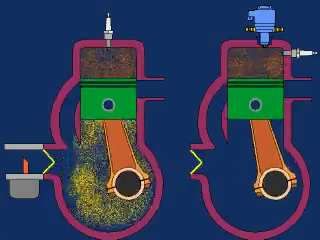
International Journal of Innovative Technology and Exploring Engineering (IJITEE)
ISSN: 2278-3075, Volume-4 Issue-4, September 2014
exhaust emissions considerably. Ultra lean burn cycle is used
for light-load running conditions, at constant or reducing road
speeds, where no acceleration is required. The fuel is not
injected at the intake stroke but rather at the latter stages of the
compression stroke so that the small amount of air-fuel
mixture is optimally placed near the spark plug. This stratified
charge is surrounded mostly by air which keeps the fuel and
the flame away from the cylinder walls for low emissions and
heat losses. The combustion of the fuel takes place in a radial
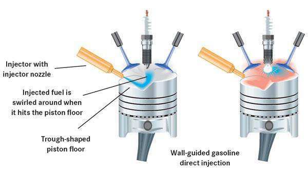
Transfer and Exhaust
(donut-shaped) cavity on the piston’s surface designed to
improve air swirl and delivered by a specially designed Fig. 1.3 Comparison of 2-Stroke
injector nozzle. This allows successful ignition without Carbureted SI Engine & Gasoline Direct Injection
misfire even when the air/fuel mixture is very lean. System
Stoichiometric cycle is used for moderate load conditions.
Fuel is injected during the intake stroke creating a II. LITERATURE REVIEW
homogenous fuel-air mixture in the cylinder. From the Hushim et al. [1] presented a review and comparative study
stoichiometric ratio an optimum burn results in a clean using 1-D simulation software - GT-Power on electronic fuel
exhaust emission further cleaned by the catalytic converter. injection (EFI) system between port-fuel injection (PFI) and
Full power cycle is used for rapid acceleration and heavy direct injection (GDI) system for retro fitment purpose of
loads (as when climbing a hill). The air-fuel mixture is small 125cc 4-stroke gasoline engine. From the study PFI
homogenous and the ratio is slightly richer than system was selected based on its high brake power, brake
stoichiometric which helps prevent knock (pinging). The fuel torque and brake mean effective pressure with low brake
is injected during the intake stroke. Direct injection is specific fuel consumption. Wislocki et al. [2] the injection
supported by other engine management systems such as duration in gasoline engines is similar (pressure values at
variable valve timing (VVT) with variable length intake present approx. 20 MPa) to the injection duration of diesel
manifold (VLIM) or acoustic controlled intake system fuel. The methodology and results of the tests related to the
(ACIS). A high performance exhaust gas recirculation valve fuel dose division and injection strategy on the
(EGR) is certainly required to reduce the high nitrogen oxides thermodynamic indexes during the combustion process were
(NOx) emissions that result from burning ultra lean mixtures. presented by them. The tests were performed for several ways
Conventional fuel injection engines could inject fuel of fuel dose division at injection pressures of 5, 10 and 20
throughout the 4 stroke sequence, as the injector injects fuel MPa (modifying also the time of the injection).They reported
onto the back of a closed valve. Earlier direct injection that the rate of pressure increment after the ignition is higher if
engines where the injector injects fuel directly into the there are more fuel injected before the ignition of the main
cylinder were limited to the induction stroke of the piston. As injection it also grows along the growth of the pressure of the
the RPM increases the time available to inject fuel decreases. injected fuel. The rate of heat release is proportional to the
Newer GDI systems have sufficient fuel pressure to inject cylinder pressure increment and depends on the same
more than once during a single cycle. Fuel injection takes relations. Sellnau et al. [3] developed a gasoline
place in two phases. During the intake stroke, some amount of compression-ignition combustion system for full-time
fuel is pre-injected into the combustion chamber which cools operation over the speed-load map. Low-temperature
the incoming air thus improving volumetric efficiency and combustion was achieved using multiple late injection (MLI),
ensuring an even fuel/air mixture within the combustion intake boost, and moderate EGR for high efficiency, low
chamber. Main injection takes place as the piston approaches NOx, and low particulate emissions. The relatively long
top dead centre on the compression stroke shortly before ignition delay and high volatility of RON 91 pump gasoline
ignition. combined with an advanced injection system and variable
valve actuation provided controlled mixture stratification for
low combustion noise. Tests were conducted on a single
cylinder research engine. Design of experiments and response
surface models were used to evaluate injection strategies,
injector designs and various valve lift profiles across the
speed-load operating range. At light loads an exhaust
rebreathing strategy was used to promote auto ignition and
maintain exhaust temperatures. At medium loads a triple
Charge Transfer and Scavenging Crankcase Compression injection strategy produced the best results with high thermal
efficiency. Detailed heat release analysis indicated that heat
losses were significantly reduced. At higher loads a
late-intake-valve-closing strategy was used to reduce the
effective compression ratio. For all tests intake air
temperature was 50 0C. They reported that with multiple late
injections and low-to-moderate fuel pressure spray
Compression Power penetration was low, mixing was fast, and wall wetting was
Published By:
23 Blue Eyes Intelligence Engineering
& Sciences Publication Pvt. Ltd.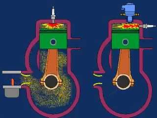
Direct Fuel Injection System in Gasoline Engine - A Review

avoided. Burke et al. [4] reported that gasoline direct                  magnetic charge from the magnet put into the fuel line gave a
injection provides reduced engine emissions, increased power             complete and clean burn so that power was increased with
and increased fuel economy as compared to port fuel injection            reduced operating expenses. The magnetic flux on the fuel
(PFI). Reduced emissions are largely due to starting the                 line dramatically reduced harmful exhaust emissions while
engine using high fuel pressure (up to 150 bar) and injecting            increasing mileage thereby saving money and improving
into the compression stroke. During a cold start fuel pressure           engine performance. It increased combustion efficiency and
must be increased from lift pump pressure (typically 4 to 6              provided higher-octane performance. The experimental
bar) to desired injection pressure (typically 25 bar minimum).           results show that the magnetic flux on fuel reduces the carbon
This study investigated the temperature and pressure effects             monoxide emission up to 13% for base engine, 23% in copper
during engine soak which allow vapor and air to form in the              coated (inside the cylinder head) engine and 29% in zirconia
fuel system. Vapor and/or air in the system caused a slower              coated (inside the cylinder head) engine. Non supercharged SI
fuel pressure build and increased start times. They concluded            engine using LPG with mixture formed by evaporated LPG
that by preventing air and vapor formation in the fuel system            has lower power output by about 8% as compared to original
start times were reduced and consistent. Gajbhiye et al. [5]             petrol engine. This disadvantage was eliminated by Mares et
developed an in-cylinder gasoline direct injection (GDI)                 al. [10] by using mixture formed by injection of liquid LPG.
engine incorporating novel combustion technologies which                 The thermodynamic analysis of the indicator diagram showed
consists of the upright straight ports to generate tumble                that the characteristic parameters of the cycle (including
motion, the electromagnetic swirl injector to realize                    parameters of the combustion course) stood practically
optimized spray dispersion and atomization and the compact               identical for operation on petrol and on LPG. The
piston cavity to maintain charge stratification. Zhao et al. [6]         experimental results showed that favorable operating
analyzed the processes of fuel injection, spray atomization              economy for car drive and positive ecological effects for
and vaporization, charge cooling, mixture preparation and the            environment. Kumarappa et al. [11] developed an electronic
control of in-cylinder air motion. The new technologies such             compressed natural gas (CNG) direct injection system to
as high-pressure, common-rail, gasoline injection systems and            eliminate the short circuiting losses in two stroke spark
swirl-atomizing gasoline fuel injectors were also discussed by           ignition engines to eliminate high exhaust emissions and
them. They concluded that technologies, along with computer              improve brake thermal efficiency during idling and at part
control capabilities have enabled the current new examination            load operating conditions. The fuel and time maps were
of an old objective that is the direct-injection,                        generated for the various operating conditions of the engine.
stratified-charge (DISC), gasoline engine. Ayaz et al. [7]               For the mapping the visualization tool was used to estimate
used the concept of making hole in transfer port by direct               the fuel injection time and fuel quantity for required running
injection of air stream in two stroke single cylinder SI engine          conditions of the engine. Experiments were carried out at the
for eliminating the drawbacks of poor scavenging and                     constant speed of 3500 rpm with a compression ratio of 12:1.
relatively high emissions. The variation of BSFC, NOx,                   The performance and emission characteristics of direct CNG
smoke and particulate emission with brake power were                     injection system and carburetted engine were described. The
studied for both scavenging and without scavenging and                   above studies indicate the improvement in brake thermal
results of work showed an improvement in the performance                 efficiency from 15.2% to 24.3%. This was mainly due to
and emissions characteristics of engine with scavenging. This            significant reduction in short circuit loss of fresh charge and
was reported as comparative analysis of experimental                     precise control of air fuel ratio. The pollution levels of HC
investigations carried out on a single cylinder, 2 strokes S.I.          and CO were reduced by 79.3% and 94.5% respectively
Engine with carburetor and with and without scavenging.                  compared to a conventional carburetted engine. Anand et al.
Loganathan et al. [8] developed and tested an electronically             [12] characterized PFI injectors which are suitable for small
fuel injection system on a 2 stroke SI engine at Indian institute        engines to study the effect of pressure on various spray
of Technology, Madras. The system was fitted on the intake               parameters. Two plate-type PFI injectors were studied: one
manifold of a single cylinder; air cooled 2 stroke scooter               with two orifices and the other with four orifices. The nozzle
engines. Tests were conducted at 3000 rpm and 4000 rpm at                orifice sizes were determined by microscopy. The fuel
different throttle position. The optimum injector pulse widths           quantity injected at pressures of 200 kPa, 500 kPa and 800
for thermal efficiency, lowest HC emissions and highest                  kPa were measured by collecting the fuel for injection pulses
power were all different. The maximum brake thermal                      of different durations. The spray structure of the PFI sprays
efficiency value were 22.6% and 23% at 3000 and 4000 rpm                 was determined by shadowgraphy. A single pulsed Nd:YAG
respectively. At a power output of 3kW and 1000 rpm the                  laser in conjunction with fluorescent diffuser optics was used
brake thermal efficiency was about 21% for the carbureted                as the light source for shadowgraphy. Backlit images of the
engine. It increased to 23% with the fuel injection system. HC           spray were obtained at various times after the start of injection
emissions were considerably lower than the carbureted                    using a CCD camera. This was done for sprays at different
version at all operating condition and speeds. The engine                pressures and different pulse durations. The spray angle and
could work with leaner mixtures with the injection system in             spray tip penetration were determined from the processed
general as compared to the carburetor. The maximum power                 shadowgraphy images. The backlit images also showed
increased with the injection system. The developed system                insights into the development of the spray. It was observed
could be used for mapping the engine for the development of              that coalescence occurs with liquid from the orifices merging
software for injection system control. Govindasamy et al. [9]            early on to form a single core. Tan et al. [13] investigated
investigated the performance and emissions of a 2 stroke SI              LPG direct injection from the transfer port of a
engine fitted with a fuel injection system. The use of strong            loop-scavenged two stroke engine. The injector nozzle was

                                                                                        Published By:
                                                                    24                  Blue Eyes Intelligence Engineering
                                                                                        & Sciences Publication Pvt. Ltd.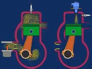
International Journal of Innovative Technology and Exploring Engineering (IJITEE)
                                                                     ISSN: 2278-3075, Volume-4 Issue-4, September 2014

placed in an area where it could inject through the transfer             consumption and engine-out emissions. The tuned exhaust
port window directly into combustion chamber with minimal                system was found to improve fuel economy of the engine by
fuel spillage into the port and minimal loss of fuel to the              12%. The major engine-out emissions HC and CO were
exhaust port. Several portions and orientations were                     reduced by a minimum of 27.8% and 10.7% respectively. An
simulated to determine the best injector nozzle location and             improved power output of 15.8% increase was achieved also
orientation. The simulation results indicated that high fuel             exhaust noise was reduced. Fathi et al. [19] studied the effect
trapping efficiency was possible with the proper location of             of the initial charge temperature on the second law terms
the injector and injection timing. Experimental results showed           under the various injection timings in a direct injection spark
an 80% reduction in exhaust emissions with the transfer port             ignition hydrogen fuelled engine during compression,
mounted injector nozzle compared to the baseline carbureted              combustion and expansion processes of the engine cycle. The
engine. Marouf et al. [14] performed the experimental                    first law analysis was done by using the results of a three
investigations on a single cylinder two stroke spark ignition            dimensional CFD code. The results showed a good agreement
engine in the carburetor and gasoline direct injection (GDI)             with the experimental data. Also for the second law analysis a
modes. The experiments were conducted on the engine in the               developed in- house computational code was applied. The
carburetor mode up to 80% throttle opening and for different             results revealed that the indicated work availability is more
combinations of speed and load. The engine was modified and              affected by varying hydrogen injection timing in comparison
fitted with an in-cylinder injector in the head. Fuel was                with other second law terms. Also increasing the initial charge
supplied through injector with the help of a high pressure DC            temperature caused the heat loss availability and exhaust gas
pump. Experiments for varying speed and load were                        availability to be increased and indicated work availability,
conducted under in-cylinder injection mode up to 80%                     combustion irreversibility and entropy generation were found
throttle opening. They reported that there is a significant              to be decreased. Salah [20] conducted the experiments to
reduction in BSFC, unburnt HC and CO emissions. Also the                 determine the effect of fuel-injection timings on engine
power output of the engine had shown an improvement.                     characteristics and emissions of a DI engine fueled with
Hiltner [15] determined the impact of fuel injection timing              NG-hydrogen blends (0%, 3%, 5% and 8%) at various engine
in-cylinder fuel distribution. Equivalence ratio maps were               speeds. Three injection timings namely 120°, 180° and 300°
acquired by Planar Laser Induced Fluorescence in an optical              CA BTDC with a wide open throttle at relative air–fuel ratio
engine with a production cylinder head. Experimental results             as 1.0 were selected. The ignition advance angle was fixed at
were used to determine the injection timing which produced               30° CA BTDC while the injection pressure was fixed at
the most uniform fuel distribution for the given engine. Cornel          1.4 MPa for all the cases. The tests were firstly performed at
[16] presented a concept based on the ram tuned injection.               low engine speed of 2000 rpm to determine the engine
The engine results showed that the engine torque remains in              characteristics and emissions. The results showed that the
all of the speed range at least at the same level as for the base        engine performance         (Brake Torque, Brake Power and
engines equipped with carburetors while the bsfc decreased               BMEP), the cylinder pressure and the heat release have the
generally by 35-45%. But the most important result was the               highest values at the injection timing of 180° CA BTDC,
reduction of pollution with 80-94% for the HC emissions and              followed by the 300° CA BTDC and the 120° CA BTDC. The
90% for the CO emissions respectively. Johnson[17]                       NOx emission was found to be highest at the injection timing
described the development and demonstration of an electronic             of 180° CA BTDC. The THC and CO emissions were found
direct fuel injection (EDFI) solution which was applicable to            to decrease while the CO2 emission increased with the
low cost and high production volume engines in several                   advancement in the injection timing. The addition of a small
industries. The system was based on the accumulator fuel                 amount of hydrogen to the natural gas was found to increase
injection operating principle which involved pressurizing fuel           the engine performance enhance combustion and reduce
within an injection nozzle and subsequently releasing the                emissions for any selected injection timings. Secondly the
pressurized fuel into the combustion chamber on command.                 tests were carried out at variable engine speeds (i.e.
This concept provided very short injection duration                      2000 rpm–4000 rpm) in order to further investigate the
throughout the dynamic operating range of the engine as well             engine performance. The injection timings of 180° and 300°
as high injection frequency capability. Obodeh et al. [18]               CA BTDC with CNG–H2 blends were only selected for
described the basic exhaust tuning mechanisms with respect               comparisons. The injection timing of the 300° CA BTDC was
to a two-stroke single-cylinder engine. Tuned adjustable                 reported to yield better engine performance as compared to
exhaust pipe for use on two-stroke motorcycle was designed               the 180° CA BTDC injection timing after a cutoff engine
and tested. The dynamometer used incorporated a flywheel of              speed of approximately 2500 rpm. Alimin et al [21]
appropriate moment of inertia to simulate the mass of the                developed a retrofit fuel injection kit to address such
motorcycle and rider. The test procedure involved                        challenges of meeting power requirement as a small cubic
measurement of the flywheel speed during an acceleration                 capacity prime mover and also in complying with the
phase resulting from opening the throttle. Calculation of the            emissions regulations currently put in place. The
instantaneous flywheel acceleration gave a measure of the                experimental works on the proposed fuel injection retrofit kit
torque and power characteristics. The airflow based values of            was initiated by preparing a dedicated engine test rig
delivery ratio, trapping efficiency and charging efficiency              equipped with the necessary instrumentation which allowed
were evaluated from the fuel flow values and the Spindt                  analysis on the engine operating performance. Among the
computation of the exhaust gas analysis. Experimental test               parameters investigated were engine torque, brake power,
results were presented for power output, specific fuel                   specific fuel consumption and engine thermal efficiency.

                                                                                       Published By:
                                                                    25                 Blue Eyes Intelligence Engineering
                                                                                       & Sciences Publication Pvt. Ltd.
Direct Fuel Injection System in Gasoline Engine - A Review

Throughout the work, other key operating parameters that                combustion chamber with single-hole pintle nozzle which the
were monitored the emissions levels of the exhaust gas and              conditions were similar to real DI engine conditions. The
operating consistency and durability. They concluded that the           results showed that with increase in cylinder air pressure from
developed prototype is able to work effectively in providing            10 to 25 the ignition delay and Combustion duration decrease
efficient fuel supply to power the small gasoline fuelled               for diesel and gasoline. And the duration of injection
engine. Karthikeyan et al. [22] designed and developed a                gradually decreases for diesel and gasoline irrespective
electronic fuel injection kit for a small capacity engine to run        injection pressure of 100 bar for gasoline with increase in
it at various speeds (in the range of 1000 to 5000 rpm) and at          cylinder air pressure. Also minimum values of ignition delay,
no load. They reported on design, development and                       burn duration and injection duration were observed at the fuel
fabrication of a new and compact port fuel injection (PFI)              injection pressure of 300 bar for both fuel at varying cylinder
system that could replace an in-used carburetor easily with             air pressure. It was also found that the combustion duration
minimum modifications. Mitianiec et al. [23] presented a                increases with increase in ignition delay for both fuels, due to
modified air-assisted direct fuel injection in a two-stroke             more time to mix the fuel and air. And combustion duration
engine, which changes propagation of fuel jet in the                    increases with increase in duration of injection for diesel. But
combustion chamber. The main problem of mixture formation               that increases until approximately 61 ms of injection duration
is short time for fuel evaporation after injection which should         and then decreases for gasoline. Archer et al. [27] developed
begin after closing of the exhaust port. The study showed               air-assisted Synerject Direct Injection (aSDI) for 2-stroke
interaction between the scavenged air, additional air stream            engines and the other Synerject electronic Port Injection
and fuel jet from the injector located in the cylinder head can         (SePI) for 4-stroke engines. Both systems are intended for
induce the small size of fuel droplets and fast evaporation.            application on small vehicles fitted with small 1 – 2 cylinder
The computational results of fuel mixture formation and                 gasoline engines of displacement 50 – 250 cm3 per cylinder.
combustion process in direct fuel injection two-stroke engine           Typical examples of such small vehicles are ATV’s (All
Robin EC-12 with capacity 115 cm3 were also presented.                  Terrain Vehicles), auto-rickshaws, motorcycles, motor
Sanjaikumar et al. [24] designed a prototype kit for use in             scooters and mopeds. They reported that significant reduction
retrofitting existing carbureted two-stroke engines to direct           in small vehicle fuel consumption & emission are available,
injection. The kit was designed for use on a TVS 50 a                   through application of the recently introduced air-assisted
motorcycle from the INDIA that is commonly used as a                    synerject direct injection system to 2-stroke engine &
transportation. The conventional fuel injection system kit              synerject electronic port injection system to 4-stroke engines.
incorporates the Orbital air blast direct injection system. This        Hunicz et al. [28] used direct injection contolled auto-ignition
injectionsystem was implemented in TVS 50. The design                   (CAI) single-cylinder research engine for gasoline
involved replacing the existing cylinder head with                      combustion. CAI operation was achieved with use of the
onedesigned to incorporate the direct injection valves as well          negative valve overlap (NAV) technique and internal exhaust
as a modified combustion chamber. An external compressor                gas re-circulation (EGR). Experiments were performed at
was added to supply compressed air to the system. The                   single injection and split injection, where some amount of fuel
carburetor was refined with a throttle body. They reported              was injected close to top dead centre (TDC) during NVO
that 88% reduction in hydrocarbon emissions and a 72%                   interval, and the second injection was applied with variable
reduction in carbon monoxide emissions versus the baseline              timing. Application of split injection showed benefits as
engine, while at the same time virtually eliminating visible            regard to single injection. Use of different fuel mass split ratio
smoke. The central fuel injection(CFI) system also showed a             and variable second injection timing resulted in optimization
32% increase in fuel economy, and had similar to better                 of mixture formation. At equal share of the fuel mass injected
performance than the carbureted engine. The central fuel                in the first injection during negative valve overlap (NVO) and
injection (CFI) system also showed improved cranking and                in the second injection in the beginning of compression the
idling characteristics over the carbureted engine. Junpei et al.        lowest emission level and cycle variability improvement were
[25] tested newly developed reverse- uniflow type 2-stroke              observed.
direct injection gasoline engine that was designed by
numerical simulations. They reported that in comparison with                                  III. CONCLUSION
the base engine, HC emission was decreased by up to 80%,                The following conclusions are drawn from the present review:
and BSFC was reduced by around 40%.Power and BSFC                       • The development in electronic fuel injection system has
were superior to that of a latest 4-stroke engine. Also the                 made it possible to overcome the level of pollution and
effects of the start of injection timing and the fuel spray                 improve the performance of engine in term of parameters
amount on the diffusion of fuel were examined by                            like fuel consumption. It has eliminated the short
performance tests and numerical simulations and the process                 circuiting losses completely.
was found important to improve the engine performance.                  • The fuel consumption and emission in two stroke SI
Ghadikolaei [26] investigate the effect of cylinder air pressure            engine can be reduced by optimizing the parameters like
and fuel injection pressure on combustion characteristics of                air-fuel ratio, bore-stroke ratio, delivery ratio and
direct injection (DI) diesel engine. The combustion                         processes like combustion and scavenging energy in
characteristics in this experimental study were measured in                 combustion chamber.
terms of ignition delay, combustion duration and injection              • The optimization of injection timing greatly reduces the
duration at varying cylinder air pressure (10-15-20 and 25                  specific fuel consumption and exhaust emission due to
bar) and fuel injection pressure (100-200 and 300 bar) based                better control over the air fuel ratio.
on diesel and gasoline. The tests were performed in a constant

                                                                                       Published By:
                                                                   26                  Blue Eyes Intelligence Engineering
                                                                                       & Sciences Publication Pvt. Ltd.
International Journal of Innovative Technology and Exploring Engineering (IJITEE)
ISSN: 2278-3075, Volume-4 Issue-4, September 2014
• The use of injector, fuel pump, crank angle encoder and [12] T.N.C. Anand, A.M. Mohan, D. Deshmukh and R. Rayavarapu.
“Optical characterization of PFI gasoline sprays: Effect of injection
ECU with various series can replace the carburettor and
pressure”, SAE Technical Paper, pp. 32-67, 2010.
its various disadvantages. [13] Y. Tan, H. Gitano and M. Khalil. “Development of a transfer port
• The use of DI system can improve atomization which injection system for two-stroke engines”, SAE Technical Paper , pp.
leads to proper burning of fuel and have less pollution 32-115,2012.
[14] W. M. Marouf, M. Md. and P. Saad. “Investigations on two Stroke
and better efficiency. Cycle Spark Ignition Engine Using Gasoline Direct Injection”, Energy
and Power, Vol. 2, No.7, pp. 116-122, 2012.
IV. FUTURE SCOPE [15] J. Hiltner. “The Impact of Injection Timing on In-Cylinder Fuel
Distribution in a Natural Gas Powered Engine”, SAE Technical Paper,
The development of direct injection system in petrol engine is 1997 [1997-05-01, Paper 971708].
beneficial in numerous fields like agricultural, heavy duty [16] S. Cornel. “Development of a Direct Injection Concept for Two
works and applications where the operating conditions vary Wheelers Equipped with Two Stroke Engines”, SAE Technical Paper,
with load. The scarcity of fossil fuels has urged the use of 1999 [1999-03-01, Paper 1999-01-1248].
[17] W. P. Johnson. “Electronic Direct Fuel Injection (EDFI) for Small
alternative fuels which are less costly and less harmful to the
Two-Stroke Engines”, SAE Technical Paper, 1999 [1999-09-28, Paper
environment. As biofuels are eco-friendly their use in direct 1999-01-3312].
injection engines can lead to additional advantages in the time [18] O. Obodeh and A. D. Ogbor. “Improving the performance of two
of high price of petroleum based fuels. The biofuels like strokeMotorcycle with tuned adjustable Exhaust pipe”, Research
Journal of Applied Sciences, Engineering and Technology, Vol. 1, No.
ethanol, methanol, butanol and their blends with petrol can be
2, pp. 59-65, 2009.
successfully used in direct injection engines. With the use of [19] V. Fathi, A. Nemati, S.H. Khalilarya and S. Jafarmadar “The effect of
biofuels in direct injection engines the pollution can be the initial charge temperature under various injection timings on the
reduced and efficiency can be increased. The existing two second law terms in a direct injection SI hydrogen engine”,
International Journal of Hydrogen Energy, Vol. 36, pp. 9252-9259,
stroke engines in market can be redesigned with direct fuel
2011.
injection system instead of existing carburetor system. This is [20] M.E. Salah. “The effects of fuel-injection timing at medium injection
going to replace the carburetor with combination of injector, pressure on the engine characteristics & emissions of a CNG-DI engine
fuel pump, crank angle encoder and electronic control unit fueled by a small amount of hydrogen in CNG”, International Journal
beside with various sensors. of Hydrogen Energy, Vol. 36, pp. 11997-12006, 2011.
[21] A.J. Alimin, M.F. Ali, M.F. Mohd Ali, M.F. Mohideen Batcha, S. Md
Seri and H. Selamat, “Experimental Study On The Application Of Fuel
REFERENCES Injection Retrofitment Kit For A Small Gasoline Fuelled Engine”,
[1] M. F. Hushim, A. J. Alimin, H. Selamat, and Mohd T. Muslim “PFI Environmental Science and Technology Conference
System for Retrofitting Small 4-Stroke Gasoline (ESTEC2009),Kuala Terengganu Malaysia, 2009.
Engines”,International Journal of Environmental Science and [22] G.Karthikeyan, M.Ramajayam and A.Pannirselvam “Design and
Development, Vol. 4, No. 4, pp. 375-378, 2013. Fabrication of an Electronic Fuel Injection Kit for a Conventional
[2] K. Wislocki, I. Pielecha, D. Maslennikov and J. Czajka Small Capacity SI Engine”,International Journal of Engineering and
“Thermodynamic Aspects of CombustionIn Gasoline Engines Fitted Advanced Technology (IJEAT) ISSN: 2249 – 8958, Vol.2, Issue-4,
with a Multiple Fuel Injection”,Journal of KONES Power train and 2013.
Transport, Vol. 18, No. 4, pp.543-553, 2011. [23] W. Mitianiec and M. Forma “Analysis of Direct Fuel Injectionin a
[3] M.C. Sellnau, J. Sinnamon, K. Hoyer and H. Husted “Full-Time Small Power Two-Stroke Engine”, Journal of KONES Powertrain and
Gasoline Direct-Injection Compression Ignition (GDCI) for High Transport, Vol. 16, No. 2 ,2009.
Efficiency and Low NOx and PM”, SAE International journal , Vol.5, [24] P.Sanjaikumar, K.Ashok kumar, S.Tamilselvan and M.Surya
No. 2, 2012. “Conventional Fuel Injection System in Two-Stroke
[4] D. Burke, D. Foti, J. Haller and W. J. Fedor “Fuel Rail Pressure Rise Engines”,International Journal of Engineering Trends and Technology
during Cold Start of aGasoline Direct Injection Engine”, SAE (IJETT) , Vol.4 , Issue 4, 2013.
International Journal, doi:10.4271/2012-01-039, 2012. [25] K. Junpeiand M. Yasuo “ Performance Tests of Reverse-Uniflow
[5] P. K. Gajbhiye and S. P. Chincholka “A Review on Electronically Type 2-stroke Direct Injection Gasoline Engine”, World Automotive
Assisted Gasoline Direct Injection 4-Stroke Single Cylinder Engine Congress Spain, 2004 .
System”,International Journal of Science and Research (IJSR),Vol. 2, [26] M. A. Ghadikolaei “Effect of Cylinder Air Pressure and Fuel Injection
No. 6, 2013. Pressure on CombustionCharacteristics of Direct Injection (DI) Diesel
[6] F. Zhao , M.C. Lai, and D.L. Harrington “Automotive spark-ignited Engine Fueled with Diesel and Gasoline”,International Journal of
direct-injection gasoline engines”,Elsevier,Vol. 25, Issue Application or Innovation in Engineering & Management (IJAIEM),
5,pp.437–562,1999. . Vol. 3, Issue 1, 2014.
[7] A.M. Ayaz, P.V. Pawar, P. Dahule and S. Papinwar, “Experimental [27] M. Archer and G. Bell “Advanced Electronic Fuel Injection Systems
Investigation of Direct Air Injection Scavenged Two Stroke –An Emissions Solution for both 2- and 4-stroke Small Vehicle
Engine”,(ISCCC 2009), Singapore Proc. of CSIT IACSIT Press, Vol.1, Engines”, SIAT26, pp.1-22, 2001.
2011. [28] J. Hunicz and P. Kordos “ An Experiment study of Fuel Injection
[8] M. Loganathan, P.V. Manivannan and A. Ramesh. “Investigation on strategies in CAI Gasoline Engine”, Experimental Thermal and Fluid
Performance and emissions of a 2 stroke SI engine fitted with a fuel Science , Elsevier, vol.35, pp.243-252, 2011.
injection system”, Indian Journal of Engineering & Material Science, [29] G. O. Young, “Synthetic structure of industrial plastics (Book style
Vol. 13, pp. 95-102, 2006. with paper title and editor),” in Plastics, 2nd ed. vol. 3, J. Peters,
[9] P. Govindasamy and S. Dhandapani. “Experimental investigation of Ed. New York: McGraw-Hill, 1964, pp. 15–64.
cyclic variation of combustion parameter in catalytically activated and [30] W.-K. Chen, Linear Networks and Systems (Book style). Belmont,
magnetically energized 2 stroke SI engines”, Journal of Energy & CA: Wadsworth, 1993, pp. 123–135.
Environment, Vol. 6, pp. 45-59, 2007 [31] H. Poor, An Introduction to Signal Detection and Estimation. New
[10] J. Mares, S. Beroun, J. Blazek and R. Holubec. “Automotive SIengine York: Springer-Verlag, 1985, ch. 4.
with injection of the liquid LPG into the inlet manifold”, 2007 [32] B. Smith, “An approach to graphs of linear forms (Unpublished work
[11] S. Kumarappa and G.P. Prabhukumar. “Improving the performance of style),” unpublished.
two stroke spark Ignition engine by direct electronic CNG injection”, [33] E. H. Miller, “A note on reflector arrays (Periodical style—Accepted
Jordan Journal of Mechanical and Industrial Engineering, Vol. 2, pp. for publication),” IEEE Trans. Antennas Propagat., to be published.
169-174, 2008. [34] J. Wang, “Fundamentals of erbium-doped fiber amplifiers arrays
(Periodical style—Submitted for
Published By:
27 Blue Eyes Intelligence Engineering
& Sciences Publication Pvt. Ltd.Direct Fuel Injection System in Gasoline Engine - A Review
publication),” IEEE J. Quantum Electron., submitted for publication.
[35] C. J. Kaufman, Rocky Mountain Research Lab., Boulder, CO, private
communication, May 1995.
[36] Y. Yorozu, M. Hirano, K. Oka, and Y. Tagawa, “Electron spectroscopy
studies on magneto-optical media and plastic substrate
interfaces(Translation Journals style),” IEEE Transl. J. Magn.Jpn.,
vol. 2, Aug. 1987, pp. 740–741 [Dig. 9th Annu. Conf. Magnetics Japan,
1982, p. 301].
[37] M. Young, The Techincal Writers Handbook. Mill Valley, CA:
University Science, 1989.
[38] (Basic Book/Monograph Online Sources) J. K. Author. (year, month,
day). Title (edition) [Type of medium]. Volume(issue). Available:
http://www.(URL)
[39] J. Jones. (1991, May 10). Networks (2nd ed.) [Online]. Available:
http://www.atm.com
[40] (Journal Online Sources style) K. Author. (year, month). Title. Journal
[Type of medium]. Volume(issue), paging if given. Available:
http://www.(URL)
[41] R. J. Vidmar. (1992, August). On the use of atmospheric plasmas as
electromagnetic reflectors. IEEE Trans. Plasma Sci. [Online]. 21(3).
pp. 876—880. Available:
http://www.halcyon.com/pub/journals/21ps03-vidmar
Published By:
28 Blue Eyes Intelligence Engineering
& Sciences Publication Pvt. Ltd.You can also read