Dialogic Brooktrout Fax Products - SDK 6.5 Linux End User Guide
←
→
Page content transcription
If your browser does not render page correctly, please read the page content below
Dialogic® Brooktrout® Fax Products
Linux End User Guide

SDK 6.5

January 2012       931-140-11

               www.dialogic.com
Copyright and Legal Notice
Copyright ©1998-2012 Dialogic Inc. All Rights Reserved. You may not reproduce this document in whole or in part
without permission in writing from Dialogic Inc. at the address provided below.
All contents of this document are furnished for informational use only and are subject to change without notice and do
not represent a commitment on the part of Dialogic Inc. and its affiliates or subsidiaries ("Dialogic"). Reasonable effort is
made to ensure the accuracy of the information contained in the document. However, Dialogic does not warrant the
accuracy of this information and cannot accept responsibility for errors, inaccuracies or omissions that may be contained
in this document.
INFORMATION IN THIS DOCUMENT IS PROVIDED IN CONNECTION WITH DIALOGIC® PRODUCTS. NO
LICENSE, EXPRESS OR IMPLIED, BY ESTOPPEL OR OTHERWISE, TO ANY INTELLECTUAL PROPERTY
RIGHTS IS GRANTED BY THIS DOCUMENT. EXCEPT AS PROVIDED IN A SIGNED AGREEMENT BETWEEN
YOU AND DIALOGIC, DIALOGIC ASSUMES NO LIABILITY WHATSOEVER, AND DIALOGIC DISCLAIMS ANY
EXPRESS OR IMPLIED WARRANTY, RELATING TO SALE AND/OR USE OF DIALOGIC PRODUCTS INCLUDING
LIABILITY OR WARRANTIES RELATING TO FITNESS FOR A PARTICULAR PURPOSE, MERCHANTABILITY, OR
INFRINGEMENT OF ANY INTELLECTUAL PROPERTY RIGHT OF A THIRD PARTY.
Dialogic products are not intended for use in certain safety-affecting situations. Please see
http://www.dialogic.com/company/terms-of-use.aspx for more details.
Due to differing national regulations and approval requirements, certain Dialogic products may be suitable for use only
in specific countries, and thus may not function properly in other countries. You are responsible for ensuring that your
use of such products occurs only in the countries where such use is suitable. For information on specific products, contact
Dialogic Inc. at the address indicated below or on the web at www.dialogic.com.
It is possible that the use or implementation of any one of the concepts, applications, or ideas described in this document,
in marketing collateral produced by or on web pages maintained by Dialogic may infringe one or more patents or other
intellectual property rights owned by third parties. Dialogic does not provide any intellectual property licenses with the
sale of Dialogic products other than a license to use such product in accordance with intellectual property owned or
validly licensed by Dialogic and no such licenses are provided except pursuant to a signed agreement with Dialogic. More
detailed information about such intellectual property is available from Dialogic's legal department at 1504 McCarthy
Boulevard, Milpitas, CA 95035-7405 USA. Dialogic encourages all users of its products to procure all necessary
intellectual property licenses required to implement any concepts or applications and does not condone or encourage any
intellectual property infringement and disclaims any responsibility related thereto. These intellectual property licenses
may differ from country to country and it is the responsibility of those who develop the concepts or applications to be
aware of and comply with different national license requirements.
Dialogic, Dialogic Pro, Dialogic Blue, Veraz, Brooktrout, Diva, Diva ISDN, Making Innovation Thrive, Video is the New
Voice, VisionVideo, Diastar, Cantata, TruFax, SwitchKit, SnowShore, Eicon, Eiconcard, NMS Communications, NMS
(stylized), SIPcontrol, Exnet, EXS, Vision, PowerMedia, PacketMedia, BorderNet, inCloud9, I-Gate, ControlSwitch,
NaturalAccess, NaturalCallControl, NaturalConference, NaturalFax and Shiva, among others as well as related logos,
are either registered trademarks or trademarks of Dialogic Inc. and its affiliates or subsidiaries. Dialogic's trademarks
may be used publicly only with permission from Dialogic. Such permission may only be granted by Dialogic's legal
department at 1504 McCarthy Boulevard, Milpitas, CA 95035-7405 USA. Any authorized use of Dialogic's trademarks
will be subject to full respect of the trademark guidelines published by Dialogic from time to time and any use of
Dialogic's trademarks requires proper acknowledgement.
The names of actual companies and products mentioned herein are the trademarks of their respective owners.
page 2Hardware Limited Warranty
Warranty for Hardware Products: Dialogic Corporation or its subsidiary that originally sold the hardware product
("Dialogic") warrants to the original purchaser of this hardware product, that at the time of delivery the hardware product
supplied hereunder will be free from defects in material and workmanship. This warranty is for the standard period set
out on Dialogic's website at http://www.dialogic.com/warranties and is void if the defect has resulted from accident,
misuse, abuse or misapplication. Any hardware product which becomes defective during the warranty period and is
returned by the original purchaser to Dialogic's Authorized Service Center with a Return Material Authorization (RMA)
number (which must be obtained from Dialogic before any return) within thirty (30) days after discovery of the defect with
a written description of the defect will be repaired or replaced at Dialogic's option. Freight charges will be paid by Dialogic
only for shipment back to you.
Additional Exclusions: Dialogic will have no obligation to make repairs or replacements necessitated by your fault or
negligence, improper or unauthorized use of the product, repairs or modifications made without Dialogic's prior written
approval or by causes beyond the control of Dialogic, including, but not limited to, power or air conditioning failure, acts
of God, improper interface with other units, or malfunction of any equipment or software used with the Dialogic product(s).
If Dialogic is requested and agrees to make repairs or replacements necessitated by any such causes, you will pay for such
service or replacement at Dialogic's then prevailing rates.
No Other Warranties: DIALOGIC DISCLAIMS AND YOU WAIVE ALL OTHER WARRANTIES, EITHER EXPRESS
OR IMPLIED, INCLUDING BUT NOT LIMITED TO IMPLIED WARRANTIES OF MERCHANTABILITY,
NON-INFRINGEMENT AND FITNESS FOR A PARTICULAR PURPOSE AND ANY WARRANTY AGAINST LATENT
DEFECTS, WITH RESPECT TO ANY DIALOGIC PRODUCT.
No Liability for Damages: IN NO EVENT SHALL DIALOGIC OR ITS SUPPLIERS BE LIABLE FOR ANY DAMAGES
WHATSOEVER (INCLUDING, WITHOUT LIMITATION, DAMAGES FOR LOSS OF PROFITS, INTERRUPTION OF
ACTIVITIES, LOSS OF INFORMATION OR OTHER PECUNIARY LOSS AND DIRECT OR INDIRECT,
CONSEQUENTIAL, INCIDENTAL, ECONOMIC OR PUNITIVE DAMAGES) ARISING OUT OF THE USE OF OR
INABILITY TO USE ANY DIALOGIC PRODUCT.
Limitation of Liability: DIALOGIC'S MAXIMUM CUMULATIVE LIABILITY SHALL BE LIMITED TO THE
AMOUNTS ACTUALLY PAID BY YOU TO DIALOGIC FOR THE SPECIFIC PRODUCT BEING THE OBJECT OF THE
CLAIM. YOU RELEASE DIALOGIC FROM ALL AMOUNTS IN EXCESS OF THE LIMITATION. YOU
ACKNOWLEDGE THAT THIS CONDITION IS ESSENTIAL AND THAT DIALOGIC WOULD NOT SUPPLY TO YOU
IF IT WERE NOT INCLUDED.
page 3Contents
About this Publication - - - - - - - - - - - - - - - - - - - - - - - - - - - - - - - - - 7
Introduction . . . . . . . . . . . . . . . . . . . . . . . . . . . . . . . . . . . . . . . . . . . . . . . . . . . . . . . . . . . . . . .7
Manual Conventions . . . . . . . . . . . . . . . . . . . . . . . . . . . . . . . . . . . . . . . . . . . . . . . . . . . . . . . 9
Related Documents . . . . . . . . . . . . . . . . . . . . . . . . . . . . . . . . . . . . . . . . . . . . . . . . . . . . . 9
Telephony Requirements . . . . . . . . . . . . . . . . . . . . . . . . . . . . . . . . . . . . . . . . . . . . . . . . 10
Terminology . . . . . . . . . . . . . . . . . . . . . . . . . . . . . . . . . . . . . . . . . . . . . . . . . . . . . . . . . . . . . 11
Updated Terminology . . . . . . . . . . . . . . . . . . . . . . . . . . . . . . . . . . . . . . . . . . . . . . . . . . 11
Dialogic® Brooktrout® TR1034 Fax Board Terminology . . . . . . . . . . . . . . . . . . . . . . . . 12
Related Documents . . . . . . . . . . . . . . . . . . . . . . . . . . . . . . . . . . . . . . . . . . . . . . . . . . . . . . . 13
Getting Technical Support . . . . . . . . . . . . . . . . . . . . . . . . . . . . . . . . . . . . . . . . . . . . . . . . . . 14
Chapter 1 – Getting Started . . . . . . . . . . . . . . . . . . . . . . . . . . . . . . . 15
Fax Board and Virtual Modules (SR140) . . . . . . . . . . . . . . . . . . . . . . . . . . . . . . . . . . . . . . . 16
SR140 Product Family . . . . . . . . . . . . . . . . . . . . . . . . . . . . . . . . . . . . . . . . . . . . . . . . . . . . . 17
Feature Pack Licenses . . . . . . . . . . . . . . . . . . . . . . . . . . . . . . . . . . . . . . . . . . . . . . . . . 18
Upgrade Licenses . . . . . . . . . . . . . . . . . . . . . . . . . . . . . . . . . . . . . . . . . . . . . . . . . . . . . 19
Demonstration Licenses . . . . . . . . . . . . . . . . . . . . . . . . . . . . . . . . . . . . . . . . . . . . . . . . 20
Software Licenses . . . . . . . . . . . . . . . . . . . . . . . . . . . . . . . . . . . . . . . . . . . . . . . . . . . . . 20
Product Activation . . . . . . . . . . . . . . . . . . . . . . . . . . . . . . . . . . . . . . . . . . . . . . . . . . . . . 21
Configuration . . . . . . . . . . . . . . . . . . . . . . . . . . . . . . . . . . . . . . . . . . . . . . . . . . . . . . . . . 21
Getting it Working . . . . . . . . . . . . . . . . . . . . . . . . . . . . . . . . . . . . . . . . . . . . . . . . . . . . . 22
Before Installing . . . . . . . . . . . . . . . . . . . . . . . . . . . . . . . . . . . . . . . . . . . . . . . . . . . . . . . 22
January 2012 4Chapter 2 – Installing TR1034 and TruFax® Hardware . . . . . . . . . 23
Installation Overview . . . . . . . . . . . . . . . . . . . . . . . . . . . . . . . . . . . . . . . . . . . . . . . . . . . . . . 24
Installing Your Board . . . . . . . . . . . . . . . . . . . . . . . . . . . . . . . . . . . . . . . . . . . . . . . . . . . . . . 25
Chapter 3 – Activating Dialogic® Brooktrout® SR140 Fax Software . .
26
Preparing for Activation . . . . . . . . . . . . . . . . . . . . . . . . . . . . . . . . . . . . . . . . . . . . . . . . . . . . 28
Displaying Node IDs . . . . . . . . . . . . . . . . . . . . . . . . . . . . . . . . . . . . . . . . . . . . . . . . . . . 28
Methods to Activate a License . . . . . . . . . . . . . . . . . . . . . . . . . . . . . . . . . . . . . . . . . . . . 28
Activating a License Using the Web . . . . . . . . . . . . . . . . . . . . . . . . . . . . . . . . . . . . . . . . . . . 30
Activating a License Using Email or Fax . . . . . . . . . . . . . . . . . . . . . . . . . . . . . . . . . . . . . . . 34
Installing Licenses . . . . . . . . . . . . . . . . . . . . . . . . . . . . . . . . . . . . . . . . . . . . . . . . . . . . . . . . 36
Managing License Files . . . . . . . . . . . . . . . . . . . . . . . . . . . . . . . . . . . . . . . . . . . . . . . . . . . . 37
Naming License Files . . . . . . . . . . . . . . . . . . . . . . . . . . . . . . . . . . . . . . . . . . . . . . . . . . 37
Backing Up Licenses . . . . . . . . . . . . . . . . . . . . . . . . . . . . . . . . . . . . . . . . . . . . . . . . . . . 37
Removing Licenses . . . . . . . . . . . . . . . . . . . . . . . . . . . . . . . . . . . . . . . . . . . . . . . . . . . . 38
Replacing Lost or Unrecoverable Licenses . . . . . . . . . . . . . . . . . . . . . . . . . . . . . . . . . . 38
Re-Installing Your Product . . . . . . . . . . . . . . . . . . . . . . . . . . . . . . . . . . . . . . . . . . . . . . . 38
Restoring License Files . . . . . . . . . . . . . . . . . . . . . . . . . . . . . . . . . . . . . . . . . . . . . . . . . 39
Re-Hosting License Files . . . . . . . . . . . . . . . . . . . . . . . . . . . . . . . . . . . . . . . . . . . . . . . 42
Chapter 4 – Configuring Dialogic® Brooktrout® SR140 Fax Software
and Dialogic® TR1034 Series/TruFax® Boards . . . . . . . 47
User-Defined Configuration File . . . . . . . . . . . . . . . . . . . . . . . . . . . . . . . . . . . . . . . . . . . . . . 48
Call Control Configuration File . . . . . . . . . . . . . . . . . . . . . . . . . . . . . . . . . . . . . . . . . . . . . . . 50
Global . . . . . . . . . . . . . . . . . . . . . . . . . . . . . . . . . . . . . . . . . . . . . . . . . . . . . . . . . . . . . . 50
Module . . . . . . . . . . . . . . . . . . . . . . . . . . . . . . . . . . . . . . . . . . . . . . . . . . . . . . . . . . . . . . 51
Global Module Parameters . . . . . . . . . . . . . . . . . . . . . . . . . . . . . . . . . . . . . . . . . . . . . . 52
Clock Module Parameters . . . . . . . . . . . . . . . . . . . . . . . . . . . . . . . . . . . . . . . . . . . . . . . 54
Ethernet Module Parameters . . . . . . . . . . . . . . . . . . . . . . . . . . . . . . . . . . . . . . . . . . . . . 55
Host Call Control Module Parameters . . . . . . . . . . . . . . . . . . . . . . . . . . . . . . . . . . . . . . 59
Port Module Parameters . . . . . . . . . . . . . . . . . . . . . . . . . . . . . . . . . . . . . . . . . . . . . . . . 60
Host Module . . . . . . . . . . . . . . . . . . . . . . . . . . . . . . . . . . . . . . . . . . . . . . . . . . . . . . . . . 62
Example of Call Control Configuration Files (callctrl.cfg) . . . . . . . . . . . . . . . . . . . . . . . . 77
January 2012 5Chapter 5 – Testing Dialogic® Brooktrout® SR140 Software and
TR1034/TruFax® Boards . . . . . . . . . . . . . . . . . . . . . . . . . . 79
modinfo . . . . . . . . . . . . . . . . . . . . . . . . . . . . . . . . . . . . . . . . . . . . . . . . . . . . . . . . . . . . . 80
feature . . . . . . . . . . . . . . . . . . . . . . . . . . . . . . . . . . . . . . . . . . . . . . . . . . . . . . . . . . . . . . 81
tfax . . . . . . . . . . . . . . . . . . . . . . . . . . . . . . . . . . . . . . . . . . . . . . . . . . . . . . . . . . . . . . . . . 82
Chapter 6 – Dialogic® Brooktrout® SR140 Software and
TR1034/TruFax® Specifications . . . . . . . . . . . . . . . . . . . . 84
Fax . . . . . . . . . . . . . . . . . . . . . . . . . . . . . . . . . . . . . . . . . . . . . . . . . . . . . . . . . . . . . . . . . 84
RTP . . . . . . . . . . . . . . . . . . . . . . . . . . . . . . . . . . . . . . . . . . . . . . . . . . . . . . . . . . . . . . . . 85
Voice . . . . . . . . . . . . . . . . . . . . . . . . . . . . . . . . . . . . . . . . . . . . . . . . . . . . . . . . . . . . . . . 85
Signal Generation/Detection . . . . . . . . . . . . . . . . . . . . . . . . . . . . . . . . . . . . . . . . . . . . . 85
System Requirements . . . . . . . . . . . . . . . . . . . . . . . . . . . . . . . . . . . . . . . . . . . . . . . . . . 85
Supported and Tested Devices for Interoperability . . . . . . . . . . . . . . . . . . . . . . . . . . . . 85
Telephony Requirements . . . . . . . . . . . . . . . . . . . . . . . . . . . . . . . . . . . . . . . . . . . . . . . 86
Supported Operating Systems . . . . . . . . . . . . . . . . . . . . . . . . . . . . . . . . . . . . . . . . . . . 86
Application Programming Interface . . . . . . . . . . . . . . . . . . . . . . . . . . . . . . . . . . . . . . . . 86
January 2012 6About this Publication
Introduction
This Dialogic® Brooktrout® Fax Products Linux End User Guide is
for users running either of the following in a
Linux environment:
Dialogic® Brooktrout® Fax SR140 Software
Dialogic® Brooktrout® TR1034 Series and Dialogic®
Brooktrout® TruFax® boards.
Refer to the Dialogic® Brooktrout® Fax Products Windows® End
User Guide if you operate in a Windows® environment
This document contains the following chapters:
Chapter 1 explains how you get started installing and
configuring Dialogic® Brooktrout® software and hardware in a
Windows® environment.
Chapter 2 explains how to install your Dialogic® Brooktrout®
TR1034 Series and Dialogic® Brooktrout® TruFax® boards.
Chapter 3 describes how to activate Dialogic® Brooktrout®
SR140 Fax Software.
Chapter 4 describes how to configure the Dialogic® Brooktrout®
Fax Software with Dialogic® Brooktrout® SR140 Software and
TR1034/TruFax boards.
Chapter 5 explains testing the Dialogic® Brooktrout® SR140
Fax Software and Dialogic® Brooktrout® TR1034/TruFax®
boards.
January 2012 7 Chapter 6 provides specifications for Dialogic® Brooktrout®
SR140 Fax Software and Dialogic® Brooktrout®
TR1034/TruFax® boards..
January 2012 8Manual Conventions
Manual Conventions
This manual uses the following conventions:
Italics denote the names of variables in the prototype of a
function, and file names, directory names, and program names
within the general text.
The Courier font in bold indicates a command sequence entered
by the user at the system prompt, for example:
cd /usr/sys/brooktrout/boston/bfv.api
The Courier font not bolded indicates system output, for
example:
C:>Files installed.
The Courier font also denotes programming code, such as C and
C++. Programming code appears in program examples.
Bold indicates the data type of the prototype of a function,
Bfv API functions, dialog boxes, dialog box controls, windows,
and menu items.
Square brackets [ ] indicate that the information to be typed is
optional.
Angle brackets < > indicate that you must supply a value with the
parameter.
.
The Caution icon is used to indicate an action that could cause harm to
the software or hardware.
The Warning icon is used to indicate an action that could cause harm to
the user.
Related Documents
For product information, white papers, FAQs, and more, access the
Dialogic web site at www.dialogic.com.
January 2012 9Manual Conventions
Telephony Requirements
Physical Media Call Control
Ethernet 10/100 T.38 v0 or v3 H.323
RTP V2 G.711 SIP
January 2012 10Terminology
Terminology
Updated Terminology
The current version of this document includes terminology that
differs from previous versions. Please note the changes below:
Former Terminology Replaced with...
Host-based fax Dialogic® Brooktrout® SR140 Fax Software
Virtual modules or
Virtual boards Brooktrout SR140 Fax Software
Software modules or
VoIP modules SR140 Software
SR140 virtual modules or
SR140
TR1000 Series SDK Dialogic® Brooktrout® SDK
TR1000 Series Product Dialogic® Brooktrout® Fax Board
TR1000 Series Module or
TR1000 Series Board Brooktrout fax board
or
board
Brooktrout System Software Dialogic® Brooktrout® Runtime Software
January 2012 11Terminology
Dialogic® Brooktrout® TR1034 Fax Board Terminology
The Dialogic® Brooktrout® TR1034 Fax Board is also referred to
herein by one or more of the following terms, or like terms including
“TR1034”:
Brooktrout TR1034 Fax Board
Brooktrout TR1034 Board
TR1034 Fax Board
TR1034 Board
TR1034
January 2012 12Related Documents
Related Documents
For product information, white papers, FAQs, and more, access the
Dialogic web site at www.dialogic.com.
January 2012 13Getting Technical Support
Getting Technical Support
Dialogic provides technical services and support for purchasers of
our Dialogic® Pro service contracts.
If you purchased a support contract from a reseller, please contact
the reseller for technical support.
To obtain technical support, please use the following web site:
www.dialogic.com/support/
January 2012 141 - Getting Started
This chapter provides an introduction and quick start installation
instructions for installing the Dialogic® Brooktrout® software and
hardware in a Linux environment.
January 2012 15Fax Board and Virtual Modules (SR140)
Fax Board and Virtual Modules (SR140)
Dialogic’s intelligent fax board platform, the Dialogic® Brooktrout®
TR1034 Fax Board, provides Dialogic ISV (Integrated Software
Vendor) partner’s fax application with the capability to communicate
from their application to the telephone or IP network.
For software-only systems using IP only, Dialogic has implemented
the SR140 as a virtual module. Although it is software, the SR140
appears to the fax application just like a board. That helps simplify
your fax application publisher to provide a single product that works
for hardware and software.
January 2012 16SR140 Product Family
SR140 Product Family
There are two major SR140 products, the original full SR140 and the
SR140-L. Each product differs in the available functionality, with
the full SR140 having the highest functionality. The tables below
summarize the feature set available for the different SR140 products
over the course of their release history.
Note: Full SR140 and SR140-L licenses cannot co-exist in the same
system.
Table 1. Full SR140 Release History
Release Date Example Model Name Feature Set
R1 March 2008 SR140-4F T.38 V.17
Advanced Fax (Very High Res,
MMR, JBIG/Color pass-
through)
R2 February SR140-4F-V.34 T.38 V.34
2009
T.38 V.17
Advanced Fax (Very High Res,
MMR, JBIG/Color pass-
through
R3 April 2010 SR140-4-R3 G.711 RTP
IVR
T.38 V.34
T.38 V.17
Advanced Fax (Very High Res,
MMR, JBIG/Color pass-
through
January 2012 17SR140 Product Family
Table 2. SR140-L Release History
Release Date Example Model Name Feature Set
R1 April 2010 SR140-L-4-R1 Maximum eight channels per
system
T.38 V.17
Advanced Fax (Very High Res,
MMR, JBIG/Color pass-
through)
Feature Pack Licenses
Feature pack licenses are available to allow you to add features
matching a later release. The feature pack license is added to your
existing license to bring you up to the latest set of available features.
For example, if you currently own an original SR140 R1 (SR140-4F),
you can obtain an upgrade pack license (SR140-FeaturePack-4-R3)
that will add in the new features, without first requiring an R2
feature pack license.
January 2012 18SR140 Product Family
Upgrade Licenses
Upgrade licenses allow you to add the feature set of the full SR140 to
the SR140-L.
For example an SR140-L-2-R1 together with a SR140-L-UPGRADE-
SR140-2-R3 will have the same features as an SR140-2-R3.
January 2012 19SR140 Product Family
Demonstration Licenses
Demonstration licenses are available for both the SR140 and SR140-
L. Demonstration licenses will cause each transmitted or received
page to be overlaid with the word 'Demonstration'. Only one
demonstration license can be installed in a system at any time and
cannot be used together with non-demonstration licenses.
Demonstration licenses expire after some time period, typically 30
days from when the license was first activated. If a demonstration
license expires, it will cause the SR140 to stop functioning. You will
need to delete any demonstration licenses that have expired before
you can use a nondemonstration license..
Software Licenses
The SR140 is delivered inside your fax application. The SR140
license is the right to use the software products in an entitlement
purchased from Dialogic. The license is represented by the contents
of a License File that is used by the software to restrict use to that
entitlement. When you install the software, you acknowledge the
License Agreement that governs SR140 licensing.
January 2012 20SR140 Product Family
A License Key is delivered in paper form or electronic form and
shows you what your entitlement is and allows you to apply your
entitlement to a computer system when you install the SR140 Fax
Software.
Make sure to keep your License Key certificate in a safe place, where
you can find it easily.
Product Activation
As well as helping you stay within your entitlement, your SR140 Fax
Software product uses copy protection technology. Following
installation of the software, Product Activation is a process for tying
a license to a particular system, limiting use of that licensed
software to one computer system. Product Activation is simple and
may be completed via the Internet, email or by fax and involves
supplying your License Key shown on the License Key certificate and
a unique identifier of the computer system that can be used to lock a
license to a computer (known as node-locking).
Configuration
All modules - virtual modules or real boards - need to know how to
handle call control over the IP network. Once you have installed the
software and activated your product, you need to enter settings that
control how connections are made between the IP network and the
virtual module. This process is called configuration.
January 2012 21SR140 Product Family
Getting it Working
Before Installing
Things to know before you begin the installation
See Before Installing on page 22
Hardware Installation
See Installing TR1034 and TruFax® Hardware on page 23
Product Activation
See Activating Dialogic® Brooktrout® SR140 Fax Software on
page 26.
Configuration
See Configuring Dialogic® Brooktrout® SR140 Fax Software and
Dialogic® TR1034 Series/TruFax® Boards on page 47.
Test
See Testing Dialogic® Brooktrout® SR140 Software and
TR1034/TruFax® Boards on page 79.
Before Installing
When doing the installation, you need the following:
Root privileges for the server
and either of the following:
Enterprise Linux ES/AS 4.0
Enterprise Linux ES/AS 5.0
Enterprise Linux 6.0
Use the installation program provided with your application
software to install the software for the SR140.
January 2012 222 - Installing TR1034 and TruFax®
Hardware
This chapter applies to users of the Dialogic Brooktrout® TR1034
Series and Dialogic Brooktrout® TruFax® boards. This chapter does not
apply to users of the Dialogic Brooktrout SR140 Fax Software.
For detailed hardware installation instructions, see the hardware
installation card that came with your Brooktrout board.
January 2012 23Installation Overview
Installation Overview
This section describes how to install your fax board on a Linux
system.
Check your system to verify the minimum system requirements.
Install your Brooktrout System Software.
Install your fax board. Refer to Installing Your Board on page 25.
Configure your Brooktrout board. Refer to Configuring
Dialogic® Brooktrout® SR140 Fax Software and Dialogic®
TR1034 Series/TruFax® Boards on page 47
Verify the installation. Refer to Testing Dialogic® Brooktrout®
SR140 Software and TR1034/TruFax® Boards on page 79
January 2012 24Installing Your Board
Installing Your Board
Before installing your board, make sure you have assigned the board
a unique module number.
¾ Follow these instructions to install your Brooktrout board
into your computer:
1. Power off your PC and any peripheral equipment connected to it.
2. Unplug your PC power cord.
3. Remove the outside cover of your computer.
4. Open your computer and locate a free PCI slot in the computer
chassis.
5. Remove the slot cover.
6. Carefully align the Brooktrout board with the PCI slot and firmly
seat the board into the slot.
7. Tighten the mounting bracket screw to secure the board to the
chassis.
Warning: When installing the board, be sure that the mounting bracket is
securely fastened to the chassis and the chassis is plugged into a
grounded three prong plug. Improper chassis or bracket grounding can
result in harmful or fatal electrical shock as well as component damage.
8. Replace the outside cover of your computer.
9. Use the cable supplied with your board and connect one end of the
cable into the RJ-45 telephone connector on the board’s mounting
bracket.
10. Plug the other end of the cable into the connector for your
telephone service.
11. Reconnect your PC power cord, and power on your computer.
January 2012 253 - Activating Dialogic® Brooktrout®
SR140 Fax Software
This chapter describes how to activate a license for the Brooktrout
SR140.
The Brooktrout SR140 functionality is protected against piracy and
abuse by licensing technology that uses product activation. A
License Key is sold to the user who exchanges the key for a license
file during or after installing the software. The license file is tied to
the system during activation by imprinting a unique system
signature (a node ID) on the license file, and is based on the
machine's MAC address.
The License Key can either be a unique, paid-for license key that
provides a perpetual license or a demo license key that results in
software that provides limited support for a limited time. Both types
of product - licensed as demo or paid-for - require activation. You
have several ways to activate the product.
January 2012 26The licensing software also verifies the following:
The signature of the license is not broken.
The license is not expired.
The node ID of the license matches the node ID of the compute
(sometimes referred to as the “Node Lock” of the computer).
The system clock is not set back.
Please contact Dialogic Technical Support if you are unable to use
the license. See Getting Technical Support on page 14.
This document has the following sections:
Preparing for Activation on page 28.
Activating a License Using the Web on page 30.
Activating a License Using Email or Fax on page 34.
Installing Licenses on page 36.
Managing License Files on page 37.
January 2012 27Preparing for Activation
Preparing for Activation
Because Dialogic® Brooktrout® SR140 Fax Software is an IP-based
technology, Dialogic uses the IP network and the Internet to perform
Product Activation. Ideally, the system you are installing on should
be connected to an IP Network and to the Internet.
Archive the License Key Certificate and the License File once the
product has been activated.
Note: Because the license software verifies if the system clock has
been set back, you should ensure that the system date is set
correctly.
Displaying Node IDs
You can run the listnodeid utility to print out the node ID. You need
root privileges to run the utility.
The following is an example of the output:
$ listnodeid
ID value (vendor defined): UYPWK6XWO1BGEKODJO4MLQ
The following is the default installation location for the listnodeid:
/usr/sys/brooktrout/boston/fw
To execute the lisnodeid you have to enter the following:
./listnodeid
Methods to Activate a License
Using the interactive web method
Activates licenses using the Dialogic License Activation website.
After successfully processing activation information, you can
choose to download the file immediately or have the license
emailed to you. Within a couple of minutes Dialogic sends an
email containing a license file, if you select the email option. See
Activating a License Using the Web on page 30.
Create a request for email or fax
January 2012 28Preparing for Activation
See Activating a License Using Email or Fax on page 34. After
successfully processing activation information, Dialogic sends an
email containing a license file. Dialogic sends a license in about
one working day.
January 2012 29Activating a License Using the Web
Activating a License Using the Web
You can activate your Dialogic® Brooktrout® SR140 Fax Software
license on the web using a computer that has web access. This can be
a different computer than the server on which you are installing the
Brooktrout SR140.
It is critical that you enter the node ID information on the website without
errors. The software generates an unusable license when you enter
incorrect node ID information. The second attempt to obtain the license
using the corrected node ID information is considered a re-hosting. In this
case, you to refer to Re-Hosting License Files on page 42.
¾ Follow the steps below:
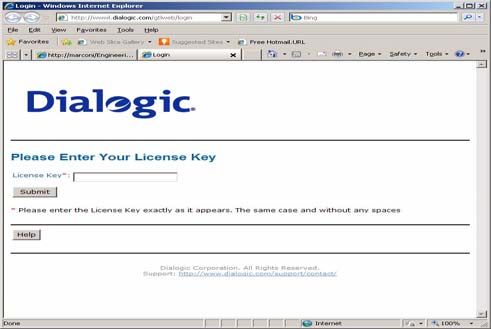
1. On a computer that has Internet Access, enter the web address
www.dialogic.com/activation, which directs you to a secure
server. The following screen appears.
2. Enter your original License Key (this can be found on your
License Key certificate) and click Submit. The following screen
appears.
January 2012 30Activating a License Using the Web
3. Click Generate Licenses. The following screen appears.
January 2012 31Activating a License Using the Web
4. Select the Product you are activating. Select the Node ID Type
and enter the Node ID.
5. Click Generate License.
6. Verify that the information on this screen is correct and click
Confirm. The following screen appears.
January 2012 32Activating a License Using the Web
7. Click Save to File or enter your email address and click Email to
have the License emailed to you.
8. Follow the instructions Installing Licenses on page 36 to install
the license file.
January 2012 33Activating a License Using Email or Fax
Activating a License Using Email or Fax
When your system cannot support the previous options (for example,
you have no Internet connections) you can activate your license by
sending the information to Dialogic using email or fax.
Note: If you activate your license by email or fax, Dialogic will send
you the license file in about one business day.
¾ To activate a Brooktrout license by Email or Fax, follow
the steps below:
1. Create a Software License Request text file with the following
information.
Node ID Type
Node ID
License Key
First Name
Last Name
Email
Phone
Company
Address
City
State
Zip
Country
Application
2. Email the saved file to activation@dialogic.com as an attachment,
or fax this information to +1 781-433-2350 at the Dialogic License
Activation Center for processing.
3. When you receive the license file from Dialogic, go to Installing
Licenses on page 36 to install it in the correct location. The
following is a sample Software License Request file that you can
use as a guide.
January 2012 34Activating a License Using Email or Fax
Figure 3-1 Sample Software License Request
Note: A special demonstration license is available in either a single-
or two-channel configuration that will run for a 30 day period.
Contact your Dialogic sales representative to obtain this
license.
Products with demonstration licenses run with limited
functionality. Please note that only one demonstration license
may be used at a time. Domonstration licenses have incoming
and outgoing fax pages overlaid with a Demonstration
watermark.
January 2012 35Installing Licenses
Installing Licenses
The following environment variable must be set to the directory
where the license files are located.
BRKTD_LICENSE_FILE
You can set the environment variable to point to any directory. Place
a copy of your license files in the directory that you have chosen. The
licensing software will automatically use the licenses when required.
January 2012 36Managing License Files
Managing License Files
The section contains the following instructions to manage the license
files:
Naming License Files on page 37
Backing Up Licenses on page 37
Removing Licenses on page 38
Replacing Lost or Unrecoverable Licenses on page 38
Re-Installing Your Product on page 38
Restoring License Files on page 39
Re-Hosting License Files on page 42
If you remove or add Ethernet network cards to your system, the license
files may become invalid. To activate the products, re-host the licenses
(see Re-Hosting License Files on page 42).
Naming License Files
All license files end with the .lic extension. One file can contain one
or more licenses. The license file name is usually in either form:
dd-mmm-yyyy.lic
dd-mmm-yyyy-x.lic (next available number)
However, the license file name can be any file name with a .lic
extension.
Backing Up Licenses
To back up licenses, copy all *.lic files from the directory into a safe
location. Copying the license files back to the same directory restores
the licenses.
The path to the directory containing the license files can be found in
the environment variable:
BRKTD_LICENSE_FILE
January 2012 37Managing License Files
Removing Licenses
To remove a license follow the steps below. (You need to know the
license serial number.)
1. You can find the path to .lic file in the environment variable:
BRKTD_LICENSE_FILE
2. Open each .lic file until you find the file that includes the one with
the serial number in it.
3. Delete the license containing that serial number.
If there are no more entries in the .lic file, you can delete the file.
Replacing Lost or Unrecoverable Licenses
When a license is lost or not recoverable, get a new copy by going
through the web activation process again. See Activating a License
Using the Web on page 30.
Re-Installing Your Product
If you want to simply re-install your product on the same computer
system after upgrading or replacing your hard disk or any other
upgrade that maintains the your network card’s MAC address, you
can use the same license file without having to re-activate your
product.
January 2012 38Managing License Files
Restoring License Files
If anything ever happens to your computer that leads to corruption of
your software and the License File, retrieving another copy is a
simple procedure. To retrieve another copy of your License File, follow
the steps below:
1. Visit the Dialogic activation website at:
www.dialogic.com/activation. The following screen appears.
January 2012 39Managing License Files
2. Enter your original License Key (this can be found on your
License Key certificate) and click Submit. The following screen
appears.
3. Click View Licenses. The following screen appears.
January 2012 40Managing License Files
4. In the Select Product window, select your product and then select
the appropriate Node ID. Click View. The following screen appears.
5. Click Save to File or enter your email address and click Email to
have the License emailed to you.
6. Follow the instructions Installing Licenses on page 36 to install
the license file.
January 2012 41Managing License Files
Re-Hosting License Files
To allow you to upgrade your computer to a new system or recover
from a network card failure, Dialogic allows you to “re-host” your
licensed software from one computer system to another. This process
involves returning your current license and receiving another one.
The activation center web site allows you to automatically re-host
your licensed software one time without technical support. For
subsequent re-hosts you will need to contact Dialogic Technical
Services and Support.
¾ Follow the steps below:
1. Visit the Dialogic activation website at:
www.dialogic.com/activation
The following screen appears.
2. Enter your original License Key (this can be found on your
License Key certificate) and click Submit. The following screen
appears
January 2012 42Managing License Files
3. Click Re-host Licenses. The following screen appears.
4. Select your product and click Return to return the license to
Dialogic. The following screen appears.
January 2012 43Managing License Files
5. Verify that the information on this screen is correct and click
Confirm. The following screen appears.
January 2012 44Managing License Files
6. In the Select Product box click the product for which you are re-
hosting. Select the Node ID Type and enter the Node ID. The
Node ID Type must be VID (Vendor Defined Node ID).
7. Click Generate License. The following screen appears.
January 2012 45Managing License Files
8. Click Confirm. The following license appears.
9. Click Save to File or enter your email address and click Email to
have the License emailed to you.
10. Follow the instructions Installing Licenses on page 36 to install
the license file.
January 2012 464 - Configuring Dialogic® Brooktrout®
SR140 Fax Software and Dialogic®
TR1034 Series/TruFax® Boards
This chapter describes how to configure the following products:
Dialogic® Brooktrout® SR140 Fax Software
Dialogic Brooktrout® TR1034 Series and Dialogic Brooktrout®
TruFax® boards
On Linux, Dialogic provides two text files to configure the Dialogic®
Brooktrout® Products:
User-Defined Configuration File (btcall.cfg)
Call Control Configuration File (callctrl.cfg)
However, this method has not been adapted by every ISV software
package. Instead, when this method is not used by your ISV
application, please skip this chapter and consult the documentation
that comes with your ISV application.
January 2012 47User-Defined Configuration File
User-Defined Configuration File
The user-defined configuration file is an ASCII file that contains
parameters that set values such as specific fax formatting. The Bfv
API supplies a default configuration file named btcall.cfg in the
app.src directory. The programs in app.src use btcall.cfg.
You can edit the btcall.cfg file with a standard text editor. Refer to
the Dialogic®Brooktrout®Bfv APIs Reference Manual for detailed
information.
The following are the bare minimum set of parameters that must be
set on your configuration file.
call_control /usr/sys/brooktrout/boston/config/callctrl.cfg
bt_cparm /usr/sys/brooktrout/boston/config/BT_CPARM.CFG
The parameters are described below:
Parameter Value
call_control Specifies the name of the call control configuration file to use. The
callctrl.cfg file replaces the teleph.cfg and ecc.cfg files.
Value Type: character string
Default: callctrl.cfg
January 2012 48User-Defined Configuration File
font_file Specifies the name of the file that contains the transmit/convert font
for ASCII. An optional font number, indicating the downloadable
font to use, can be specified (if no font number is specified, 0 is
assumed). The font file must be located in the current directory, or
the correct path must be included with its name. The file is opened,
and the contents downloaded to the module when BfvLineReset is
called using the mill_load_fonts option. Multiple occurrences of font
file parameters with different font numbers are permitted in the
configuration file.
When a font number that is specified for ASCII conversion has not
been downloaded, a default font is used. This is font 255. Font 255
may be specified using the font_file keyword. If not, it defaults to
ibmpcps.fz8 (no path). When font downloads are done as described
above, font 255 is always downloaded regardless of whether other
font numbers are listed using this keyword.
Some font numbers may be reserved for preloaded fonts. Range for
font number: 0 – 6,255
Value Type: character string; decimal can be included and is
optional
Default: ibmpcps.fz8 (no path) and 0
bt_cparm Specifies the path and name of the country telephony parameter file
to use.
Value Type: character string
Default: BT_CPARM.CFG
January 2012 49Call Control Configuration File
Call Control Configuration File
The call control configuration file is an ASCII file that contains
configuration parameters for all telephony modules. The call_control
parameter in the user-defined configuration file specifies the path
and file name of the call control configuration file (the Bfv API uses
callctrl.cfg as the default value). The callctrl.cfg file contains
configurations for ISDN layer 1 and layer 2 regardless of the selected
protocol.
You can edit the callctrl.cfg file with a standard text editor.
The following sections must be present in the call control
configuration file to configure your Dialogic®Brooktrout® Products.
Global
Module
Host Module
Refer to the Dialogic®Brooktrout® Bfv APIs Reference Manual for
detailed information about the configuration parameters. Sample
files to configure analog, BRI, DID, E1, T1, SIP, and H.323 are
located in the default installation directory
/usr/sys/brooktrout/config/samples.cfg.
Global
The following parameters affect operation of the entire call control
and enable tracing. Specify these parameters at the beginning of
your call control configuration file. Modified only under the direction
of Dialogic Technical Services and Support.
l3l4_trace=verbose
l4l3_trace=verbose
api_trace=verbose
internal_trace=verbose
host_module_trace=verbose
ip_stack_trace=verbose
trace_file=ecc.log
max_trace_files=1
max_trace_file_size=10
January 2012 50Call Control Configuration File
Module
Defines the configuration of each module. Create a set for each
TR1034, TruFax, and SR140 module installed in your system. If your
system contains more than 120 SR140 channel. Create one SR140
module for each set of 120 channels.
Each module may contain one or more of the following sections:
Global Module Parameters
Clock Module Parameters
Ethernet Module Parameters
Host Call Control Module Parameters
Port Module Parameters
January 2012 51Call Control Configuration File
Global Module Parameters
Set the following parameters to define configuration information
that applies to the whole module [module.#]. The # represent the
module id assigned to the hardware via the rotary switch. For SR140
number your modules starting at 41 hex.
The following are the bare minimum set of parameters that must be
set on your configuration file.
[module.2]
channels=30
vb_firm=\usr\sys\brooktrout\boston\fw\bostvb.so
These parameters are described below:
January 2012 52Call Control Configuration File
Parameter Value
channels Specifies the number of channels on either a hardware or virtual module
configured to receive a firmware download.
Note: This parameter only applies when using the Boston Host Service
(Bostsrv). If you use the service, you must start it before you start
any applications (see your installation and configuration guide for
instructions).
When the firmware is downloaded to a module for the first time, the
assigned ordinal channel numbers start wherever the assignment left
off on the previous module. As the system initializes the modules, this
numbering process creates a continuous ordering of the channel
assignments across all the modules in the system. On later downloads,
each module’s ordinals begin at the same location, regardless of any
decrease or increase in the channel count of a lower-numbered module.
Therefore, if you decrease the channel count for a lower numbered
module, the process creates gaps in the channel numbering
assignments, possibly affecting your application. If you attempt to
increase the channel count above any module’s initial channel count, the
system ignores the added channels.
For the following situations, restart the driver whenever you want to:
1. Get a continuous assignment of channel numbers after decreasing
the channel count on any module.
2. Increase the number of channels above a module’s initial channel
count.
Set this parameter as follows:
0 Specifies downloading the firmware to the default value of
the number of channels on the module.
1 – 1024 Specifies a value defining the number of channels on the
module configured to receive a firmware download.
Range: 1 – 1024 (not to exceed the maximum number of available
channels on the module).
Value Type: decimal
Default: 0
January 2012 53Call Control Configuration File
vb_firm Indicates that the module is a virtual module and specifies the file name
of the shared library that contains the loadable firmware for the virtual
module.
Note: This parameter only applies when using the Boston Host Service
(Bostsrv). If you use the service, you must start it before you start
any applications (see your installation and configuration guide for
instructions).
Default: No default. Absence of the parameter indicates that the
module is not a virtual module.
Clock Module Parameters
Set the following parameters to define configuration information
that applies to a module's clock [module.#/clock_config]. The #
represent the module id assigned to the hardware via the dip switch.
The SR140 does not require this section.
Note: Set only for TR1034 and TR1034-N (IP capable) models.
TR1034 non IP models and TruFax do not use these
configuration parameters.
The following are the bare minimum set of parameters that must be
set on your configuration file.
[module.2/clock_config]
clock_mode=master
clock_source=trunka
These parameters are described below:
Parameter Value
clock_mode Specifies a value that determines whether the module drives the clock
on the CT bus or receives its clocking from the CT bus. Set this
parameter to:
MASTER Configures the module to drive the clock on the
CT bus.
SLAVE Configures the module to receive clocking from the
CT bus.
Default: MASTER
January 2012 54Call Control Configuration File
clock_source Specifies the source of the clock used to drive the CT bus. Set this
parameter only if you set the value for clock_mode to master. The
module derives its clock from:
Internal The internal oscillator.
TrunkA The network trunk, port A.
TrunkB The network trunk, port B.
TrunkC The network trunk, port C.
TrunkD The network trunk, port D.
TrunkE The network trunk, port E.
TrunkF The network trunk, port F.
TrunkG The network trunk, port G.
TrunkH The network trunk, port H.
Netref1 The H.100/H.110 network reference (1) clock.
Netref2 The H.100/H.110 network reference (2) clock.
clock_a The H.100/H.110 A clock.
clock_b The H.100/H.110 B clock.
Default: TrunkA
Note: If you configure a port as inactive and inadvertently select it as
the clock_source, the system cannot operate.
Ethernet Module Parameters
Set the following parameters to define configuration information
that applies to a module's ethernet port [module.#/ethernet.1]. The #
represent the module id assigned to the hardware via the dip switch.
For SR140 number your modules starting at 41 hex.
Note: Set only for SR140 and TR1034, TruFax does not use these
configuration parameters.
The following are the bare minimum set of parameters that must be
set on your configuration file.
SR140
[module.41/ethernet.1]
ip_preference=ipv4_only
ip_interface=eth0
ip_interfaceV6=
media_port_min=56000
January 2012 55Call Control Configuration File
media_port_max=56999
TR1034-N
[module.2/ethernet.1]
ip_address=0.0.0.0
ip_netmask=0.0.0.0
ip_gateway=0.0.0.0
ip_broadcast=0.0.0.0
media_port_min=56000
media_port_max=56999
The parameters are described below:
Parameter Value
ip_address Specifies the IP address of the module’s Ethernet interface. Set this
parameter only if you set the value in the dhcp parameter to DISABLED.
xxx.xxx.xxx.xxx Configures the Ethernet interface to use the
specified IP address.
Value Type: dotted decimal
Default: None
Note: The Dialogic® Brooktrout® module does not support the domain
naming system (DNS) data base. Your application has the
responsibility of converting domain names into resolved dotted-
decimal notation IP addresses.
ip_broadcast Specifies the IP broadcast address of the module’s Ethernet interface.
Set this parameter to:
xxx.xxx.xxx.xxx Configures the Ethernet interface to use the
specified broadcast address.
Value Type: dotted decimal
Default: None
ip_gateway Specifies the gateway address of the module’s Ethernet interface. Set
this parameter to:
xxx.xxx.xxx.xxx Configures the Ethernet interface to use the
specified gateway address.
Value Type: dotted decimal
Default: None
January 2012 56Call Control Configuration File
Parameter Value
ip_interface Specifies the identity of the device on the PC with the IP interface that
the virtual module can use for sending IP messages.
Note: This parameter applies only to the SR140.
Set the value of this parameter to the name of any device in the PC with
an IP interface. If you do not provide a value (blank string), the virtual
module chooses the first interface in the PC to send its messages.
Note: The format for the value provided by this parameter is operating
system dependent.
The Windows® format for the value provided in this parameter is:
The name of the IP device (Global Unique IDentifier (GUID)) followed
by
A colon (:) character followed by
The index number of the device’s IP address
For example:
{4D36E96E-E325-11CE-BFC1-08002BE10318}:0
The Linux format is the ethernet device name.
For example:
ip_interface=eth0
Value Type: character string (up to 256 characters)
Default: (the virtual module uses the first interface in
the PC for sending IP messages)
ip_netmask Specifies the netmask address of the module’s Ethernet interface. Set
this parameter only if you set the value in the dhcp parameter to
DISABLED.
xxx.xxx.xxx.xxx Configures the Ethernet interface to use the
specified netmask address.
Value Type: dotted decimal
Default: 0.0.0.0
January 2012 57Call Control Configuration File
Parameter Value
ip_preference Specifies the IP family preference that should be used by the virtual
module for sending IP messages.
The following are the allowable parameter values:
ipv4_only Only IPv4 supported
ipv6_only Only IPv6 supported
ipv4_preferred IPv4 and IPv6 both supported. For outbound
SIP calls, the specific IP family type used for the
IP messages sent by the virtual module will be
determined by the SIP Call Control stack.
ipv6_preferred IPv4 and IPv6 both supported. For outbound SIP
calls, the specific IP family type used for the
IP messages sent by the virtual module will
be determined by the SIP Call Control stack.
Value Type: character string
Default: ipv4_only
media_port_max Specifies the highest IP port number that the module can use. Set this
value to a value 1000 above the value specified for the media_port_min
parameter.
57000 Sets this value as the highest port number.
Range: 2024 – 65535
Value Type: decimal
Default: 57000
media_port_min Specifies the lowest IP port number that the module can use for media
transmissions. Set this value to a value 1000 below the value specified
for the media_port_max parameter.
56000 Sets this value as the lowest port number.
Range: 1024 – 64535
Value Type: decimal
Default: 56000
January 2012 58Call Control Configuration File
Host Call Control Module Parameters
Set the following parameters to configuration the module to use a
specific ip stack [module.#/host_cc.1]. The # represent the module id
assigned to the hardware via the dip switch. For SR140 number your
modules starting at 41 hex. Each IP stack is configured using a host
module [host_module.y].
Note: Set only for SR140 and TR1034, TruFax does not use these
configuration parameters.
The following are the bare minimum set of parameters that must be
set on your configuration file.
[module.41/host_cc.1]
host_module=1
number_of_channels=120
The parameters are described below:
Parameter Value
host_module Specifies the number that identifies the IP call control stack that the
module can use.
Set this parameter to match the host_module number identifier
associated with the third party IP call control stack the module can use.
Valid values are:
Range: 1–9
Value Type: decimal
Default: 1
number_of_channels Specifies the number of channels enabled to use the specified stack. This
number must not exceed the number of available channels on the
module.
The Bfv API allocates the first available channels on the module to this
stack. When the module can use multiple stacks, the Bfv API maps the
channels to the stacks in the order that the stacks appear in the
configuration file. If you configure a module to use telephony ports and
an IP call control stack, the Bfv API allocates channels to the telephony
interface first.
Range: 1 – 1024 (not to exceed the maximum number of available
channels on the module)
Value Type: decimal
Default: 1
January 2012 59Call Control Configuration File
Port Module Parameters
Set the following parameters to configure the module to use a
specific port type [module.#/port.y]. The # represent the module id
assigned to the hardware via the dip switch.
Note: Set only for TR1034 and TruFax. The SR140 does not use these
configuration parameters.
Specific the configuration parameters for the following protocols and
line interfaces:
Analog Direct Inward Dialing (DID)
Analog Loop Start
ISDN Basic Rate Interface (BRI)
E1 ISDN Primary Rate Interface (PRI)
E1 CAS
E1 CAS R2
E1 and T1 QSIG
T1 ISDN Primary Rate Interface (PRI)
T1 Robbed Bit Signaling (RBS)
Refer to the Dialogic®Brooktrout® Bfv APIs Reference Manual for
detailed information about the configuration parameters. Sample
files to configure the port are located in the default installation
directory /usr/sys/brooktrout/config/samples.cfg.
The following are the bare minimum set of parameters that must be
set on your configuration file.
[module.2/port.1]
port_config=T1_ROBBED_BIT
protocol_file=/usr/sys/brooktrout/boston/config/winkstart.lec
did_timeout=5
max_did_digits=0
num_rings=2
The parameters are described below:
January 2012 60Call Control Configuration File
Parameter Value
port_config Specifies one of the following values that defines the CT bus or line type
to configure for the port.
INACTIVE Disabled port
ANALOG Analog Loop Start line
ANALOG_DID Analog Direct Inward Dialing (DID) line
BRI Basic Rate Interface
E1_ISDN E1 ISDN
E1_CAS E1 CAS
E1_R2_CAS E1 CAS R2
E1_DPNSS E1 DPNSS (not supported in this release)
E1_QSIG E1 QSIG
T1_QSIG T1 QSIG
T1_ISDN T1 ISDN
T1_ROBBED_BIT T1 RBS
Default: INACTIVE
Note: Any port defined as INACTIVE completes configuration
requirements for the port. The configuration-specific parameters
do not apply to inactive or disabled ports.
protocol_file Specifies the full path and name of the protocol file to load for the E1
CAS port. Most of the time a path should be used for this file name. Set
this parameter to:
fxo_groundstart.lec
fxo_loopstart.lec
fxs_groundstart.lec
fxs_loopstart.lec
Default: fxs_loopstart.lec
did_timeout Specifies a value that defines the maximum timeout allowed before
processing the call after assuming receipt of the last DID digit. Set this
parameter to:
0 Indicates no waiting time.
1 – 20 Specifies the number of seconds to allow after receiving the
last DID digit before processing the call.
Unit: second
Range: 0 through 20
Default: 10 (used when the Bfv API does not find another value for
this parameter)
January 2012 61Call Control Configuration File
Parameter Value
max_did_digits Specifies a value that defines the maximum number of DID digits to
expect before accepting an incoming call. Set this parameter to:
0 Disables waiting for DID digits.
1 – 255 Specifies the number of digits to expect before accepting an
incoming call.
Range: 0 through 255
Default: 0
Note: The system can report all of the DID digits it received from the
network to the application even if the number of received DID
digits exceeds the number specified for max_did_digits. To remove
the excess digits, set the did_offset parameter so that the system
only passes the expected number of digits to the application.
num_rings Specifies a value that defines the number of rings the system must
detect before the system reports a new incoming call to the application.
Set this parameter to:
Range: 1 to 255
Default: 2
Note: In North America and some other locations, the system sends the
caller ID signal between the first and second rings. To detect the
caller ID correctly, you must set the num_rings parameter to a
value of 2 or greater to prevent the system from reporting the call
to the application before the caller ID has been sent by the Central
Office.
Host Module
Defines the configuration of each host module [host_module.y].
Create a host module for each IP stack installed your system; SIP or
H.323. The # represent the host module id starting at index 1.
Note: Set only for SR140 and TR1034-N (IP-capable) models.
TR1034 non-IP models and TruFax do not use these
configuration parameters.
Each host module may contain one or more of the following sections:
Global Host Module Parameters
Stack Host Module Parameters
T.38 Host Module Parameters
RTP Host Module Parameters
January 2012 62You can also read