SPIRIT 1.0 Evo User Manual - ePropulsion
←
→
Page content transcription
If your browser does not render page correctly, please read the page content below
SPIRIT 1.0 Evo User Manual
             Mar, 2021 Version 1.1
Copyright © 2021 ePropulsion. All Rights Reserved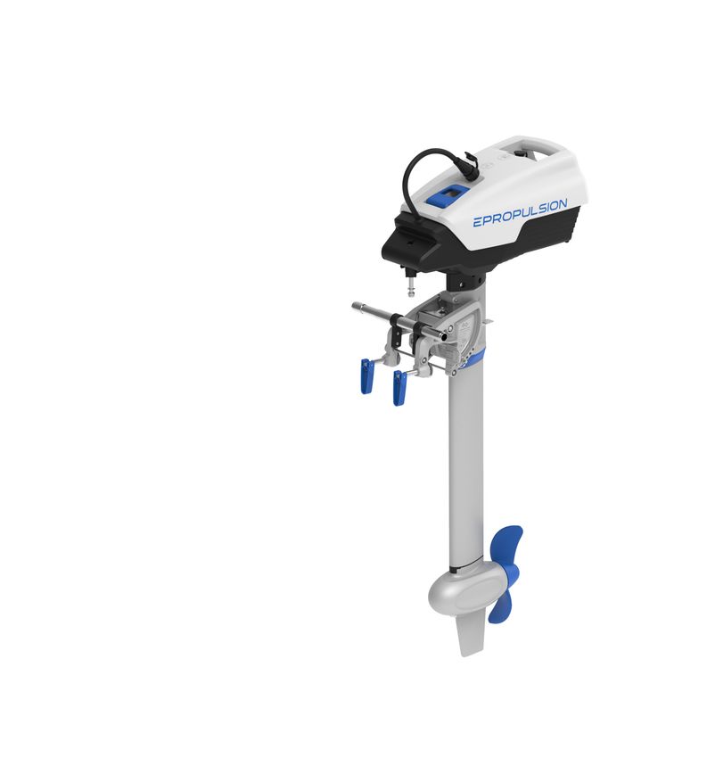
Acknowledgement
Thanks for choosing ePropulsion products, your trust and support in our company
are sincerely appreciated. We are dedicated to providing high-performance electric
outboards, electric outboards, sup/kayak motors, reliable lithium batteries and acces-
sories.
Welcome to visit www.epropulsion.com and contact us if you have any concerns.

Using This Manual
Before use of the product, please read this user manual thoroughly to understand the
correct and safe operations. By using this product, you hereby agree that you have
fully read and understood all contents of this manual. ePropulsion accepts no liability
for any damage or injury caused by operations that contradict this manual.

Due to ongoing optimization of our products, ePropulsion reserves the rights of con-
stantly adjusting the contents described in the manual. ePropulsion also reserves the
intellectual property rights and industrial property rights including copyrights, patents,
logos and designs, etc.

This manual is subject to update without prior notice, please visit our website www.
epropulsion.com for the latest version. If you find any discrepancy between your
products and this manual, or should you have any doubts concerning the product or
the manual, please visit www.epropulsion.com.

ePropulsion reserves the rights of final interpretation of this manual.

This manual is multilingual, in case of any discrepancy in the interpretation of differ-
ent language versions, the English version shall prevail.

Symbols
The following symbols will help to acquire some key information.

     Important instructions or warnings

     Useful information or tips

                                            1
Product Identification
Below picture indicates the serial numbers of SPIRIT 1.0 Evo. Please note the posi-
tion of the serial numbers and record them for access to warranty service and other
after-sale services.
Serial NO.
Electric Outboard
Motor
Electric Outboard Motor
Model:
Rated Power: 1000
W
Rated Voltage:
48 V
S/N:
Date:
Model:
Rated Power: 1000 W
Rated Voltage: 48 V
S/N:
Date:
Figure 0-1
2Table of Contents
Acknowledgement...................................................................................... 1
Using This Manual...................................................................................... 1
Symbols..................................................................................................... 1
Product Identification................................................................................. 2
1 Product Overview.................................................................................... 5
1.1 In the Package.......................................................................................... 5
1.2 Parts and Diagram................................................................................... 7
1.3 Specifications........................................................................................... 8
1.4 Declaration of Conformity...................................................................... 11
2 Important Notes before Start................................................................. 12
2.1 Outboard................................................................................................. 12
2.2 Battery..................................................................................................... 13
3 Installation............................................................................................ 15
4 Connecting 48V Battery......................................................................... 19
4.1 Selecting the Battery.............................................................................. 19
4.2 Connecting 48V Battery for Single Engine............................................ 19
4.3 Connecting 48V Battery for Twin Engine.............................................. 21
5 Operation.............................................................................................. 22
5.1 Checklist before Start............................................................................ 22
5.2 Starting.................................................................................................... 22
5.3 Stopping.................................................................................................. 24
5.4 Power off the External Battery............................................................... 25
5.5 Tiller Adjustment.................................................................................... 26
5.6 Tilting up the Outboard Motor............................................................... 28
5.7 Fixing the Steering Direction.................................................................. 29
5.8 Fixing for Easy Carrying......................................................................... 29
6 Evo Control System............................................................................... 30
6.1 Display Panel.......................................................................................... 30
6.2 Charging the Remote Control................................................................ 34
6.2.1 Charging by Solar Power.............................................................. 34
36.2.2 Charging by Wired Connection.................................................... 34
6.3 Power Adjusting..................................................................................... 36
6.3.1 Power Adjusting for Evo Control System.................................... 36
6.3.2 Recalibration................................................................................. 37
6.4 Use of Safety Wristband........................................................................ 39
6.4.1 Pairing Safety Wristband with Evo Control System.................... 39
6.4.2 Man Overboard Protection........................................................... 39
6.4.3 Emergency Stop............................................................................ 39
6.5 Pairing Evo Control System with the Outboard.................................... 40
6.6 Hydro Generation Function.................................................................... 42
6.7 Warning Messages................................................................................. 43
7 Battery Charging.................................................................................... 45
8 Trim Angle Adjusting............................................................................. 47
9 Anti-grounding Mode............................................................................. 49
10 Maintenance........................................................................................ 51
10.1 Notes..................................................................................................... 51
10.2 Propeller Maintenance......................................................................... 51
10.3 Replacing the Anode............................................................................ 52
10.4 Maintenance Time Table..................................................................... 54
11 Transportation and Storage................................................................. 55
11.1 Transportation...................................................................................... 55
11.2 Placement............................................................................................. 56
11.3 Storage.................................................................................................. 56
12 Emergency Situations.......................................................................... 57
12.1 Impact Damage.................................................................................... 57
12.2 Submerged Outboard........................................................................... 57
12.3 Low Battery Level................................................................................. 57
13 Warranty ............................................................................................. 58
13.1 Warranty Policies................................................................................. 58
13.2 Out of Warranty.................................................................................... 59
13.3 Warranty Claim Procedures................................................................. 59
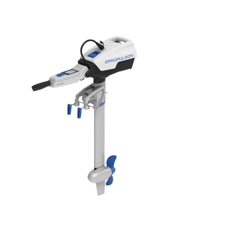
41 Product Overview
SPIRIT 1.0 Evo is designed to be an integrated electric outboard with high overall effi-
ciency and long cruising duration. The power of SPIRIT 1.0 Evo is equivalent to a 3hp
petrol outboard but works quieter. With removable tiller or remote control, it’s easy
to carry and store. All these high-performance features make SPIRIT 1.0 Evo an ideal
option for tenders, dinghies and sailboats.
The SPIRIT 1.0 Evo includes two models, SPIRIT 1.0 Evo-L and SPIRIT 1.0 Evo-S,
which have different shaft lengths for adaptation of different transom heights.
1.1 In the Package
Unpack the package and check if there is any damage caused during transport.
Check all the items inside the package against the below list. If there is any transport
damage or lack of any listed item, please contact your dealer immediately.
Items Qty./Unit Figure
Outboard
1 set
(Main part)
Battery
(Purchase 1 set
Separately)
5Items Qty./Unit Figure
Battery
1 set
Charger
Spirit External
Battery Cable
1 set
(Purchase
Separately)
Steering
2 pieces
Lock Pin
User Manual,
Warranty Warranty
Quality
Certificate
Card, Invitation Card
1 set
Quality Certifi-
cate & Invita-
tion Card
Save the ePropulsion original package for the outboard storage.
Other accessories mentioned in this user manual need to be purchased by users
from ePropulsion authorized dealers.
There are currently four types of official chargers for SPIRIT Battery Plus. The
one included in the package is Standard Charger. The other three are Fast Charg-
er, Solar Charger and DC Charger, which need to be purchased separately by us-
ers from ePropulsion authorized dealers.
61.2 Parts and Diagram
Battery Handle
Power Port
Charging Port
Power Cable Charging Indicator
Battery Lock
Battery Pack
(built-in Li-po
Handle Shaft batteries and BMS)
Trim Release Lever
Clamp Tightening
Handle
Bracket Clamp
Beaching Pin
Trim Pin
Shaft
Propeller
Motor
Skeg
Anode
Figure 1‑1
71.3 Specifications
SPIRIT 1.0 Evo-L / SPIRIT 1.0 Evo-S
Type Electric
Rated Input Power 1 kW
Rated Current 20.8 A
Comparable Petrol Outboard 3 hp
Maximum Overall Efficiency 55%
Maximum Rotation Speed 1200 rpm
Steering Remote Control / Tiller Control
10.2 kg (S)
Weight (without battery)
10.6 kg (L)
405 mm × 226 mm × 1072 mm (S)
Dimension (L×W×H)
405 mm × 226 mm × 1197 mm (L)
625 mm (S)
Shaft Length
750 mm (L)
Trim Angle 0°, 7°, 14°, 21°, 85°
Propeller (Diameter / Pitch) 280 mm / 5.8"
8SPIRIT Battery Plus
Type Lithium-Polymer
Rated Capacity 1276 Wh
Rated Voltage 45.6 V
Cut-off Voltage 33.6 V
Full Charged Voltage 52.2 V
Charging Time ~8 hrs
Cycle Life ≥500 cycles (80% of Rated Capacity)
Charging: 0°C ~ 45°C (32°F ~ 113°F)
Temperature Range
Discharging: -20°C ~ 60°C (-4°F ~ 140°F)
Dimension (L×W×H) 416 mm × 275 mm × 202 mm
Weight 8.8 kg / 19.4 lbs.
External Battery Requirement
Type Lead-acid Battery or Lithium Battery
Rated Voltage 48 V
Minimum Voltage 39 V
Maximum Voltage 60 V
Minimum Continuous
28 A
Discharge Current
Internal Resistance ﹤100 mΩ
9SPIRIT 1.0 Plus Charger
Output Power 180 W
Output Voltage 52.2 V DC
Output Current 3.5 A
Cut-off Current 0.4 A
Operation: -10°C ~ 45°C (14°F ~ 113°F)
Temperature Range
Storage: -30°C ~ 70°C (-22°F ~ 158°F)
Rated Input Voltage 100 ~ 264 V AC
Output Frequency 50 Hz / 60 Hz
Input Current (Max) 2 A @ 220 V
Efficiency ≥87%
It is forbidden to charge other batteries with SPIRIT charger. It is strictly forbid-
den to charge SPIRIT battery with non-official standard charger.
SPIRIT Battery Plus, SPIRIT 1.0 Evo machine and SPIRIT 1.0 Plus charger should
be used together. It is forbidden to use SPIRIT Battery Plus and SPIRIT 1.0 Plus
charger for SPIRIT 1.0 Evo machine, and it is forbidden to use SPIRIT battery for
SPIRIT 1.0 Evo machine. Otherwise, the consequences of mixed use are at your
charge.
101.4 Declaration of Conformity
Object of the Declaration:
Product: Electric Outboard Motor
Model: SPIRIT 1.0 Evo, SPIRIT 1.0 Evo-S, SPIRIT 1.0 Evo-L
Company Name: Guangdong ePropulsion Technology Limited
Address: Room 201, Bldg.17A, 4th XinZhu Road, SongShan Lake District, Dongguan
City, Guangdong Province, China
The object of the declaration is in conformity with the following directives:
EMC-directive 2014/30/EU
MD-directive 2006/42/EC
RED-directive 2014/53/EU
Applied Standards:
EN 55014-1:2017 EN 300328:2019
EN 55014-2:2015 EN 50663:2017
EN 61000-3-2:2014 EN 62368-1:2014+A1:2017
EN 61000-3-3:2013/A1:2019 EN 60204-1:2018
EN 301489-1:2019 EN ISO 12100:2010
EN 301489-3:2019
This device complies with part 15 of the FCC Rules: Operation is subject to the follow-
ing two conditions:
1. This device may not cause harmful interference and,
2. This device must accept any interference received, including interference that
may cause undesired operation.
Signature:
Shizheng Tao, Chief Executive Officer & Cofounder of
Guangdong ePropulsion Technology Limited
112 Important Notes before Start
The SPIRIT 1.0 Evo electric outboard motor is designed to offer clean propulsion and
excellent experience on water. For safety reasons, please read the following instruc-
tions and notes before using this product. By using this product you hereby: 1) agree
to these notes and instructions; 2) agree not to use this product for purposes that
infringe upon or contravene laws and regulations; 3) agree to be responsible for your
own conduct while operating this product.
2.1 Outboard
WARNING
• Only allow adults who have thorough understanding of this manual to operate
this product.
• Always have a paddle on board especially if the electric outboard motor is the
only propulsion system.
• Familiarize yourself with all the outboard operations, including start/stop,
steering and tilting.
• Check the status of the outboard and battery level before each trip.
• Follow the boat manufacturer’s instructions on the maximum allowed outboard
power of your boat, do not overload the boat or the outboard.
• Take serious of battery safety. Follow battery instructions, avoid short-circuit,
overheat, overcharge and over-discharge.
• Only run the outboard while the propeller is under water.
• Stop the outboard immediately if someone falls overboard.
• Do not leave the outboard in the water while the boat speed reach 35km/h.
• Tilt up the outboard above water after use.
• Wash the outboard with fresh water after operating in salt water.
• If an error code displays and the outboard malfunctions, please reset the throttle
to zero position and cut the power off, then refer to 6.7 Warranty Messages to
acquire the solution to the error.
• For protection considerations, the motor will stop immediately if the battery
voltage drops below the critical level during operation or when running.
12• To keep electric connectors in good condition, please spray the connectors
about every 3 months with contact spray.
• To store the outboard motor, put the machine in original ePropulsion package
and keep it in a dry and ventilated place without direct sun exposure.
2.2 Battery
The SPIRIT Battery Plus specially designed for SPIRIT 1.0 Evo can only be charged
with an ePropulsion original charger. The battery has a built-in battery management
system which provides cell balancing function, over charging protection, over dis-
charging protection, short-circuit protection, over temperature protection, under tem-
perature protection, over current protection, communication function, etc. Though the
battery has been tested to be reliable and safe during normal operation, it should be
handled with care as safety is critically important. Please adhere to the following in-
structions when using it.
WARNING
• Do not drop, strike or squash the battery.
• Do not disassemble the battery or conduct unauthorized repair, the battery
disassembly can only be conducted by ePropulsion service.
• Never charge a broken or damaged battery.
• Only charge the battery with an ePropulsion original charger.
• Do not charge the battery near flammable materials like carpet or wood.
• Disconnect charger when not in use.
• Though the battery is IP67 waterproof, it’s suggested not to immerse it in water
or store it in moist environment.
• Keep conductive objects away from the discharging port and charging port to
avoid damage of electronic components.
• Use the port cap to avoid accidental short-circuit.
• Never discharge the battery below 33V. Store the battery in dry environment.
• Charge the battery immediately after full discharge.
• Before long time storage, ensure the battery charge level is 60% around, store
the battery in 15°C ~ 25°C (59°F ~ 77°F) ambient temperature. If the battery level
is larger than 60% for more than ten days without activity, the battery itself will
discharge with a small current around 100mA until it reaches the 60% battery
level.
13• Battery will actively discharge to 75% after 20 days without charging or
discharging.
• If battery level is low for a long time, it will enter sleep mode. Charge to wake it
up.
• During long time storage, activate the battery every 3 months by a charge
condition and keep the battery charge level at 60% around. This activation is
very important and it can help to keep the battery in good condition.
• After long time storage, fully charge the battery before use.
• Do not leave the battery in a hot or pressurized container, such as trunk of the
vehicle on hot days.
• Dispose of unusable or damaged batteries in a container specially reserved
for this purpose, follow appropriate local guideline and regulations. For further
information you can contact your local solid waste collecting point or your
dealer.
• Never dispose the battery as general household waste or in fire.
143 Installation
Step1: Hang the motor on the transom and tighten the two clamp handles.
Transom Th
ickness
Range: 28m
m~63mm
LOCK
Figure 3‑1 Figure 3‑2
After tightening the clamp handles fully, the users can also use two screws to fix the
outboard to the boat. The dimensions of the two mounting holes are shown below.
R4.25 mm
6 mm
136.7 mm
Figure 3-3
Never use screws to fix the outboard when the clamp handles are not fully tight-
ened.
Ensure the outboard is firmly fixed as loosened clamp screws may cause the
outboard to fall into water or get damaged. Check the screws or clamps every
time before use since they may be loosened because of mechanical vibrations.
15A cable is recommended to be used to avoid complete loss of your outboard in
case it falls off the transom. Use the cable to connect your outboard and a se-
cure mounting point on the boat.
For single-engine boat, ensure to mount the outboard on the center line of your
boat. For twin-engine boat, ensure to mount the outboards equidistant from the
center line and the minimum space between outboards is 840mm. If the boat
shape is asymmetric, please consult your dealer to get proper solution.
Center line
Center line 840mm
Figure 3‑4
The mounting height of the outboard affects the running speed seriously. When the
mounting height is too high, ventilation may occur to waste power. When the mount-
ing height is too low, the water resistance will increase and it will lead to efficiency
and running speed reducing.
Transom Height Recommended Model
400mm~500mm SPIRIT 1.0 Evo-S
Higher than 500mm SPIRIT 1.0 Evo-L
Select a proper model according to your transom height and applications. The opti-
mum mounting height is affected by the conditions of boat and requirements. It’s rec-
ommended to test running at a different height to help obtain the optimum mounting
height. You can consult your dealer to get more information.
16Top of boat transom
Transom height
Bottom of boat
(lowest point)
Figure 3‑5
Step2: Install Evo Control System. Please refer Evo Control System Installation Guide,
mount the Evo Remote Control/Evo Tiller on the boat/outboard, and complete the wir-
ing between Evo Control System and outboard.
Step3: Lift the battery by gripping the handle and pull up the battery lock. Align the
two slots on the battery bottom to the blocks on the bracket and put down the bat-
tery. Release the battery lock and lock the battery on the bracket.
Ensure to hold the battery handle before detaching or mounting the battery.
Slot
Block
Figure 3‑6
17Step4: Plug the power cable connector in the power port and tighten the connector.
The connector is metal, and it own needs to be figure tight ½ of a turn clockwise.
Figure 3‑7 Figure 3‑8
Make sure the power cable connector and socket are dry before connecting to
avoid short-circuit.
Please spray and clean the connectors about every 3 months with contact spray.
184 Connecting 48V Battery
4.1 Selecting the Battery
Lithium-based and lead-acid batteries can be used to supply power for SPIRIT 1.0
Evo. Considering the high performance in energy density and discharge ability, lithi-
um-based batteries are more preferable. To ensure that SPIRIT 1.0 Evo can work at
its full power continually, the battery must have a continuous discharge capacity of
1000W. To ensure at least one hour of duration, the battery capacity should reach
1000Wh or above.
When using ePropulsion Batteries, the batteries will work well once being cor-
rectly connected. When using non-ePropulsion batteries, before starting the
outboard, users should configure the batteries via the Evo control system for the
first time use, otherwise the batteries may not work properly.
Only use the same batteries (same model, same capacity, same age and same
manufacturer) in series or in parallel configuration. Variations in the batteries
will cause damage to them.
4.2 Connecting 48V Battery for Single Engine
When using a 48V battery, make sure the power switch is off before connection.
1. First connect the external battery cable to the battery.
2. Connect the external battery cable with the power cables from the outboard.
3. If using ePropulsion battery (not SPIRIT Battery) and connecting to the Evo remote
control wirelessly, connect the battery to the outboard with a communication
cable. If using ePropulsion battery (not SPIRIT Battery) and connecting to the
Evo control system wiredly, connect the battery and Evo control system to the
outboard with a y type communication cable and two communication cables.
19Y type Evo
Tiller
communication
3
cable
Communication cable
Main Main
switch switch
Evo Remote
Control or
CAN-IN MOTOR CAN-OUT Evo Side Mount
Control
Remote switch
Communication terminator
Figure 4-1
Avoid battery short-circuit during connection.
Do not short-circuit the main switch with other power supplies. The main switch
should be mounted on the boat, and the back plate of the main switch should
not be removed.
Outboard motor will stop working once the power cable disconnects.
Counterclockwisely turn the reset button on the power switch until it is stuck to
power on the battery before use.
Users can also enlarge the battery capacity by connecting multiple batteries in
parallel.
During use, if a poor contact is found, it is recommended to check the tightening
of each terminal connection.
204.3 Connecting 48V Battery for Twin Engine
Y type communication cable
Evo Dual
Display Remote
Panel Control
CAN-IN MOTOR CAN-OUT
Remote
Switch
Communication
Terminator
Y type communication cable
CAN-IN MOTOR CAN-OUT
Remote
Switch
Communication
Terminator
Figure 4-2
215 Operation
5.1 Checklist before Start
1. Check and ensure the battery has enough power.
2. Ensure the outboard is correctly and firmly installed on the boat.
3. Ensure the propeller is correctly and firmly installed on the outboard.
4. Ensure the battery is correctly and firmly installed on the outboard.
5. Before start, check and ensure the throttle is in zero position.
6. Ensure the throttle can travel smoothly.
7. Check the connections before each trip, ensure the connections are correct and
secure, no disconnection or worn or aging connections.
8. Check and ensure the power port is dry to avoid short-circuit.
Only start the outboard when the propeller is under water.
If the cable has been immersed in water, please dry the cable thoroughly before
connection or turning on power.
5.2 Starting
Step1: Put the kill switch on the proper position of tiller/remote control, and attach
the other end of the kill switch to your wrist or life vest
Figure 5‑1
22For safety consideration, please use the kill switch in the package, and always
attach the lanyard of kill switch to your wrist or life vest, so that the outboard will
be stopped in the emergency situation of falling.
The kill switch has magnetic field, keep it 50cm/20inch away from pacemakers
and other medical implants.
The magnetic field of kill switch may interfere with some electronic instruments,
keep it away from these electronic instruments.
Keep the kill switch 50cm/20inch away from magnetic cards (e.g. Credit cards)
and other magnetic media.
Step2: Press and hold (≥2secs) the “POWER” button to power on the system.
Figure 5‑2
Step3: Turn the throttle from zero position to a desired direction to start the outboard
motor. Change the heading direction of the boat by turning the tiller on horizontal lev-
el.
Forward
Backward
Zero position
Figure 5‑3
23Zero position
Forward Backward
Evo Remote Control
Figure 5‑4
5.3 Stopping
The outboard can be stopped in one of the following four ways.
Zer
o Pos
ition
• Turn throttle to zero position. • Remove the Kill Switch.
1
2
• Switch off the power button. • Disconnect the power cable.
24In normal operating procedure, it’s recommended to stop the outboard as following
steps.
1. Rotate/Pull the throttle to zero position.
2. Wait until the outboard stops, then remove the kill switch from tiller/remote
control.
3. Press and hold (≥2secs) the "POWER" button to power off the system.
4. Tilt the outboard out of water and uninstall it from boat according to your
requirement.
In abnormal situations like a fall over emergency, it’s recommended to stop the out-
board motor by removing the kill switch from the tiller.
In malfunction situations, the outboard will stop immediately for protection. The out-
board will stop if one of the following situations occurs.
1. The throttle is in zero position.
2. The power button is switched off.
3. The kill switch is removed.
4. The connection between tiller and battery is cut.
5. The battery is empty.
6. The outboard goes malfunctions (e.g. motor is blocked or the battery voltage
drops below 33V).
7. Press the button of the safety wristband.
8. The safety wristband is disconnected.
It’s recommended to tilt up the outboard out of water when the motor is not run-
ning.
5.4 Power off the External Battery
Please follow the steps below to power off the external battery.
1. Stop the outboard (refer to 5.3 Stopping).
2. Turn off the power switch.
3. Turn off the battery (if the battery has a switch), unplug the external battery cable.
253
Power
Switch
2
3 48V
Figure 5-5
5.5 Tiller Adjustment
The Evo Tiller of SPIRIT 1.0 Evo is adjustable in both horizontal and vertical direc-
tions.
Pulling up the tiller
Pull up the tiller if necessary during operation.
1
Figure 5‑6
26Folding the tiller
After rotating the clamping bracket by 90°, draw the tiller along axial direction to the
limit then the tiller can be folded down.
1
2
Figure 5‑7
Folding the tiller provides convenience when transporting or storing the outboard
motor.
275.6 Tilting up the Outboard Motor
Toggle up the Trim Release Lever once, then take the battery handle to tilt up the out-
board motor to a maximum height. After a “click” sound, release the battery handle
and the outboard will stay at a position of 90° trim angle.
Hold the battery handle and toggle up the Trim Release Lever once again, users can
lay down the outboard gently to the original position in water.
Trim Release Lever
Figure 5‑8
°
90
Figure 5‑9
Never toggle the Trim Release Lever when the propeller is rotating.
Slight and gentle operations are recommended when tilting up and down.
285.7 Fixing the Steering Direction
Before attaching the battery, inserting the Steering Lock Pin into the hole indicated in
Figure 5-10 can fix the steering direction, and the rotation of tiller on horizontal level
will be disabled. Use the pin if necessary.
Insert the Steering Steering direction fixed in front.
Lock Pin into
the hole
Figure 5‑10 Figure 5‑11
5.8 Fixing for Easy Carrying
Put the pin into the hole
Figure 5‑12
Rotate the tiller by 180° and fold to the position as indicated in Figure 5-12. Then put
the lock pin into the hole to fix the folded tiller for easy carrying, storage or transpor-
tation.
296 Evo Control System
The Evo Control System is used for starting and stopping the outboard motor, adjust-
ing the speed of the motor, configuring the battery parameters, displaying the system
information and messages, etc. The Evo Remote Control is powered by either solar
power or the built-in lithium battery, but the Evo Tiller is powered by connecting to the
outboard with a communication cable. Evo Remote Control wirelessly or wiredly com-
municates with the outboard control system built in the main outboard motor, and
Evo Tiller can only wiredly communicate with the outboard. The Evo Tiller itself owns
the steering capability, while using the Evo Remote Control, it requires an additional
steering wheel to help steer.
6.1 Display Panel
Reverse charging indicator
Wireless Connecting Indicator Overheat Alert
Kill Switch Status Indicator
Safety Wristband Status
Battery Level Indicator Indicator
Number of Safety Wristband
Battery Level / Voltage
Travelled Time or Remaining
Time
Time
Throttle Reset Indicator
Throttle Power
Low Power Indicator of
Remote Control
Figure 6-1
Buttons Functions
1. In power-off state, press and hold the power button to power on
the control system.
"Power" 2. In power-on state, press and hold the power button to power off
the control system.
30Buttons Functions
1. On setting pages, press " " button to save the current settings
and switch to the next item.
2. On setting pages, press and hold " " button, and the system
will save your settings, the display will exit from setting page and
return to the home page.
“OK”
3. If home page displays or all characters display on the page, press "
" button and hold 5s to enter the pairing page.
4. On home page, press " " button to switch between voltage V
and battery percentage %.
1. On any setting page, press "
setting.
^ " button to view options for current
2. In power-on state, when home page displays, press "
and hold 10s to enter the throttle calibration page.
^ " button
3. On home page, press "
^ " button to switch the travelling distance
or time displaying icon between " " and " ".
^
"Up" press
“Up”
button
Main page 1 Main page 2
1. In power-on state, press and hold “ ” button to enter the
preference setting page.
"Menu"
Preference setting page
31Buttons Functions
2. On preference setting page, press and hold “ ” button to enter
the battery setting page.
"Menu"
Battery setting page
3. On any page, press “ ” button to return home page.
If users enter the page without setting any parameters, the current parameters
displayed on the page will be saved as user parameters by default.
Icons Functions
Battery level Indicating approximate battery level. The solid
indicator blocks stand for remaining battery.
Indicating accurate current battery level percen-
tage/battery voltage, is configurable in preferen-
Battery level/ ce setting page.
voltage For example:
: indicates current battery level.
: indicates current battery voltage.
Hidden: system temperature is in normal
range.
Shown constantly: system is over tempe-
Over-heat alert
rature and the outboard will stop working.
The outboard can’t be started until the sys-
tem temperature drops to a certain level.
32Icons Functions
Hidden: kill switch is present and is wor-
Kill switch sta- king well.
tus indicator Shown constantly: the kill switch is deta-
ched.
Displaying real time travel time.
Time display
The time unit is HR (hour).
Travelled time : Remaining time that the outboard can trav-
or remaining el.
time : Travelled time.
Displaying real time input power to the system.
Throttle Power A blinking “RESET” indicating the throttle should
be reset to zero position.
Wireless
Displaying the control system is wireless
connecting
connecting with outboard.
indicator
Shown constantly: the reverse charging
Reverse char-
function is open.
ging indicator
Blink: the machine is charging the battery.
Shown constantly: the safety is connecting
with the control system successfully.
Safety wrist-
Blink: there is a safety wristband to discon-
band connec-
nect.
ting display
The number indicates the number of safety
wristbands connected to the control system.
336.2 Charging the Remote Control
The remote control has an in-built lithium battery for power supply. The battery will
be charged automatically under normal use: get charged by solar power or wired con-
nection.
6.2.1 Charging by Solar Power
When the solar panel receives enough sunshine, it will generate electricity to charge
the in-built lithium battery.
Face the solar panel of the remote control toward sunlight to get better charging
effect.
^
Solar Panel
(Face the Sun)
Figure 6-2
Charging by solar power is recommended.
6.2.2 Charging by Wired Connection
If the remote control can’t get enough solar power for a long time, the battery will run
out. In this case, error code E60 (Figure 6-3) will display to remind you to charge the
remote control.
Figure 6-3
34Communication cable
Figure 6-4
During long-term storage, ensure to charge the control system every 6 months to
avoid over-discharge.
Do not short-circuit the main switch with other power supplies. The main switch
should be mounted on the boat, and the back plate of the main switch should
not be removed.
After long-term storage, charge the control system before use.
The communication cable is not included in this package. Please purchase one
from your dealer if you choose this charging method.
Once the communication cable disconnects, charging automatically stops and
the running motor stops. Please restart the motor.
356.3 Power Adjusting
6.3.1 Power Adjusting for Evo Control System
Please place the safety switch on the Evo control system before operation.
The Evo Control system is mainly used to adjust the input power of the motor. When
the battery is well connected and switched on, power on the control system to start
the outboard, then slowly push/rotate the throttle forward position to increase the
power. The maximum forward/backward power is shown below.
Zero position
Forward Backward
Evo Remote Control
Figure 6-5
Forward
Backward
Zero position
Figure 6-6
Before power on the Control system, please reset the throttle to zero position.
If you find a blinking “RESET” on the display panel, you are reminded to reset the
throttle to zero position.
If you pull the throttle from the forward position to the backward position direct-
ly, the motor will first stop shortly, then start turning to the reverse direction.
366.3.2 Recalibration
If the error code displays as the figure 6-7, users should calibrate the throttle strictly
as below steps.
Before calibration, please attach the kill switch in the package to the proper posi-
tion. It is forbidden to use other magnets to replace the kill switch for calibration.
Figure 6-7
Recalibration process LCD Displaying
Step1: Long press “
displays.
^” button for 10s until “CAL FO”
Step2: Push the throttle to the maximum forward power
position, then press " " button. “CAL ST” will display
and “CAL” will be blinking.
Step3: Pull the throttle to the middle (zero) position whe-
re you can hear a click sound, then press " "button,
“CAL bA” will display and “CAL” will be blinking.
37Recalibration process LCD Displaying
Step4: Pull the throttle to the maximum backward power
position, then press " " button. “CAL FO” will display
and calibration is completed. A blinking “RESET” will dis-
play to remind you to reset the throttle to zero position.
Step5: Push the throttle to zero position and press the “
” button and return to the main page.
386.4 Use of Safety Wristband
6.4.1 Pairing Safety Wristband with Evo Control System
^
Press the “ ” and “ ” buttons and hold for a while to display the safety wristband
icon and “SE”. At this time, approach the safety wristband that needs to be paired,
turn on the safety wristband, and the Evo control system displays the “SUC”, indicat-
ing successfully pairing. Keep in this interface and continue to press “ ” to pair the
safety wristband continuously (the maximum number of pairs is 8). After completing
the pairing, press the “ ” button to return to the main page.
Figure 6-8
6.4.2 Man Overboard Protection
After the safety wristband and the Evo control system are paired, when the safety
wristband falls into the water and the Evo control system is on, the outboard will stop
immediately. The Evo control system display will flash with a buzzing sound. The
safety wristband icon flashes and the number of safety wristbands decreases. At this
time, you can continue to operate the machine by returning the throttle to zero posi-
tion. The buzzer of the Evo control system will stop, but the display continues to flash.
If you confirm that you need to cancel the alarm state, please restart the Evo control
system or the disconnected wristband.
6.4.3 Emergency Stop
After the safety wristband and the Evo control system are paired, when the Evo con-
trol system is in operation, short press the button of the safety wristband, the out-
board will stop immediately. The display of the Evo control system will flash with a
buzzer. At the same time, the safety wristband icon flashes and the number of safety
wristbands displayed at the bottom decreases. At this time, you can continue to oper-
ate the machine by returning the throttle to zero position. The buzzer of the Evo con-
trol system stops, but the display continues to flash. If you confirm that you need to
cancel the alarm state, please restart the Evo control system or short press the safety
wristband after 5 seconds.
39When a wristband is disconnected or an emergency stop is performed, the stop
command of other wristbands will not work until it returns to the normal state.
6.5 Pairing Evo Control System with the Outboard
Before use please pair control system with the outboard. Evo Tiller will automatically
pair with the outboard after mounting on the outboard properly. There are two meth-
ods to pair the remote control with the outboard. Please choose one of the two meth-
ods and follow the steps to build new communication.
Method 1. Pairing without Communication Cable
Step1: Switch off system power and hold the remote control within 0.5m of the out-
board.
Step2: Press and hold the “ ” button to switch on the remote control.
Step3: Ensure the wireless indicator is shown constantly on the home page.
Step4: Press “ ” button and hold 5s to enter the pairing setting page (Figure 6-9).
On this page, you can find the blinking “ ” and “ ” , and a countdown timer
“ ” (60s).
Figure 6-9
Step5: Switch on system power. Wait for them to get paired in seconds.
Step6: After pairing, the LCD panel will display as Figure 6-10 for 5s, then returning to
home page automatically.
Figure 6-10
If pairing fails within 60s, go back to Step4 and try again.
40Method 2. Pairing with Communication Cable
Step1: Switch off system power and the remote control.
Step2: Connect the remote control and the Communication module with a communi-
cation cable.
Step3: Switch on system power and the remote control. Wait for them to get paired in
seconds. Pairing succeeds when home page displays.
No matter it is in wireless communication status or not, it will switch to wired
communication status when you are pairing with a communication cable.
If the control system or the outboard is replaced with a new one, the original
wireless link will break and wireless communication failure will occur. The main
page of the LCD panel on the Control system will display as below. In this case,
users should conduct pairing again.
Figure 6-11
However, if the Control system and the outboard are not replaced, but the LCD
panel still displays like this, you should check and:
1) Make sure the Control system is not far from the outboard motor;
2) Make sure all the equipment involved is normally powered on.
If the Control system still displays like Figure 6-11 after check, it indicates an er-
ror has occurred. Please contact your dealer for repair.
416.6 Hydro Generation Function
SPIRIT 1.0 Evo outboard can drive the propeller to charge the battery (only the
ePropulsion battery) through water flow.
The machine will enter the hydro generation state if the following conditions are
met:
1. The Evo control system is set to turn on the hydro generation function (enabled by
default).
2. The Evo control system is in the zero position.
3. The ePropulsion battery power is below 90%.
4. The machine will enter the hydro generation state after the boat speed is above
6km/h stable for 4 seconds.
5. The hydro generation function can be used only when connecting ePropulsion
batteries.
6. If using E-series battery or NAVY battery, please connect with a communication
cable.
When any of the following conditions occur, the hydro generation will be stopped:
1. The Evo control system is set to turn off the hydro generation function.
2. The Evo control system is in the forward / backward state (not in the zero
position).
3. The ship is not traveling or traveling too fast (higher than 35km/h).
4. The battery level is higher than 90%.
Set up the hydro generation function
When the Evo control system and the machine are successfully connected, and the
Evo control system and the outboard are both on. Press the “
^
”, “ ” and “ ” but-
tons at the same time to enter the hydro generation setting interface. Then press “
” to change the state of the hydro generation function (En means off, Dis means on).
Figure 6-12
426.7 Warning Messages
When the outboard motor is running in abnormal conditions or out of order, a warning
message with an error code will display on the LCD panel. Figure 6-13 is an example.
Please find more error codes and corresponding solutions in the below table.
Figure 6-13
Code Cause Solution
Battery voltage beyond opera- Replace a battery based on suggested
E01
tion range. operation specifications.
Propeller may be blocked,
Refer to Solution to E10.
causing motor overcurrent
E02
Motor fails or circuit board
Try to turn off the main switch and wait for
fails causing motor overcur-
10 seconds then turn on the switch again.
rent
The battery voltage level is Operate the motor at low power. Please
E06
too low. charge the battery as soon as possible.
Turn off power, then clean up the things
Motor stall, which may be winding around the propeller. Test if the
E10
caused by blocked propeller propeller can be rotated by hand before
operation.
Stop operating the outboard and wait until
The temperature of motor is
E11 the temperature falls within the normal
too high.
operating temperature range.
43Code Cause Solution
Stop operating the outboard and wait until
The temperature of circuit
E12 the temperature falls within the normal
board is too high.
operating temperature range.
MCU Communication Ab- Please restart to see if the error disappears,
E22
normality if not, please contact your dear for help.
Throttle position sensor
failure, should recalibrate Please refer to section 6.3.2 Recalibration to
E30
the throttle position sen- recalibrate the throttle position sensor.
sor.
Check if the communication cable between
Communication Error bet-
E56 outboard and battery is well connected, if
ween outboard and battery
yes, please restart the system.
Please connect the remote control to the
The remote control is run- outboard by a communication cable. Plea-
E60
ning out of power. se refer to section 6.2.2 Charged by Wired
Connection.
Connect the battery to the outboard and
The motor has no power.
All cha- then turn on the main switch.
racters
display Please refer to section 6.6 Pairing Control
Not paired
System with the Outboard.
If the problem persists, please consult your ePropulsion authorized dealer for
assistance.
447 Battery Charging
Charge the battery when the state of battery level is low or empty. It’s recommended
to charge the battery after detaching it from the outboard though it’s allowed to oper-
ate and charge the outboard simultaneously.
Step1: Power off the outboard first. Then disconnect the power cable and detach
from the power port. Hold the handle and pull up the battery lock to detach the bat-
tery.
Unlock
Figure 7-1 Figure 7-2
Step2: Connect the output cable of battery charger to the battery, then connect the
AC power plug of the charger to the 100V~240V wall outlet.
100V~240V
50Hz/60Hz
Charging status Charger indicator (AC)
indicator
Figure 7-3
45Indicator Normal Status Description
The charger has been plugged into the charging
Solid red light
port of the battery and it works well.
Charger
The charger works well but has not been
indicator
Solid green light plugged into the charging port of the battery, or
the battery has been fully charged.
Charging Solid red light The battery is being charged.
status
indicator Solid blue light The battery has been fully charged.
Abnormal
Indicator Description
Status
1. Make sure the AC socket has power output.
2. Disconnect the battery with charger, if the charger
indicator becomes solid green, there may be a fault
Charger in battery, please contact your dealer to change the
Light out
indicator battery.
3. If the charger indicator is still off after disconnecting
with the battery, there may be a fault in charger,
please contact your dealer.
1. Make sure the AC socket has power output.
2. Disconnect the battery with charger, if the charger
indicator becomes solid green, there may be a fault
in battery, please contact your dealer to change the
Charging battery.
status indi- Light out 3. If the charger indicator is still off after disconnecting
cator with the battery, there may be a fault in charger,
please contact your dealer. After fixing the issues of
the charger, please recheck the status of charging
indicator. If there are still problems with battery,
please contact your dealer.
Step3: Plug the battery charger out of the wall socket after the battery has been fully
charged, then disconnect the battery charger port and charger.
468 Trim Angle Adjusting
SPIRIT 1.0 Evo has four trim angle options including 21°, 14°, 7° and 0°. The trim an-
gle should be adjusted according to the boat type and the running speed to achieve
higher efficiency. It is recommended to try different trim angles at your desired run-
ning speed to achieve the best performance.
85°
Inside 21°
14°
7°
0°
Figure 8-1
Only adjust the trim angle when the outboard is stopped.
Never toggle the Trim Release Lever if the propeller is rotating.
To adjust trim angle
Step1: Pull the trim release lever up and tilt up the outboard to the 85° position. (Us-
ers can refer to the section 5.6 Tilting up the Outboard Motor.)
Step2: Remove the pull ring on the trim pin and then pull the trim pin out.
Step1: Pull the trim release lever
and tilt up the outboard.
Step2: Remove the pull ring and
pull out the trim pin.
Figure 8-2
47Step3: Select a desired trim angle and insert the trim pin into the corresponding posi-
tion, attach the pull ring to fix the trim pin.
Step3: Put the trim pin into
the desired position.
Figure 8-3
Step4: Pull the trim release lever again to lay down the outboard motor, and the out-
board motor will stay at the desired trim angle.
Figure 8-4
Step5: Try to tilt up the outboard and test if the angle is successfully fixed. It is rec-
ommended to try different trim angles to help find the best working trim angle for the
boat and operating conditions. Please increase the speed gradually during test, watch
out for water cavity and other instability problems, if the problem gets serious, stop
the outboard immediately and try to reduce the trim angle.
489 Anti-grounding Mode
When the boat runs in shallow water or in complicated underwater conditions, it may
meet grounding dangers. Setting the outboard to anti-grounding mode will protect
the outboard motor from damage if the outboard hits submerged reefs or rocks. In
anti-grounding mode, the underwater part of the outboard is flexible in tilting direction
and the motor will automatically tilt up if it hits something underwater.
Never turn the throttle backward when the outboard is in anti-grounding mode.
To set the outboard in anti-grounding mode:
Step1: Pull the beaching pin to the limit and hold, then pull the trim release lever to
the upmost position.
Pull and Hold
Figure 9-1
Toggle up
Figure 9-2
Step2: Release the beaching pin and the trim release lever will stay at the position
shown in the figure below. And then the anti-grounding mode is activated.
49To inactivate the anti-grounding mode
Pull the beaching pin again and make the trim release lever return to horizontal posi-
tion, the anti-grounding protection will be disabled and the outboard will work in nor-
mal state.
Never pull the trim release lever when the propeller is rotating.
Never activate the anti-grounding mode when the propeller is rotating.
Only use the anti-grounding mode in necessary conditions, such as in shallow
water, near the shore or unknown underwater conditions.
5010 Maintenance
10.1 Notes
Regular maintenance is beneficial to keep your outboard working in optimal condi-
tion.
Do not start the outboard in shallow or unknown water conditions. Only use the out-
board in deep water area.
In order to clean and reduce corrosion, use fresh water to wash the whole outboard
after use in salt water.
Disconnect the battery from outboard before maintenance.
Conduct the maintenance under instructions of professional experts or your
dealer.
Only use ePropulsion original components for replacement and maintenance.
10.2 Propeller Maintenance
Ensure the battery is disconnected before each check, as a rotating propeller is
dangerous.
Gloves are recommended to wear, in order to protect your hand from the sharp
propeller edges.
Check the propeller based on the following tips, then refer to the figure 12-1 to replace
a new propeller if necessary.
1. Check the propeller blades for wear broken and other damage.
2. Check the pin for wear and damage.
3. Check for water plants, fishing net or line twine around the propeller.
51Step1: Attach the washer.
Step2: Fix the pin to the hole on motor shaft.
Step3: Attach the propeller.
Step4: Attach the disc spring.
Step5: Tighten the hex locknut with 17mm
socket wrench.
Step6: Attach the anode.
Step7: Attach the M5 spring washer.
Step8: Attach the M5 screw.
Figure 12‑1
10.3 Replacing the Anode
Please refer to the figure below to replace a new anode if necessary.
Anode
M4 Washer
Figure 12‑2
52Anode
Anode
Anode
Figure 12-3 Figure 12-4
Anode
Figure 12-5
5310.4 Maintenance Time Table
Regularly maintained in proper manner and used in normal condition, the outboard
can work at its optimal state. The following table shows a general maintenance fre-
quency, which however may vary according to operating conditions.
Initial Every
Item Operations 50 hours 100 hours 200 hours
(3 months) (6 months) (12 months)
Anode Check/Replace □ □ ■
Greasing
Greasing □ ■
points
Propeller
Check/Replace □ □ ■
and pin
The "□" symbol indicates checks may be carried out by users. The "■" symbol
indicates work to be carried out by your dealer.
Greasing Map
3
Right
1
2
Left
Greasing as the right side
5411 Transportation and Storage
11.1 Transportation
For long distance transport, please use the ePropulsion original package to pack the
outboard before transportation.
Figure 11-1
Figure 11-2
The Li-ion batteries higher than 100Wh are not allowed in the aircraft. The Li-ion
batteries are classified under Class 9 (dangerous goods - see Lithium Battery
Guidance Document IATA 2015 Revision 1 – I-Site www.iata.org).
Never ship a damaged or broken battery.
5511.2 Placement
When placing the outboard on the ground, ensure the ground is flat and clean. It’s bet-
ter to put some damping cotton or cushion under the outboard to prevent damage.
11.3 Storage
If your outboard is going to be stored for more than 2 months, it’s advised to have the
outboard cleaned, checked prior to storage. It’s recommended to pack the outboard
with ePropulsion original package for storage.
Take adequate damping-absorber for protection before transport and storage.
And ensure the propeller receives no pressure if the propeller is installed on the
propeller shaft.
Store the outboard in a dry, well ventilated place without direct sun exposure.
5612 Emergency Situations
12.1 Impact Damage
If the outboard strikes some object in the water, please follow the procedures below.
1. Stop the outboard immediately.
2. Check the propeller and other components before you start the motor again.
3. Return to the nearest harbor or beach.
4. If the motor is damaged, find your dealer or ePropulsion service center for help.
12.2 Submerged Outboard
If the outboard is submerged, stop it immediately and disconnect the battery. Ensure
the outboard is thoroughly inspected before re-operation. Please contact your dealer
for more information.
12.3 Low Battery Level
When the battery voltage is lower than a set threshold, the outboard will stop auto-
matically to prevent battery from over-discharging. If this happens when the outboard
is far away from the shore, and no new battery can be replaced, it’s recommended to
wait until the battery voltage recovers, and you can restart the outboard to return with
throttle power under 100W.
5713 Warranty
The ePropulsion limited warranty is provided for the first end purchaser of an ePro-
pulsion product. Consumers are entitled to a free repair or replacement of defective
parts or parts which do not conform with the sales contract. This warranty operates
in addition to your statutory rights under your local consumer law.
13.1 Warranty Policies
ePropulsion warrants its products to be free of defects in material and workmanship
for a limited period since the date of purchase. Once a fault is discovered, the user
has the right to make a warranty claim under the ePropulsion warranty policies.
Product Warranty Expiry Date
SPIRIT 1.0 Evo Two years after the date of purchase (uncommercial).
Three months since the date of maintenance.
Note:
1. If the three-month period overlaps with the original
Components warrant y period, the warrant y against these
have been replaced or repaired parts still expires two years
repaired or replaced after the date of purchase.
2. If the three-month period exceeds the original
warranty period, the repaired or replaced parts
continue applying to warranty during the extended
period.
In order to validate the warranty, users are required to fill in the Warranty Card in
the package in advance.
Keep the product label in intact state and record the serial number on the label.
Never tear the label off the product. An ePropulsion product without the original
product label will not be applicable to warranty services provided by ePropulsion.
The warranty is valid only when the information is correct and complete.
Free warranty is only validated upon the presentation of legal serial number, War-
ranty Card, and evidence of purchase from an authorized ePropulsion dealer.
Valid date of purchase should be established by the first-hand purchaser with
original sales slip.
58You can also read