Czech Technical University in Prague - Faculty of Electrical Engineering Department of Control Engineering
←
→
Page content transcription
If your browser does not render page correctly, please read the page content below
Czech Technical University in Prague
             Faculty of Electrical Engineering
              Department of Control Engineering

     Control of Model of Positioning Device
                        Bachelor Thesis

Student: Javier Dario Acosta Serrano
Head of bachelor thesis: Ing. Jindřich Fuka

                                                  July 2006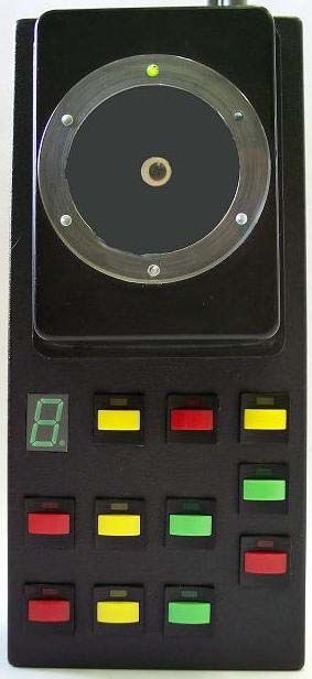
Czech Technical University in Prague, Faculty of Electrical Engineering

Department of Control Engineering                     Academic Year: 2005/2006

            Specification of Bachelor Thesis

Student:                       Acosta Serrano Javier Dario

Profile:                       Cybernetics and Measurement

Name of thesis:                Control of Model of Position Device

                            Fundamentals for elaboration:

   1.      Familiarize with programmable controller ControlLogix by Rockwell
           Automation.
   2.      Make a simple model of position device for this controller.
   3.      Prepare typical tasks of control with this model including visualization by
           means of RSView 32.
   4.      Specification of tasks and description of model place on the web of Allen-
           Bradley Laboratory.

List of special literature: supply head of thesis

Head of bachelor thesis: Ing. Jindřich Fuka

Date of specification of bachelor thesis: winter semester 2005/06

Date of committing the bachelor thesis: 30.6.2006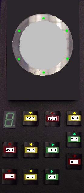
Acknowledgment

I am very thankful to my guide Ing. Jindřich Fuka, who has been very cooperative
and understanding. I owe my deepest regards to UNESCO and to the Czech
Government for giving me the fellowship that made it possible for me to study at
the Czech Technical University in Prague.

                                       i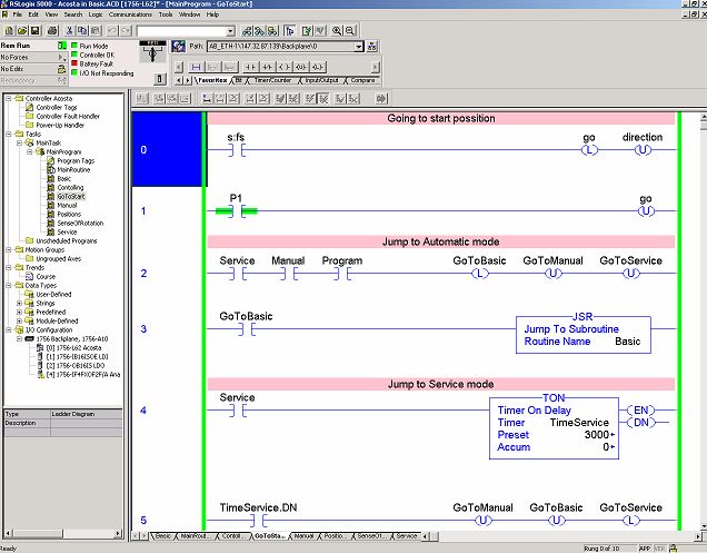
Abstract

This bachelor thesis was made mainly for education purposes, so that students
interested in control using Allen-Bradley programmable controllers can acquaint
with the latest so called PACs (Programmable Automation Controllers). Allen-
Bradley is a trade mark of Rockwell Automation. Used hardware and software are
described in the first chapter. In the second chapter the characteristics of the model
of positioning device are depicted. This device was designed and made to be
controlled with ControlLogix. The third chapter is dedicated to the explanation of
a visualization developed in RSView 32. The models of positioning device are
placed in the Allen-Bradley Laboratory at the Department of Control Engineering
of the Czech Technical University in Prague.

                                          ii
Declaration
I declare that I made my bachelor thesis by myself. I used only details
(literature, projects, SW etc.) which are mentioned on the list of used literature.
Prague …………………. …………………………………
Signature
iiiTable of Contents
Acknowledgment ...................................................................................i
Abstract ................................................................................................ ii
Declaration.......................................................................................... iii
Table of Contents ................................................................................iv
List of Figures ......................................................................................vi
List of Tables........................................................................................vi
Introduction ..........................................................................................1
1. Programmable Automation Controllers (PAC)............................2
1.1. Network Devices (Data Buses)....................................................3
1.1.1. Ethernet/IP ..............................................................................................3
1.1.2. ControlNet ..............................................................................................4
1.1.3. DeviceNet ...............................................................................................5
1.2. ControlLogix System...................................................................6
1.2.1. Hardware.................................................................................................6
1.2.1.1. Producer/Consumer Model..............................................................7
1.2.1.2. Memory ............................................................................................8
1.2.1.3. I/O Points.........................................................................................9
1.2.1.4. Used Modules ................................................................................10
1.2.2. Software ................................................................................................12
1.2.2.1. RSLinx............................................................................................12
1.2.2.2. RSView 32 ......................................................................................14
1.2.2.3. RSLogix 5000.................................................................................15
2. Model of Positioning Device ..........................................................17
2.1. Overview....................................................................................17
2.2. Specifications.............................................................................18
2.3. Construction of the Real Model.................................................19
2.3.1. Sensors and LEDs.................................................................................19
2.3.2. Motor ....................................................................................................20
2.3.3. Buttons and Switches............................................................................24
2.3.4. Voltage Source......................................................................................25
iv3. RSView 32 Visualization of Positioning Device...........................26
3.1. Settings.......................................................................................26
3.2. Visualization ..............................................................................27
Conclusion...........................................................................................29
Literature ............................................................................................30
Abbreviations......................................................................................31
Attachments ........................................................................................32
Appendix A: Lists of the Addresses and Tags in the ControlLogix 32
Appendix B: List of Used Electronic Components (in one model of
positioning device): ..........................................................................34
Appendix C: Canon 37 Connector Pins Wiring ...............................35
Appendix D: Task.............................................................................36
vList of Figures
FIGURE 1-1: USED CONTROLLOGIX 5562 MODULES ........................................................................ 10
FIGURE 1-2: RSLINX CONFIGURATION ............................................................................................. 12
FIGURE 1-3: RSLINX2 STRUCTURE ................................................................................................... 13
FIGURE 1-4: EXAMPLE OF VISUALIZATION OF THE MODEL IN RSVIEW 32 ........................................ 15
FIGURE 1- 5: PROGRAM IN RSLOGIX 5000 ....................................................................................... 16
FIGURE 2-1: OVERVIEW OF THE MODEL ........................................................................................... 17
FIGURE 2-2: SENSOR’S CIRCUIT ........................................................................................................ 20
FIGURE 2-3: CIRCUIT OF THE MOTOR’S DIRECTION .......................................................................... 21
FIGURE 2-4: CIRCUIT OF SWITCHING ON/OFF MOTOR ........................................................................ 21
FIGURE 2-5: CIRCUIT OF THE MOTOR CONTROLLED BY ANALOGUE MODE ........................................ 22
FIGURE 2-6: MANUALLY CONTROLLED CIRCUIT ............................................................................... 23
FIGURE 2-7: FINAL CIRCUIT OF MODEL OF POSITIONING DEVICE ....................................................... 24
FIGURE 2-8: PLACEMENT OF BUTTONS AND SWITCHES ..................................................................... 25
FIGURE 3-1: SET PARAMETERS IN RSVIEW 32 (TOPIC CONFIGURATION) ......................................... 26
FIGURE 3-2: SET PARAMETERS IN RSVIEW 32 (TOPIC CONFIGURATION 2) ...................................... 27
FIGURE 3-3: VISUALIZATION IN RSVIEW 32..................................................................................... 28
List of Tables
TABLE 1: LIST OF BUTTONS AND SWITCHES ...................................................................................... 24
TABLE 2: LIST OF ABBREVIATIONS ................................................................................................... 31
TABLE 3: INPUT MODULE ELEMENTS ............................................................................................... 32
TABLE 4: OUTPUT MODULE ELEMENTS ............................................................................................ 33
TABLE 5: USED ELECTRONIC COMPONENTS ..................................................................................... 34
TABLE 6: CANON CONNECTOR ......................................................................................................... 35
viIntroduction
Day by day the necessities of human beings are changing and as our thoughts
evolve, these necessities force us to think in a better and more efficient ways to
satisfy them. As the technology continues to advance in leaps, the impossible is
becoming possible, and it also becomes easer to make things that were
complicated and inaccessible before into areas where men did not dear to imagine.
Through the years men look for comfort and a good way to obtain it so as to make
easier the work for us. Automation is the part of the science that deals with
Automatic Control to make lives easier for millions of people around the world.
Temperature, Speed, Pressure, Movement and Position; are some of the factors
that can be controlled by means of the automatic controllers.
Positioning control for example, is of great importance to us and we can find it in
endless number of systems. For this type of control the use of so called PLCs
(Programming Logical Controllers) is possible, or still better and more
sophisticated PACs (Programming Automation Controllers) can be used as well.
The main purpose of this thesis is to familiarize students with programmable
automation controllers from Rockwell Automation (trade mark Allen-Bradley),
and make it easier for them to control a device with the appropriated
characteristics for beginners as well as for advanced users which are able to work
with more advanced methods of control. In this thesis it will be explained what a
PAC is, what kind of hardware it is made of, what kind of software we can use
with it and how to use this software to control a model of positioning device. For
education purposes I made three models of positioning device that are described in
this thesis too. There is also a chapter dedicated to a visualization that was made
for controlling this model from the computer.
11. Programmable Automation Controllers (PAC)
In this chapter it will be explained what a PAC is, and what are the differences
between PACs and PLCs. For that aim information and definitions from different
Internet sources are used [1].
A Programmable Automation Controller (PAC) is a compact controller that
combines the features and capabilities of a PC-based control system with that of a
typical Programmable Logic Controller (PLC). PACs are most often used in
industrial settings for process control, data acquisition, remote equipment
monitoring, machine vision, and motion control. Additionally, because they
function and communicate over popular network interface protocols like TCP/IP,
OLE for process control (OPC) and SMTP, PACs are able to transfer data from the
machines they control to other machines and components in a networked control
system or to application software and databases.
The ARC Advisory Group, an analyst group focused on the manufacturing
industry, is generally credited for originating the term "PAC". It was first coined in
2001 as a way to help users of control hardware better define their needs, and to
give the leading control hardware vendors a term to more clearly communicate the
capabilities of their products.
PAC - PLC Comparison
Generally, PACs and PLCs serve for the same purpose. Both are primarily used to
perform automation, process control, and data acquisition functions such as digital
and analog control, serial string handling, PID, motion control, and machine
vision.
Unlike PLCs, PACs offer open, modular architectures, the rationale being that
because most industrial applications are customized, the control hardware used for
them needs to allow engineers to pick and choose the other components in the
2control system architecture without having to worry whether or not they will be
compatible with the controller.
PACs and PLCs are also programmed differently. PLCs are often programmed in
ladder logic, a graphical programming language resembling the rails and rungs of
ladders that is designed to emulate old electrical relay wiring diagrams. PAC
control programs are usually developed with more generic software tools that
permit the designed program to be shared across several different machines,
processors, HMI terminals or other components in the control system architecture.
Of course ladder logic is used in PACs.
PAC processing and I/O scanning is also very different. Unlike PLCs, which
constantly scan all the I/O inputs in the control system at very high rates of speed,
PACs utilize a single tagname database and a logical address system to identify
and map I/O points as needed.
Well known control hardware vendors offering PACs include General Electric,
National Instruments, Opto 22, ICP DAS, and Rockwell Automation.
1.1. Network Devices (Data Buses)
In Programmable Automation Controllers there are used different data busses to
communicate between them and with other instruments, for example computers.
Each one serves to different purpose. As it was said before, in this thesis it will be
important Data Busses used by Allen-Bradley PACs. The most important Allen-
Bradley Data Busses are Ethernet/IP, ControlNet and DeviceNet.
1.1.1. Ethernet/IP
Ethernet/IP (Ethernet Industrial Protocol) is an open industrial networking
standard that supports both real-time I/O messaging and message exchange. The
name comes from the physical concept of ether. It defines a number of wiring and
signaling standards for the physical layer, two means of network access at the
Media Access Control (MAC)/data link layer, and a common addressing format.
3Ethernet has been standardized as IEEEs 802.3. Its star-topology, twisted-pair
wiring form became the most widespread LAN technology in use from the 1990s
to the present, largely replacing competing LAN standards such as Coaxial-cable
Ethernet, Token Ring, FDDI, and ARCNET. The primary competitor to Ethernet
in the Local Area Network market of the present is WiFi, the wireless LAN
standardized by IEEE 802.11.
Ethernet/IP represents migration of the upper level CIP (Common Industrial
Protocol) common to the ControlNet and DeviceNet networks onto the Ethernet
physical media. As a media independent protocol, CIP is capable of migrating to
further media such as FireWire or wireless networks. While Ethernet/IP is
positioned as a supervisory interface to handle information from plant floor to
higher level systems, the protocol will accommodate real time control messages
along with non time critical data transfers. Rockwell's introduction of I/O level
products such as Flex I/O and MicroLogix controllers emphasizes the real-time
capability. The high bandwidth property also lends itself to incorporation of
sensors with high data content. Cognex, for example offers a family of Ethernet/IP
compatible networked vision sensors.
While Ethernet/IP can accommodate both real-time and non time-critical messages
through its encapsulation of both the UDP and TCP protocols, critics contend that
this approach creates significant protocol overhead. The Ethernet/IP SIG (Special
Interest Group) within ODVA, or the Open DeviceNet Vendor Association, is the
keeper of Ethernet/IP-specific objects and device profiles beyond the basic CIP
specification. (This information is based on Internet sources) [2].
1.1.2. ControlNet
ControlNet is a real-time control network that provides high-speed transport of
both time-critical I/O and interlocking data and messaging data, including
upload/download of programming and configuration data on a single physical
media link. The ControlNet network’s highly efficient data transfer capability
4significantly enhances I/O performance and peer-to-peer communication in any
system or application where it is used.
ControlNet is highly deterministic and repeatable, and remains unaffected as
devices are connected or disconnected from the network. This ensures dependable,
synchronized, and coordinated real-time performance [3].
The ControlNet network is most often used in these types of configurations as a:
¾ default network for the ControlLogix platform
¾ substitute/replacement for the Universal remote I/O (RIO) network,
because ControlNet handles large numbers of I/O points
¾ backbone to multiple distributed DeviceNet networks
¾ peer communication network
¾ high-speed I/O network
1.1.3. DeviceNet
The DeviceNet network is an open device level network that provides connections
between simple industrial devices (such as sensors and actuators) and higher-level
devices (such as programmable controllers and computers). Uses the proven
Common Industrial Protocol (CIP) to provide the control, configure, and data
collection capabilities for industrial devices. DeviceNet is a flexible network that
works with devices from multiple producers [3].
Some of the DeviceNet features are:
¾ Cost-effective networking solution to simple devices
¾ Easily access data in intelligent sensors/actuators from multiple third party
vendors
¾ Provides master/slave, Change-of-State, and peer-to-peer capabilities
¾ Producer/Consumer services let you configure devices, control, and collect
information over a single network
5¾ Improves system integration for both safety and standard applications
¾ Reduces downtime with early detection of system performance problems
¾ Reduces maintenance costs with diagnostics and automatic device
replacement
1.2. ControlLogix System
Recently, coordinated drive control, motion control, process control and sequential
control have been each accomplished using disparate hardware and software
products. The ControlLogix architecture, on the other hand, paves the road toward
integration of these control disciplines in a seamless manner that gives the control
designer a common software tool set and a common hardware platform [4].
As part of the Rockwell Automation Integrated Architecture, Logix platforms
provide single control architecture for discrete, drives, motion and process control
systems. Whether is needed a high-performance control system or a small, value-
based control system, these platforms provide the right control system for all
applications.
The ControlLogix controllers support intensive process applications and provide
fast processing of sequential, motion, process, and drives applications. Multiple
controllers, communication modules and I/O can be mixed without restriction. No
processor is needed to perform bridging and routing of I/O and, as the system
grows, the network permits distributing control to additional chassis [3].
1.2.1. Hardware
ControlLogix System is made up of a main chassis and separated modules. In this
chapter will be named and described used modules, for that reason definitions and
information from different internet sources will be used [4].
61.2.1.1. Producer/Consumer Model
One of the key features of the ControlLogix system is that communications
functions are designed into every layer of the system starting with the backplane
and on through to the I/O modules, the processors and, of course, the
communications modules themselves. The ControlLogix backplane is a first
cousin to the ControlNet network and utilizes the same Producer/Consumer Model
that ControlNet does. Producer/Consumer is the name we give to a communication
model whereby network nodes or modules on the chassis, each produce data.
Other nodes or modules can then consume that data on an as-needed basis without
having to make discreet requests. This is vastly different from other models where,
for example, a master must manage the communications task by asking each node
or module if it has a message to send and arranging the transaction.
For processors, the use of the producer/consumer paradigm allows for the
installation of multiple processors in the same chassis. In this way, the backplane
itself acts as a high-speed network, which provides communications capabilities
between all the modules on the backplane - as well as those that are extended out
to other chassis' on ControlNet. For this reason, the capabilities, of the
ControlLogix system are also extended well beyond those of the traditional
programmable controller. Gateway functionality is a product of this
communications architecture. Before the Logix5562 controller was released, the
Ethernet, ControlNet and Data Highway Plus (DH+) modules, (along with chassis
and power supplies,) were released to form the ControlLogix Gateway product.
The ControlLogix Gateway allows bridging and routing of messages between the
various networks without the need for a PLC or other controller to be present in
the system. This communications capability is possible because of the backplane's
new model of acting as a network itself. Messages can now be routed from one
'link' to another (and in this model the backplane is another 'link' in the path)
because of this very flexible and powerful communications model.
7Multiprocessor support is also a spin off from the Producer/Consumer Model.
Multiprocessing is supported in the chassis for any number of slot locations and
for any combination of slots. Since the backplane acts like a high-speed network,
each processor is like a node on that network; therefore, any number of processors
can communicate to any other, regardless of the slot location of those processors.
In this manner, a PLC and DCS processor for instance can co-exist in the same
backplane or network, share the field I/0 and exchange data between each other.
A software configuration tool, RSNetworx is used to assign processor ownership
output to devices. A given processor operates on the premise that it seamlessly
owns all input devices and user designated output devices on the network.
Finally, with the Producer-Consumer backplane, many of the boundaries and
limitations inherent to older technologies disappear. Since each processor now acts
like a node on a high-speed network, there is no single master or bus arbitrator for
all communications and control on the backplane. For this reason, any failure of a
single processor does not necessarily commit the control system to shutdown. If a
given processor is not controlling a mission critical function, the rest of the control
may indeed stay running while the processor in question is removed and replaced
under Power.
1.2.1.2. Memory
Controller memory is another area where the ControlLogix system offers
considerable flexibility, utilizing technologies that outpace other controllers in its
class. In adding memory to the Logix5562 controller, there are no fixed areas of
memory allocated for specific types of data or for I/O. There is no artificial limit
on the number of timers, counters or instructions. Memory is contiguous within
any given controller and is utilized 'from top to bottom' as the user develops the
application. In the ControlLogix chassis, memory is added specifically to each
Logix5562 controller and tags are passed between processors like I/O within the
system. This allocation of memory on a processor-by-processor basis is one of the
reasons why processors can 'live' in any slot location in a chassis and with any
number of processors in a dual chassis.
81.2.1.3. I/O Points
As stated earlier, the ControlLogix system does not impose artificial boundaries on
the number of I/O points that a control system can have. When I/O points are
configured or when application code is created, memory is used contiguously.
Therefore one of the limiting elements for the number of I/O points in the system
is, of course, memory. If more memory is needed, the user can add more memory
via a memory expansion card or add another processor to the chassis to increase
the total number of I/O points in the system. A second factor that may bind the
total number of I/O points for a given processor involves the concept of
connections. The ControlLogix system uses a connection to establish a
communication link between two devices. These devices may be controllers,
communication modules, I/O modules, produced and consumed tags or messages.
Connections are quite different from individual I/O points. Each Logix5562
controller, for example, is capable of making 250 connections. In one
configuration, a single connection may be made to an entire chassis. Considering
the fact that 17 slot chassis are available, and assuming 32 point modules in our
calculations, a single processor may actually support up to 128 000 digital I/O
points; 4000 analog I/O points can be supported using similar calculations for
analog I/O. Although these numbers we large in themselves they double as a
second processor is added to a rack - and they triple with the third, etc. Although
these numbers may seem extreme when viewed in this manner, the point remains
that the ControlLogix architecture does not impose an artificial limit on the total
number of I/O points that can be supported for any given application.
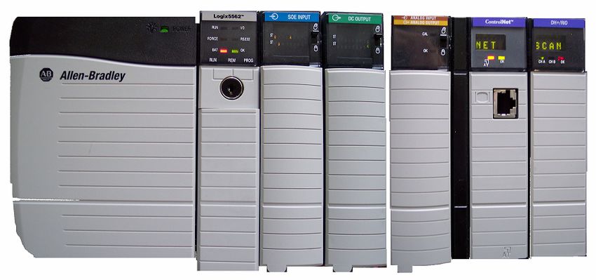
91.2.1.4. Used Modules
Let’s see typical configuration of input and output modules in our control
application.
Figure 1-1: Used ControlLogix 5562 Modules
Module 1756-IB16ISOE/A (Digital Input)
This is a module with 16 digital inputs and 16 GNDs connected together and to -
12 V of DC source in our case. Maximum input voltage is 31.2 V. Logical 0 is
defined from 0 to 5 V and logical 1 is defined from 10 to 31.2 V.
Module 1756-OB16IS/A (Digital Output)
The 1756-OB16IS is a 16 point, 10-30 V, sink/source DC output module. It is
identical to the 1756-OB16I module except when used with the Motion Arm
Output Cam (MAOC) instruction. When used with an MAOC instruction, it
provides very accurate and consistent latch and unlatch output events for the first 8
outputs.
Module 1756-IF4FXOF2F/A (Analogue I/O)
This is a fast analogue module with 4 high-speed, sub-millisecond, differential
inputs and 2 high-speed voltage or current outputs, it supports ±10 V of input
10voltage, on-board data alarming, scaling to engineering units and real-time channel
sampling.
Module 1756-CNB/D
This ControlNet network module is an open, state-of-the-art control network that
meets the demands of real-time, high-throughput applications. The ControlNet
network uses the proven Common Industrial Protocol (CIP) to combine the
functionality of an I/O network and a peer-to-peer network providing high-speed
performance for both functions.
It gives repeatable transfers of all mission critical control data in addition to
supporting transfers of non-time-critical data. I/O updates and controller-to-
controller interlocking always take precedence over program uploads and
downloads and messaging. It supports from 40 to 48 connections in any
combination of scheduled and unscheduled. This Module is not used, but I would
be used as well.
Module 1756-ENBT/A
The 1756-ENBT/A ControlLogix EtherNet/IP Module is an enhanced version of
the 1756-ENET/A ControlLogix EtherNet/IP Module. This new version of the
module communicates at faster rate than its predecessor (10/100 Mbps full duplex
vs. 10 Mbps half-duplex) and includes more on-board memory. These
enhancements better enable you to transfer large amounts of informational
messaging and time-critical I/O and control data simultaneously over a single
EtherNet/IP network.
The module displays five-character diagnostic indicators that help to troubleshoot
problems much more easily than with simple LED lights – saving time and
minimizing any guesswork.
111.2.2. Software
ControlLogix controllers are compatible and can be used with different software,
depending on user’s needs. Internet sources [3] and [5] are again used in this
chapter.
1.2.2.1. RSLinx
RSLinx is windows based communication software package developed by
Rockwell Software to interface to all of the Rockwell and A-B industrial control
and automation hardware. RSLinx comes in a variety of different flavors including
Figure 1-2: RSLinx Configuration
¾ RSLinx-Lite – PLC Programming software communication interface.
¾ RSLinx-OEM – Provides DDE capability for Rockwell DDE capable
software.
12¾ RSLinx Professional – Provides DDE capability to and DDE capable
software.
¾ RSLinx-Gateway – Communication network bridging, routing, and OPC
server.
¾ RSLinx SDK – Software Development Kit includes the OEM version.
In actuality, all of the RSLinx software packages are the same. What differentiates
the software packages from one other is the copy protection software key for
RSLinx. If you run RSLinx without a software key the software operates in the
lite mode. If you have a key the software operates in the mode that the software
key authorizes it to run in.
RSLinx is the intermediary between the communication hardware and the software
package that needs data from the communication hardware.
Figure 1-3: RSLinx2 structure
For RSLinx to function it must be configured to use the communication hardware
interface of your choice. Choosing the correct communication hardware interface
requires a thorough understanding of the device that is to be communicated with.
In the case of communicating with a PLC it is important to understand the
communication capability of the specific PLC that is being used. Different types,
models and revisions of PLCs have different communication capabilities.
For our application we use Ethernet communication. We had to configure Ethernet
devices driver {AB_ETH-1, Ethernet} and our communication module has an IP
address 147.32.87.139 (Figure 1-2). We can see all modules on local ControlBus
network.
131.2.2.2. RSView 32
RSView 32 is software use for monitoring and controlling automation machines
and processes. It provides unprecedented connectivity to other Rockwell Software
products, Microsoft products, and third-party applications. RSView 32 can be a
client/server application that extends the view of data by allowing remote
operators to open, run, and interact with RSView 32 graphic displays from
virtually any computer on a network. This extends the reach of process control
system from the plant floor to the office and beyond. RSView 32 takes advantage
of Microsoft Distributed Component Object Model (DCOM) and ActiveX
technologies, allowing remote components to appear local and by providing
convenient Internet access.
RSView 32 allows:
¾ View and interact with real-time, animated graphics
¾ Manage and control alarms, trends, and set-points
¾ Manage and acknowledge global alarms
¾ Centrally manage configuration files, graphic display files, databases, and
RSView 32 security
¾ Centrally administer the RSView 32 security system
¾ Automatically deploy client software through your network from the
Microsoft Internet Explorer browser on a client
¾ Automatically establish client sessions with an alternate server if the
primary server fails
¾ Use RSView 32 Active Display with Microsoft Windows Terminal
Services to reduce total cost of ownership. Combine RSView 32 Active
Display and Terminal Services to use thin clients, such as the Microsoft
Windows CE-based RAC6182 and MobilView that remotely access
RSView 32 information.
14Figure 1-4: Example of visualization of the model in RSView 32
1.2.2.3. RSLogix 5000
RSLogix 5000 is windows based communication software developed by Rockwell
Software and designed to work with the Rockwell Automation Logix platforms:
ControlLogix, CompactLogix, FlexLogix, SoftLogix5800 and DriveLogix.
15Figure 1- 5: Program in RSLogix 5000
The RSLogix 5000 environment offers an interface simple to use, symbolic
programming with structures and arrays, and a comprehensive instruction set that
serves many types of applications. It supports relay ladder, structured text,
function block diagram, and sequential function chart editors for you to develop
application programs.
RSLogix 5000 fully uses function drag and drop; it increases speed and
effectiveness of writing programs. Of course there is a possibility of showing
variables in a graph. Translating module for transformation of programs of
controllers SLC500 and PLC5 is content of software RSLogix 5000. Using this
module considerably reduce costs and spend time.
162. Model of Positioning Device
An important part of this work consists of the design and construction of a model
of a positioning device. The device will be connected to and controlled by the
ControlLogix system. I designed and made three models. For the design of the
electronic circuit, I improved a previous design made by Mr. Karasek in his thesis
[6].
Figure 2-1: Overview of the Model
2.1. Overview
The outside of the model of the positioning device consists of a black box that has
two levels. The first level contains 6 buttons and 5 switches with its respective
LEDs (each one of a different color (green, yellow and red), and also there is a
seven segment display. In the second level, there are 6 LEDs separated by the
same distance from the center (25 mm). These LEDs are arranged in a circle with
the adjacent LEDs making a 60 degree sector angle. The LED display is covered
17by circular glass that enables us to see the inside of the box. There is metallic
rotating disk which is placed between six sensors. The disc is driven by a small
DC motor with gearing.
2.2. Specifications
The model consists of six sensors arranged in a circular shape with the sector
angles 60, 120, 180, 240, 300 and 360 degrees, respectively. Each sensor is placed
25 mm from the center. These position sensors are optical sensors: TCST 1013.
The sensor consists of the light-emitting source and the detector that are placed
face-to-face on the same optical axis approximately in 3 mm distance. It allows to
place between them an obstacle to prevent the light of the emitter diode to be
detected by the phototransistor.
In my work, I used metallic disc of width 1 mm and diameter 50 mm that rotates
between sensors. The disc, that has a hole of 5 x 5 mm in the outer edge, is placed
in such form, that it prevents the sensors detect the light of their respective emitter.
When the disc rotates and the hole passes through a sensor, the phototransistor
detects the light of the LED and sends a signal to the controller which enables to
find the position of the hole. At the same this sensor indicates the position of the
hole by switching on the LED placed just upon the sensor. There are altogether 6
LEDs, each one just upon its respective sensor.
In order to rotate the metallic disc between the sensors, I decided to use a small
servomotor Hitec HS-311 with gearing in a plastic box which can rotate in both
directions: clockwise and counter-clockwise. The switching-on, switching-off,
direction of rotation and the number of revolutions of the motor, are controlled by
the controller (ControlLogix).
The internal circuit of the model works with +12 Volts DC, GND and -12 Volts
DC. It consists of an amplifier (to load the motor), a circuit for switching-on and
18switching-off of the motor, a circuit for the operation of the sensors and LEDs and
a circuit for the operation of buttons, switches and a seven segments display. The
seven segment display is controlled by the ControlLogix and can be programmed
to indicate the position number. It is also possible to control the motor manually
by pushing the “Manual-B1” button, but in this case current flows and the motor
starts moving only in one direction, though the sensors and LEDs work normally.
2.3. Construction of the Real Model
I used small and big plastic boxes for body of the model. The small one (29x65x90
mm) is placed over the big one (49x90x200 mm). This arrangement permits to
place the motor with its gearing in to lower part. The upper part is ideal for placing
the sensors and the rotational disk. Inside the big box there are placed the
electronic circuits of the motor and the voltage divider which controls the direction
of rotation of the motor. The circuits of the sensors and LEDs are placed inside the
small box.
2.3.1. Sensors and LEDs
Sensors have a compact construction where the emitting-light source and the
detector are located face-to-face on the same optical axis. The operating
wavelength is 950 nm. The detector consists of a phototransistor and the emitter is
an LED. In the model, I used 6 sensors, all placed in a circle with an angle
between them of 60 degrees. The connection of the circuit for these sensors and
their corresponding LEDs (LEDs indicates when phototransistor detects light from
emitter) were made according Mr. Karasek’s thesis [6].
19Figure 2-2: Sensor’s circuit
When the hole of the rotating disk passes through a sensor, light opens inner
transistor of the sensor. Due to transistor T1 also opens. Current flows through the
LED, which illuminates, and also output is on.
2.3.2. Motor
The used motor is a small servo motor Hitec HS-311 Servo Motor. In the motor I
did some changes: first of all I removed the electronic circuit included to control
the motor (I didn’t need it any more because I made my own). Next step was to
eliminate a part of the potentiometer that does not allow the motor to rotate more
than 270 degrees.
Direction of the motor
To control the direction of the motor I made a voltage divider with input of ±12 V
and output of ±4 V approximately. For that reason there were placed also two
variable resistors that can be set to a different value to increase or decrease voltage
if needed (Figure 2-3).
20Figure 2-3: Circuit of the Motor’s direction
Switching on/off circuit
For switching motor I use two transistors that work like switches when current
passes trough them. There must be also two diodes connected to the transistors to
improve switching process.
Figure 2-4: Circuit of switching on/off motor
Control of the Switching on/off of the motor is controlled by the ControlLogix.
21There are three different possibilities to control the motor:
1. Digital Manner
When controlling in digital form, we use the ControlLogix with digital
modules 1756-IB16ISOE/A and 1756-OB16IS/A. In this case, the
ControlLogix controls motor’s switching on/off and direction. It allows
moving in both directions at the constant speed (See figure 2-3 and 2-4).
2. Analogue Manner
When controlling by analogue manner we use also ControlLogix analogue
module 1756-IF4FXOF2F/A. It allows controlling not only the direction
but also the speed of the motor by increasing or decreasing voltage
(max/min voltage ±10 V) (Figure 2-5). For the control with analogue
module it was necessary to design a circuit to stabilize voltage to ± 10 V.
This voltage supplies potentiometer which is connected to rotational disk.
It allows analogue measuring of the position of the hole.
Figure 2-5: Circuit of the motor controlled by analogue mode
223. Pushing “Manual-B1” Button:
The positioning device can be controlled without ControlLogix by pushing
“Manual-B1” button. It is needed just to connect the model to a source of
±12 V. In this case the motor can rotate only in one direction at the same
speed.
Figure 2-6: Manually controlled circuit
Figure 2-7 presents the complete design of the circuit:
23Figure 2-7: Final circuit of model of positioning device
2.3.3. Buttons and Switches
The model has 6 buttons and 5 switches; Button 1 can control the position, without
controller, Button 2 and Button 3 is Start and Stop Button respectively. Buttons 4,
5, and 6 are respectively Program, Manual and Service Buttons. These buttons are
for switching between different modes. The Switch 1 switches between Analogue
and Digital mode, switch 2, 3, 4 and 5 can be use for programming purposes.
Label Name Function
B1 Button 1 B1-Manual
B2 Button 2 Start
B3 Button 3 Stop
B4 Button 4 Program
B5 Button 5 Manual
B6 Button 6 Service
SW 1 Switch 1 D/A Switch
SW 2 Switch 2 Free
SW 3 Switch 3 Programmable
SW 4 Switch 4 Programmable
SW 5 Switch 5 Programmable
Table 1: List of buttons and switches
24Figure 2-8: Placement of buttons and switches
2.3.4. Voltage Source
The model is powered by two voltage sources of 12 V / 0.5 A in series. The +12 V
output of one power supply is connected to common terminal of another power
supply. The connection is used like analog GND or 0 V. The common of the first
power supply is used like -12 V for the analogue part of circuitry and also as
digital GND. Then +12 V of the second power supply is 24 V for the digital part.
253. RSView 32 Visualization of Positioning Device
Important part of this thesis is to prepare typical tasks of control using the model
of positioning device including visualization by means of RSView 32. I prepared
tasks that consist of two parts: a program in RSLogix 5000 software and
visualization in RSView 32 software. The task that is attached in Appendix C, can
be found on webpage of the Allen-Bradley’s Laboratory.
3.1. Settings
Before starting with the RSView 32 it is necessary to set parameters in RSLinx so
that it can point to our work. We can do that by choosing the option “DDE/OPC”
and then clicking on “Topic Configuration…” option.
Figure 3-1: Set parameters in RSView 32 (Topic Configuration)
In the appearing window we can make a new topic list and set the way that points
to our project in ControlLogix processor or we can use an exiting Topic with
parameters already defined. Figure 3-2 depicts topic “Krab” for my project.
26Figure 3-2: Set parameters in RSView 32 (Topic Configuration 2)
3.2. Visualization
When designing the view of our visualization it is very important to take in
account that it has to be user friendly entourage so that it will be easy to use. Since
the used methods for doing visualization is up to students, it is recommendable to
separate processes and modes of control in different windows. An example of how
can be it done is to create a main window containing a menu in which can be
placed links to individual control modes Automatic Mode, Manual Mode, and
Service Mode.
27Figure 3-3: Visualization in RSView 32
28Conclusion
The first objective of this Bachelor Thesis was to familiarize with programmable
automation controller ControlLogix from Rockwell Automation. I have explained
structure of PACs and PLCs, data busses, used software and hardware, and
components like I/O modules.
Further it was required to design and make a model of positioning device which is
connected and controlled by the ControlLogix controller. Three models were
successfully designed, made and tested. The circuit of the model and a picture of it
can be seen in Figure 2-7 and Figure 2-1 respectively.
Typical tasks of control for students using the model of positioning device and the
ControlLogix controller were also prepared (See appendix D). For solving these
tasks is necessary to use software installed in the Allen-Bradley Laboratory:
RSLinx, RSLogix 5000 and of course RSView 32 for visualization. The task was
satisfactory tested on my model. The model can be used for other tasks from
simple one (start and stop motor) to much complex (control of traffic lights).
Specification of task and description of model were prepared but due to
reconstruction of the web of the Allen-Bradley Laboratory, they will be updated
later there. It will be possible to find them at .
29Literature
[1] Wikipedia, Free Encyclopedia
[2] Ethernet, Industrial Networking, the online Industrial Ethernet Book
[3] ControlLogix Digital I/O Modules User Manuals, March 2001
[4] Allen-Bradley ControlLogix, Woodrow,
[5] PLC archive,
[6] Milan Karásek, Thesis (Diplomová Práce) Prague 2002, Czech Technical
University in Prague (C.T.U.), Department of Control Engineering.
30Abbreviations
LED Light emitting diode
PAC Programmable Automation Controller
PLC Programmable Logic Controller
i.e. Id est (That is)
e.g. Exempli gratia (for example)
IP Internet Protocol
OLE Object Linking and Embedding
I/O Input/Output
SMTP Simple Mail Transfer Protocol
PID Proportional Integral Derivative
CIP Common Industrial Protocol
MAC Media Access Control
UDP User Datagram Protocol
TCP Transmission Control Protocol
SIG Special Interest Group
Table 2: List of Abbreviations
31Attachments
Appendix A: Lists of the Addresses and Tags in the ControlLogix
Input Module
Input Elements Address in the ControlLogic Name of Tag
Stop Button 'Red' Local:1:I.Data.0 Stop
Start Button 'Green' Local:1:I.Data.1 Start
Program Button 'Green' Local:1:I.Data.2 Program
Manual Button 'Yellow' Local:1:I.Data.3 Manual
Service Button 'Red' Local:1:I.Data.4 Service
Bit Switch 1 'Green' Local:1:I.Data.5 SWGreen
Bit Switch 2 'Yellow' Local:1:I.Data.6 SWYellow
Bit Switch 3 'Red' Local:1:I.Data.7 SWRed
Free Switch 'Red' Local:1:I.Data.8
Position 1 from sensor Local:1:I.Data.9 P1
Position 2 from sensor Local:1:I.Data.10 P2
Position 3 from sensor Local:1:I.Data.11 P3
Position 4 from sensor Local:1:I.Data.12 P4
Position 5 from sensor Local:1:I.Data.13 P5
Position 6 from sensor Local:1:I.Data.14 P6
Not used Local:1:I.Data.15
Table 3: Input Module Elements
]
32Output Module
Output Elements Address in the ControlLogic Name of Tag
Switch On-Off Servo-Motor Local:2:O.Data.0 Motor
Control of motor's direction Local:2:O.Data.1 Direction
Program LED 'Green' Local:2:O.Data.2 Lprogram
Manual LED 'Yellow' Local:2:O.Data.3 Lmanual
Service LED 'Red' Local:2:O.Data.4 Lservice
7 segment display a Local:2:O.Data.5 Sega
7 segment display b Local:2:O.Data.6 Segb
7 segment display c Local:2:O.Data.7 Segc
7 segment display d Local:2:O.Data.8 Segd
7 segment display e Local:2:O.Data.9 Sege
7 segment display f Local:2:O.Data.10 Segf
7 segment display g Local:2:O.Data.11 Segg
7 segment display point Local:2:O.Data.12 Segp
Green LED Local:2:O.Data.13 Lstart
Red LED Local:2:O.Data.14 Lstop
Yellow LED Local:2:O.Data.15 Lyellow
Table 4: Output Module Elements
33Appendix B: List of Used Electronic Components (in one model of
positioning device):
Resistors: Pieces
5k6 1
2k4 34
10k 1
22k 1
2k8 1
1k2 1
Diodes:
1N4007 2
Transistors:
BC337 9
Sensors:
TCST 1003 6
LEDs:
L-HLMP-1503 6
Buttons:
P-0SRB 6
Switches:
P-1SEB 5
Servo Motor:
Hitec HS-311 1
Variable
resistors:
- 3
Op-Amp:
L272M 1
Voltage
sources:
12 V 2
Table 5: Used Electronic Components
34Appendix C: Canon 37 Connector Pins Wiring
Pin 1 + 12 V. Pin 20 Out 5
Pin 2 GND Pin 21 Out 6
Pin 3 - 12V. Pin 22 LED 3
Pin 4 Seven Segment 7 Pin 23 LED 1
Pin 5 Seven Segment 4 Pin 24 LED 2
Pin 6 Seven Segment 1 Pin 25 LED 5
Pin 7 Seven Segment 3 Pin 26 Button 2
Pin 8 Seven Segment 8 Pin 27 Button 3
Pin 9 Seven Segment 5 Pin 28 Button 4
Pin 10 Seven Segment 2 Pin 29 Button 5
Pin 11 Seven Segment 6 Pin 30 Button 6
Pin 12 Motor on Pin 31 Switch 5
Pin 13 Analogue control Pin 32 Switch 4
Pin 14 Direction control Pin 33 Switch 3
Pin 15 LED 4 Pin 34 Switch 2
Pin 16 Out 1 Pin 35 Analogue position
Pin 17 Out 2 Pin 36 Free
Pin 18 Out 3 Pin 37 LED 6
Pin 19 Out 4
Table 6: Canon Connector
35Appendix D: Task
Write a program for the automatic controller ControlLogix that is connected to the
model of positioning device. The program will provide motion of model in three
different control modes. Make visualization of the system by means of software
RSView 32.
The device operates in three working modes. The automatic mode is designed for
automatic repeated production. Manual mode is determined for single-part
production. Service mode is used for repairing device. Choice of working mode is
determined by Manual, Automatic and Service buttons and is signalized by LED
diode placed over each button. The program can be operated either directly from
model or from RSView 32. Description of modes:
¾ Automatic: In this mode the system remembers up to 10 required positions
that must be fulfilled in order of setting. 3 switches and 3 buttons should be
used to enter 6 different positions. The system waits 2 seconds in the
required position and then continues to the next pre-selected position in the
shortest way. The number of the position that is going to is displayed on
the seven-segment display. By pushing Start button the sequence starts.
¾ Manual: The number of required position is submitted by means of
switches, the number is given in binary number system. After pushing one
button, the system goes to the required position in the shortest way. Next
run happens after new setting of the position.
¾ Service: This mode is only available when controlling from model. The
motor runs by pushing Start button and stops by pushing Stop button. The
sense of the direction is set by the Yellow switch.
The current operation can be canceled and the device must be stopped when Stop
button is pushed in any mode longer than 5 seconds.
36The controller is equipped with digital diagnostic modules IB16D and OB16D.
Study the characteristics of diagnostic of these modules. The model has the
possibility to interrupt the circuit of one input and one output. In the controller
program include the testing of disconnecting of input and output circuits and the
reaction on this type of fault.
If using analog control of speed, control the speed of motor by means of voltage
change.
As a basis for your program you can use a copy of prepared exemplary programs
with prepared database of basic variables.
37You can also read