Fusion EXO Beam 10 - Software version V1.0.00 - German Light Products
←
→
Page content transcription
If your browser does not render page correctly, please read the page content below
Fusion EXO Beam 10
User Manual

              Software version V1.0.00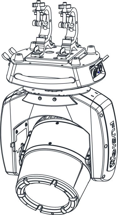
GLP® Fusion EXO Beam 10 User Manual – Revision A
This document covers fixture software version V1.0.00

© 2019 German Light Products GmbH. All rights reserved.
The marks ‘GLP’ and ‘German Light Products’ are trademarks registered as the property of German
Light Products GmbH in Germany, in the United States of America and in other countries.
The information contained in this document is subject to change without notice. German Light
Products GmbH and all affiliated companies disclaim liability for any injury, damage, direct or
indirect loss, consequential or economic loss or any other loss occasioned by the use of, inability to
use or reliance on the information contained in this document.
Manufacturer’s head office:
German Light Products GmbH (GLP), Industriestrasse 2, 76307 Karlsbad, Germany
Tel (Germany): +49 7248 92719 - 0
Service & Support EMEA:
GLP, Industriestrasse 2, 76307 Karlsbad, Germany
Tel. (Germany): +49 7248 9271955
Email: support@glp.de
www.glp.de
Service & Support USA:
GLP USA, 1145 Arroyo St., Ste. A, 91340 San Fernando, California
Tel (USA): +1 818 767 8899
Support (US): info@germanlightproducts.com
www.germanlightproducts.com
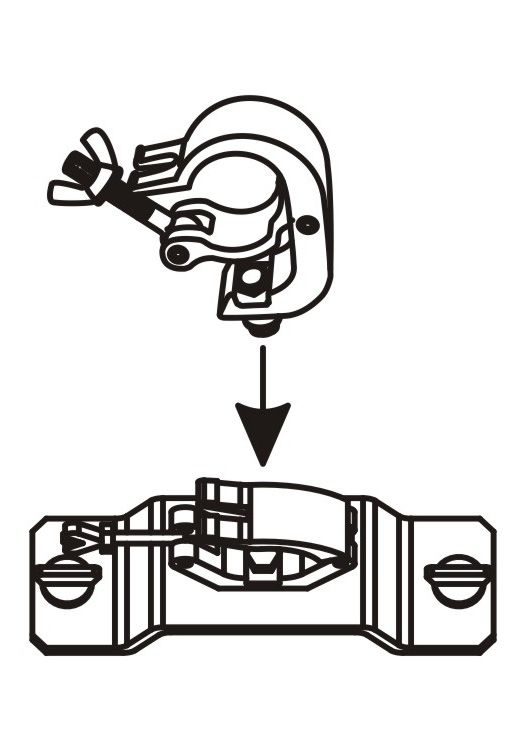
Table of Contents

1.   Safety .............................................................................................................5
         Key to symbols.........................................................................................5
         General safety information ...................................................................5
         Electrical safety .......................................................................................6
         Fire safety and protection from burns .................................................7
         Eye safety ................................................................................................. 8
         Strobe safety............................................................................................8
         Installation safety and protection from personal injury .................... 9
2.   Avoiding damage to the fixture ..............................................................10
         General precautions ............................................................................10
         Avoiding damage from light sources and heat ..............................10
         IP rating...................................................................................................11
         Avoiding damage from water and humidity...................................11
         Avoiding damage from dust and airborne particles......................12
         Transportation and storage.................................................................12
         GLP Service and Support.....................................................................12
3.   EXO Beam 10 overview .............................................................................13
4.   Installation ...................................................................................................15
         Permitted mounting options ...............................................................15
         Securing fixtures with a safety cable .................................................15
         Installing on a rigging truss or similar structure..................................16
         Standing on a horizontal surface .......................................................17
5.   AC mains power.........................................................................................18
         Included items.......................................................................................18
         Connecting to power ..........................................................................18
         Installing power connectors................................................................19
         Connecting multiple fixtures to power in a chain ...........................19
6.   Connecting to DMX data.........................................................................20
7.   Starting and stopping operation .............................................................21
8.   Features .......................................................................................................22
         Position....................................................................................................22
         Color wheel ...........................................................................................22
         Gobo wheel...........................................................................................23
         Dimming .................................................................................................23
         Strobe / shutter......................................................................................24
         Prism ........................................................................................................24
         Behavior when the fixture is not receiving a DMX signal................24
9.   Control menus and onboard display......................................................25
         Display options ......................................................................................26
         Display Locking .....................................................................................26
         Manual Control .....................................................................................26
         LED PWM frequency .............................................................................26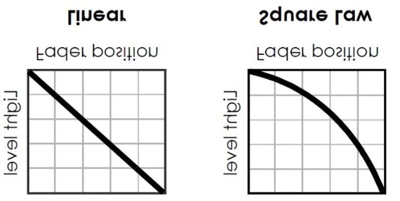
Fan control.............................................................................................26
           Fixture information ................................................................................26
           Pan disable / Tilt disable ......................................................................27
           Preset settings and factory defaults ..................................................27
10. Control menu layout..................................................................................28
           Service Advanced menu ....................................................................30
11. DMX control mode overview ...................................................................31
12. DMX control channel layout tables ........................................................32
           DMX Mode 1: Standard .......................................................................32
13. Service .........................................................................................................35
           Cleaning.................................................................................................35
           GLP Service and Support.....................................................................35
14. Technical specifications............................................................................36
           Optics......................................................................................................36
           Control....................................................................................................36
           Installation ..............................................................................................36
           Electrical.................................................................................................36
           Connections ..........................................................................................36
           Construction ..........................................................................................36
           Thermal ...................................................................................................36
           Included items.......................................................................................37
           Dimensions and weight........................................................................37
15. Dimensions ..................................................................................................38
German Light Products®                   Safety

1. Safety

Key to symbols
The following symbols are used in the Fusion EXO Beam 10 lighting fixture’s user
documentation:

             Warning! Safety hazard.                      Warning! Hazardous voltage.
             Risk of severe injury or                     Risk of lethal or severe
             death.                                       electric shock.

             Warning! See user
             manual for important                         Warning! Fire hazard.
             safety information.

             Warning! Risk of eye
             injury.

General safety information
Read this manual carefully before installing, using or servicing the Fusion EXO Beam 10
lighting fixture.
If you have any doubts or questions about how to use the fixture safely, contact your
GLP® supplier for assistance. Your GLP supplier will be happy to help.
The user documentation for GLP Fusion EXO Beam 10 lighting fixtures consists of:
● This document, the EXO Beam 10 User Manual, supplied with the fixture and
  available for download from www.glp.de. The User Manual contains important
  safety information and installation instructions that the installer and user must read.
● The EXO Beam 10 DMX Channel Index, available for download from www.glp.de.
  The Channel Index is a separate guide to the DMX control channel layout and DMX
  commands available.
All documents are available for download from www.glp.de.
The Fusion EXO Beam 10 is intended for use by experienced professionals with the
knowledge and skills to set up, operate, and maintain high-powered, remotely
controlled lighting equipment safely and efficiently. These operations require expertise
that may not be provided in this Manual or in the User Manual.
● Respect all warnings and directions given in the fixture’s user documentation and
  on the fixture. Read the user documentation and familiarize yourself with the safety
  precautions it contains before installing or using the fixture. GLP and affiliated

EXO Beam 10 User Manual Rev. A                                                              5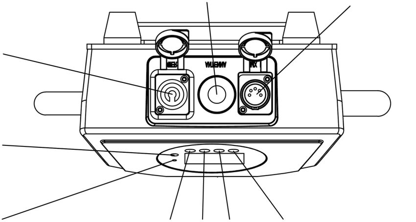
www.glp.de                                Safety

    companies will take no responsibility for damage or injury resulting from disregard for
    the information in the user documentation.
● Check the GLP website at www.glp.de and make sure that you have the latest
  version of this manual. Check the fixture software version indicated on page 2 of this
  manual and then use the fixture’s control panel to check the version installed in the
  fixture. If the versions are not the same, this manual may still cover the fixture,
  because software updates do not always affect the way you use the fixture.
  However, it is possible that this manual does not match the fixture perfectly.
  Software release notes can help clarify this question. You can consult software
  release notes and download the correct version of this manual on the GLP website if
  necessary.
● Make all user documentation available to all installers and operators. Save this
  document for future reference.
● If you have any questions about the safe operation of the fixture, please contact an
  authorized GLP distributor (see list of distributors at www.glp.de).
● Use the fixture only as directed in this manual. Observe all markings in this manual
  and on the fixture.
● Refer all repairs and any service operation not described in this manual to a
  technician authorized by GLP.
● The light source in this fixture must not be changed by the end user.
● Read and follow the user documentation for all additional equipment.

Electrical safety
● Do not allow the fixture to become immersed. Do not expose the fixture to high-
  pressure water projections.
● Keep any unused connectors on the fixture sealed with their protective caps at all
  times, both when the fixture is in use and when not in use.
● Use only a source of AC mains power that complies with local building and
  electrical codes and has both overload and ground fault (earth fault) protection.
● Ensure that the fixture is electrically connected to ground (earth).
● Disconnect the fixture from AC mains power before carrying out any installation or
  maintenance work and when the fixture is not in use.
● Disconnect the fixture from power immediately if any seal, cover, cable, connector
  or other component is damaged, defective, deformed or showing signs of
  overheating. Do not reapply power until the fixture has been repaired and made
  safe by a technician authorized by GLP.
● Check that all power distribution equipment, cables and connectors are in perfect
  condition, rated for the electrical requirements of all connected devices, suitable
  for their application and suitable for the installation environment.

6                                                       EXO Beam 10 User Manual Rev. A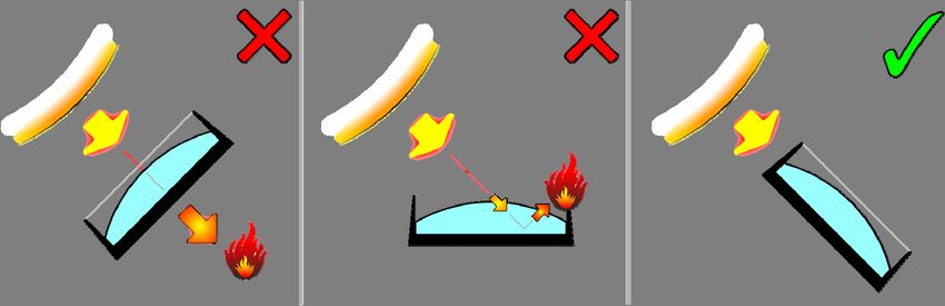
German Light Products®                    Safety

● Use only Neutrik PowerCON TRUE1 cable connectors for AC mains power input at
  the fixture’s Mains IN connector and for relaying AC mains power from one fixture’s
  Mains OUT (Thru) connector to another fixture’s Mains IN connector.
● Use minimum 14 AWG or 1.5 mm2 power input and relay cables that are minimum
  16 A-rated and temperature-rated to suit the application. In the USA and Canada
  the cables must be UL-listed, type SJT or equivalent. In the EU the cables must be
  type H05VV-F or equivalent.
● Do not connect devices to power in a chain if the total maximum current draw of all
  the devices in the chain when added together will exceed the current rating of any
  cable or connector used at any point in the chain. The supplied power input cable
  is rated as follows:
   - US power cable: 16 A, 14 AWG, UL-listed, E304117, SJT, 4.9 ft.
   - EU power cable: 16 A, 1.5 mm², H07RN-F, 1.5 m.
   Do not connect more than six (6) Fusion EXO Beam 10 fixtures to power in a chain at
   100-120 V, 60 Hz.
   Do not connect more than twelve (12) Fusion EXO Beam 10 fixtures to power in a
   chain at 200-240 V, 50 Hz.
● The voltage and frequency at the Mains OUT socket are the same as the voltage
  and frequency applied to the Mains IN socket. Only connect devices to the Mains
  Out socket that accept this voltage and frequency.
● Fusion EXO Beam 10 fixtures do not have a user-replaceable fuse. If you suspect that
  a fuse has blown, disconnect the fixture from power and send it to a technician
  authorized by GLP for repair.

Fire safety and protection from burns
● Do not operate the fixture if the ambient temperature (Ta) exceeds 40° C / 104° F.
● The surface of the fixture’s casing can reach up to 90° C / 194° F during operation.
  Avoid contact by persons and materials. Do not install the fixture in a location where
  there is a risk of accidental contact. Allow the fixture to cool for at least 20 minutes
  before handling
● Keep the fixture well away from flammable materials.
● Keep all combustible materials (e.g. fabric, wood, paper) at least 0.5 m / 20 in.
  away from the fixture.
● Ensure that there is free and unobstructed airflow around the fixture.
● Do not illuminate surfaces within 0.5 m / 20 in. of the fixture. The light output from the
  fixture is powerful enough to cause burns or fire in illuminated objects at very close
  range.
● Do not stick filters, masks or other materials onto the fixture. Do not block the light
  output in any way. The front surface becomes hot during operation and can melt or

EXO Beam 10 User Manual Rev. A                                                                 7
www.glp.de                                Safety

    ignite objects that are in contact with the surface. Ensure that the front surface Is
    clean and unobstructed at all times in order to prevent a fire hazard and damage
    to the fixture.
● The fixture’s optical components can focus the sun’s rays, creating a risk of fire and
  damage. Do not expose the front of the fixture to sunlight or any other intense light
  source, even from an angle.

Eye safety
● The EXO Beam 10 is classified as a Risk Group 3 lighting fixture according to EN
  62471. Possibly hazardous radiation emitted. Do not stare into the light output from
  the fixture. May be harmful to the eyes.
● Do not look at the fixture’s light output with optical instruments or any device that
  may concentrate the light output.
● Make sure that persons near to or working on the fixture are not looking directly into
  the light output when the fixture lights up suddenly. This can happen when power is
  applied, when the fixture receives a DMX signal, or when certain control menu items
  are selected.
● The warning below is printed on the fixture. If the warning becomes impossible to
  read, replace it with a label reproduced from this illustration:

● Provide well-lit conditions to reduce the pupil diameter of anyone working on or
  near the fixture.

Strobe safety
● Flashing light, particularly at 5 - 30 Hz, may cause seizures in persons with
  photosensitive epilepsy. Do not use strobe effects for extended periods.
● Comply with local regulations on the use of strobe lighting and notify the public in
  advance with highly visible warning signs when strobe effects are used.
● If a seizure occurs, stop using strobe effects. Seek professional medical help. Note
  the time that the seizure starts and finishes. Call emergency medical help urgently if

8                                                       EXO Beam 10 User Manual Rev. A
German Light Products® Safety the seizure lasts more than five minutes, if it is the person’s first seizure, or if the person is injured. While waiting for help to arrive, protect the affected person from injuring themselves on hard or sharp objects. If necessary, move the person to a safe place. Lay them on their side with their head supported to prevent it from hitting the floor. Loosen any tight clothing around their neck. Do not use force to hold the person or restrict their movements. Do not put anything in their mouth, including your fingers. Installation safety and protection from personal injury ● Installation must be performed by qualified personnel only and carried out in accordance with all locally applicable regulations such as DIN VDE 0711-217. ● The fixture is not portable when installed. ● Ensure that the supporting structure and installation hardware used can hold at least ten times the weight of the load that they support. ● Fasten the fixture to a structure or surface only as directed in this manual and only with hardware that is specifically designed and rated for its purpose. Do not use a safety cable as the primary means of support. Check that installation hardware is in perfect condition. Fasteners must be steel grade 8.8 strength or better. Rigging clamps must be half-coupler type that completely encircle the rigging truss chord. ● If the fixture is installed in a location where it may cause injury or damage if it falls, install as directed in this manual a safety cable or similar secondary attachment that will hold the fixture if a primary attachment fails. The secondary attachment must be approved by an official body such as TÜV as a safety attachment for the weight that it secures, it must comply with EN 60598-2-17 Section 17.6.6, and it must be able to support a static suspended load that is ten times the weight that it secures. ● If the fixture is installed in a location where it may be exposed to forces such as wind pressure, vibration or movement, make sure that the installation can withstand these forces. Monitor weather forecasts constantly. Take down the installation immediately if there is any risk of weather conditions that could destabilize the installation. ● Check that all covers and items of rigging hardware are secure before using the fixture. Do not operate the fixture with missing or damaged covers, shields or any optical component. ● Restrict access below the work area and work from a stable platform whenever installing, servicing or moving the fixture. ● If the fixture becomes damaged, stop using it immediately and disconnect it from power. Do not attempt to use a fixture that is obviously damaged. ● Do not modify the fixture in any way not described in its user documentation. ● Install genuine GLP parts only. EXO Beam 10 User Manual Rev. A 9
www.glp.de                   Avoiding damage to the fixture

2. Avoiding damage to the fixture
Important! Follow the directions in this section carefully, or the fixture may suffer
damage that is not covered by the product warranty.

General precautions
Do not drop the fixture or expose it to mechanical stress.
Protect the onboard LCD display and control panel from shocks, or they may suffer
damage that is not covered by the product warranty.
Do not expose the fixture to heat (from other lighting fixtures for example).
Clean optical components only as directed. Oils, solvents, and other chemicals
commonly used for cleaning can damage the lens coatings and surfaces.
Use only original spare parts. Do not make any structural modifications to the fixture or
you will void the product warranty.

Avoiding damage from light sources and heat
Do not point the front of the fixture towards the sun or other strong light sources. Strong
light can cause internal damage to the fixture, melting components or starting an
internal fire within seconds.

                      Figure 1. Avoiding damage from light sources
Damage can occur whether the fixture is powered on or off. See Figure 1. Damage
can also occur if the light hits the front of the fixture at an angle: the fixture does not
need to be pointing directly at the sun or other light source.
To avoid problems from strong light sources:
● Do not expose the front of the fixture to sunlight or any other strong light source.
● In outdoor applications during daylight, make sure that the front face of the fixture is
  shielded or points away from the sun, even when not in use.
● Do not aim other high-powered beam lights directly at the fixture.
Do not operate the fixture in ambient temperatures above 40° C / 104° F. Allow free
airflow around the fixture.

10                                                        EXO Beam 10 User Manual Rev. A
German Light Products® Avoiding damage to the fixture IP rating EXO Beam 10 fixtures are IP65-rated: ● IP stands for Ingress (entry into the fixture) Protection. ● The first figure 6 in the rating means that fixtures are protected against the entry of dust and airborne particles. ● The second figure 5 in the rating means that fixtures are protected against the entry of rain and water projections from all angles. Fixtures are not protected against immersion in water and they are not protected against high-pressure water jets. Avoiding damage from water and humidity ● Do not install EXO Beam 10 fixtures in a location where water can pool around the fixture or allow EXO Beam 10 fixtures to become submerged in any other way. Do not aim low- or high-pressure water jets at fixtures. ● Keep all unused connectors on the fixture sealed with their protective caps, both when the fixture is being used and when it is not in use. ● In outdoor and high-humidity environments, use IP65-rated power and data connectors and cable (an IP65 rating means that the item is protected against the entry of water from rain, projections and low-pressure jets as well as the entry of dust). When assembling connectors and installing them on cable, follow the manufacturer’s instructions (see www.neutrik.com) and ensure that an IP65 rating is maintained for the complete assembly. Use only the following cable connectors: - IP65-rated 5-pin XLR connectors for data IN and OUT (THRU) - Neutrik powerCON TRUE1 NAC3FX-W for Power IN - Neutrik powerCON TRUE1 NAC3MX-W for Power OUT (THRU). ● Apply a dielectric grease (available from electrical suppliers) to connector terminals and caps to prevent corrosion and/or electrical short circuits. ● Make sure that cables open into dry areas or sealed junction boxes. Moisture can be drawn along cables by capillary action or pressure variations resulting from thermal expansion. ● See drawing on right. Arrange cables so that they arrive at connectors from below. Make sure that it is impossible for water to flow down cables and accumulate at connectors. If necessary, provide extra cable slack and create ‘drip loops’ before connectors. ● Create loose cable bends only. Do not subject connections to bending forces or allow connections to bear the weight of long lengths of cable. EXO Beam 10 User Manual Rev. A 11
www.glp.de                  Avoiding damage to the fixture

Avoiding damage from dust and airborne particles
● Carry out regular visual inspections of the fixture to make sure that there is no
  accumulation of dirt, especially on the front of the fixture.
● If cleaning is necessary, follow the instructions in ‘Service’ on page 35.

Transportation and storage
● If fixtures have been fastened together with locking pins, remove the pins and
  separate the fixtures before transport. Do not transport fixtures that are fastened
  together, or shocks during transport will expose fixtures to leverage forces and may
  cause damage that is not covered by the product warranty.
● Transport the fixture in its original packaging to protect it from damage caused by
  shocks during transportation.
● Store the fixture in a dry location when not in use.

GLP Service and Support
Contact information for the nearest GLP Service and Support is available online at
www.glp.de/en/service, by email at info@glp.de, or by telephone at the following
numbers:
● GLP Germany: +49 (7248) 927 19-55
● GLP N. America: +1 818 767-8899
● GLP UK: +44 1392 690140
● GLP Asia: +852 (3151) 7730
● GLP Nordic: +46 737 57 11 40

12                                                       EXO Beam 10 User Manual Rev. A
German Light Products®          EXO Beam 10 overview

3. EXO Beam 10 overview

The Fusion EXO Beam 10 from GLP is a powerful LED-based beam light fixture with fast
pan and tilt, 1 degree beam, 14 selectable colors and 14 gobos (seven of which are
rotatable). Two different rotating prisms are also provided.
The fixture can be controlled by DMX or by settings on its built in color LCD control
panel. An optional wireless DMX module can be fitted to enable LumenRadio wireless
control. The fixture has a built-in battery to allow the display to be operated for setup
before mains power is connected.
The EXO Beam 10 can be used indoors in permanent and temporary installations. Its
rugged construction and IP65 rating mean that it can also be used outdoors in
temporary installations if precautions are taken to prevent immersion in water and
damage from direct sunlight. It can stand on a horizontal surface or be suspended
from a suitable structure as described in Section 4.
The EXO Beam 10 is not suitable for household use, for use in any location where
unattended children have access to it, or for use in permanent outdoor installations.

EXO Beam 10 User Manual Rev. A                                                              13
www.glp.de EXO Beam 10 overview
7 10 11 12 13
1
8
2 9
14 15
3
4
5
6
16 17 18
Figure 2. EXO Beam 10 overview
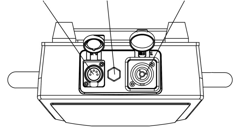
1 – Output lens 7 – Wireless indicator
2 – Head 8 – Battery button
3 – Yoke 9 – PowerCON TRUE1 input
4 – Control panel 10 – Mode / Esc button
5 – Base 11 – Up button
6 – Rubber feet 12 – Down button
13 – Enter button
14 – Optional wireless antenna
15 – 5 pin XLR DMX input
16 – 5 pin XLR DMX link out
17 – Vent valve
18 – PowerCON TRUE1 link out
14 EXO Beam 10 User Manual Rev. AGerman Light Products® Installation
4. Installation
Warning! Read ‘Safety’ starting on page 5 for important safety information
that you must understand before you install or operate the fixture. Install
EXO Beam 10 fixtures only as described in this chapter, or you may create
an installation that is unsafe.
Install the fixture at least 0.5 m / 20 in. away from combustible materials
(wood, textiles, paper, etc.), 0.5 m / 20 in. away from any surface that will
be illuminated, and a safe distance away from any flammable materials
(volatile spirits, etc.).
It is the installer’s responsibility to provide a stable, secure supporting
structure that is suitable for the environment and application and that
meets all applicable codes and legal requirements. Note the requirement
to secure lighting fixtures with safety cables in temporary installations.
Permitted mounting options
An EXO Beam 10 fixture may be installed in one of the following ways:
1. Fastened to a rigging truss or similar structure at any angle by means of
truss couplers or other clamps fixed to the two Omega brackets which attach
to the half-turn couplers on the underside of the base.
2. Standing upright on the base on a horizontal surface.
Securing fixtures with a safety cable
In temporary installations, if a fixture can cause injury or damage if it falls you must
secure it with a secondary attachment such as a safety cable that will hold it if the
primary means of attachment fails. The safety cable must be approved for the weight
that it secures. In multiple installations, each fixture must have its own safety cable.
EXO Beam 10 User Manual Rev. A 15www.glp.de Installation
To secure an EXO Beam 10 fixture with a safety cable:
Figure 3. Safety cable attachment
1. Loop a safety cable around a secure anchoring point such as a truss
beam or fixed structure so that it will catch the fixture if a rigging clamp fails.
Take up as much slack as possible in the safety cable (by looping it more than
once around the bar, for example).
2. See Figure 3 and Figure 4. Fasten the safety cable through the slot “B” on
the underside of the fixture base. Check that the fixture is now secured.
Installing on a rigging truss or similar structure
You can suspend an EXO Beam 10 fixture from a rigging truss or pipe using suitable
clamps attached to the Omega Brackets supplied with the EXO Beam 10.
If you are going to install the fixture hanging vertically downwards from a horizontal
rigging truss or pipe, you can fasten it to the truss using G-clamps. If you are going to
install the fixture in any other orientation, you must use half-coupler clamps that
completely surround the truss chord or pipe.
16 EXO Beam 10 User Manual Rev. AGerman Light Products® Installation
B
A A
Figure 4. Omega bracket fasteners
1. Attach suitable clamps to the Omega brackets.
2. Line up the fasteners of the Omega bracket with the holes “A” in the
base of the EXO Beam 10 as shown in Figure 4. The brackets may be installed
either way round so the cabling is in line with the bar or at right angles to it.
3. Lock the Omega brackets onto the EXO Beam 10 by turning the fasteners
through 90 degrees.
4. Attach the clamp to the truss or structure. Ensure that the head and yoke
of the fixture will not collide with any fixed objects as the fixture moves. Ensure
that the fixture has sufficient clearance to any adjacent surfaces or objects.
5. Secure the fixture with a safety cable through slots “B” as described in the
previous section.
Standing on a horizontal surface
To install an EXO Beam 10 fixture on a horizontal surface:
1. Check that the surface is secure and can safely hold the weight of the
fixture plus all hardware and cables.
2. Stand the fixture firmly on the rubber feet fitted to the base of the unit.
Ensure that the head and yoke of the fixture will not collide with any fixed
objects as the fixture moves. Ensure that the fixture has sufficient clearance to
any adjacent surfaces or objects.
EXO Beam 10 User Manual Rev. A 17www.glp.de AC mains power
5. AC mains power
Warning! Read ‘Safety’ starting on page 5 for important safety information
that you must understand before you install or operate the fixture.
Check that all cables and connectors are suitable for the installation
environment and application (see recommendations in ‘Avoiding damage
to the fixture’ on page 10).
Use H07 RN-F 3 x 2.5mm / SJT 12 AWG cables with original Neutrik powerCON
TRUE1 connectors to supply power to fixtures.
Line up the keyways in connectors carefully. Do not try to insert or twist a
connector if it feels excessively stiff. Resistance to insertion or twisting is a sign
that connectors may be incorrectly lined up.
Keep connectors sealed with their rubber caps at all times when not in use.
Included items
The EXO Beam 10 is supplied with a power cord with Neutrik powerCON TRUE1
connector.
Connecting to power
The AC mains power supply must include a connection to ground / protective earth. It
must be protected against ground / earth leakage and overload. The fixture’s internal
auto-sensing power supply accepts AC power at 100-240 V, 50/60 Hz. Do not connect
the fixture to power at any other voltage or to an external dimmer.
The EXO Beam 10 does not have a power ON/OFF switch. Power is applied to the
fixture as soon as the power cable becomes live.
The EXO Beam 10 has a 3-conductor Neutrik powerCON TRUE1 Mains IN power input
socket that accepts AC power from a TRUE1 female cable connector. Although TRUE1
connectors support hot plugging, it is still good practice to shut down power to power
cables before connecting them to fixtures.
To connect the fixture to power:
1. If convenient, shut down power to the power input cable.
2. Note the position of the keys and keyways on the TRUE1 power cable
connector and Mains IN socket and align them with each other. Insert the
cable connector into the socket and twist clockwise to lock. Do not use force.
If the connector feels excessively stiff, remove it and check again that it is
lined up correctly.
3. Before applying power to the power cable, check that nobody is looking
directly into the front of the fixture.
To disconnect the fixture from power, pull the latch on the cable connector outwards
to release it, then twist the connector counterclockwise and pull to remove it from the
socket.
18 EXO Beam 10 User Manual Rev. AGerman Light Products® AC mains power
Installing power connectors
If you intend to draw power from convenience receptacles / consumer mains power
sockets, it is possible to install a suitable cord cap / power plug on the supplied power
cord / input cable. If you do this, check that the cord cap / plug is rated minimum
250 V, 16 A, that it has a connection to ground / earth and that it has an integral cable
grip. Follow the cord cap / plug manufacturer’s assembly instructions.
If you need to install a Neutrik powerCON TRUE1 connector on a power cable, follow
the instructions given in the Support area of the Neutrik website at www.neutrik.com.
Respect the color coding used in the supplied power cable and in your local mains
power wiring system. US and EU systems use the color coding shown below:
Live or L Neutral or N Ground / Earth or
US system Black White Green
EU system Brown Blue Yellow/green
Connecting multiple fixtures to power in a chain
You can connect fixtures to power in a daisy-chain to simplify your power circuit
layout.
EXO Beam 10 fixtures have 2.5 mm2 internal wiring from Power IN to Power THRU
connectors.
Warning! Do not connect more than six (6) EXO Beam 10 fixtures in total to
power in one chain at 100-120 V, 60 Hz. Do not connect more than twelve
(12) EXO Beam 10 fixtures in total to power in one chain at 200-240 V, 50 Hz.
The power input cable supplied with the fixture is rated 16 A maximum. Add
together the maximum current draw ratings of all the devices that you
intend to connect to power in a daisy chain and do not create a chain with
a total maximum current draw of more than 16 A, or you will create a risk of
fire and electric shock.
To connect fixtures to power in a chain:
1. Obtain power relay cables that have male and female Neutrik
powerCON TRUE1 connectors. Cables must be minimum 14 AWG or 1.5mm2,
rated minimum 16 A and suitable for the environment and application.
2. Connect the power input cable to the Mains IN socket of the first fixture
as described under ‘Connecting to power’ on page 18.
3. Connect a relay cable to the Mains OUT / THRU socket of the first fixture
and to the Mains IN socket of the second fixture.
4. If you are using 100-120 V, 60 Hz AC mains power you can continue
linking EXO Beam fixtures Mains OUT / THRU socket to Mains IN socket until the
chain contains a maximum of six (6) fixtures in total. If you are using 200-240 V,
50 Hz AC mains power you can continue connecting fixtures Mains OUT to
Mains IN until the chain contains a maximum of twelve (12) fixtures total.
EXO Beam 10 User Manual Rev. A 19www.glp.de Connecting to DMX data
6. Connecting to DMX data
Check that all cables and connectors are suitable for the installation environment and
application (see recommendations in ‘Avoiding damage to the fixture’ on page 10).
Use digital 110 Ohm DMX cable with IP65 5-pin XLR connectors to supply DMX data to
fixtures.
Keep connectors sealed with their rubber caps at all times when not in use.
The EXO Beam 10 has two 5-pin XLR sockets for IN and THRU connections to a DMX
data link. EXO Beam 10 fixtures support the USITT DMX 512A signal protocol. They also
support RDM (Remote Device Management).
The 5-pin XLR connectors use standard pin allocations:
1 Signal Ground
2 Data –
3 Data +
4 Not used
5 Not used
The DMX cable should start at the console and be daisy-chained through each fixture
to be controlled using the DMX input and DMX link out connectors. If you need to split
the DMX cable, use a powered DMX splitter.
If you would like advice with planning and installing a DMX link, your GLP supplier will
be happy to provide assistance.
20 EXO Beam 10 User Manual Rev. AGerman Light Products® Starting and stopping operation
7. Starting and stopping operation
Warning! Before you apply power to the fixture or operate it after a
blackout, make sure that nobody is looking directly into the front of the
fixture.
The EXO Beam 10’s TRUE1 mains power input connector supports hot-plugging, and
connecting and disconnecting a live power cable is an option, especially if you need
to shut down power urgently, but it is still good practice to shut down power to the AC
mains power circuit before connecting and disconnecting power cables.
To start operation, check that nobody is looking into the front of the fixture, then apply
power to the AC mains power circuit.
To stop operation, shut down power to the AC mains power circuit.
EXO Beam 10 User Manual Rev. A 21www.glp.de Features
8. Features
The EXO Beam 10 unit has the following features:
Position
Pan rotation 630°(3.9 sec) or 540°(4.3 sec),Tilt rotation 267°(2.2 sec) with 16 bit
resolution. The fixture will automatically reposition if knocked – this option can be
disabled from the menu. The Pan and Tilt movements can be inverted using the menu.
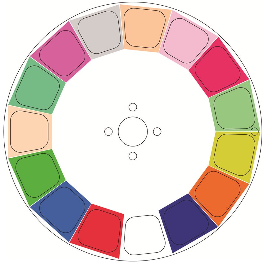
Color wheel
The fixture has a color wheel with 15 colors including open white. The wheel can snap
to full colors, be freely positioned for split colors and rotate in either direction at
variable speed.
1
2
15
3
14
4
13
5
12
6
11
7
10
8
9
Figure 5. Color Wheel
Color 01 – Open Color 09 – CTO 3200K
Color 02 – Primary Red Color 10 – CTC 6000K
Color 03 – Blue Color 11 – Pink
Color 04 – Primary Green Color 12 – Fern green
Color 05 – Amber Color 13 – Yellow
Color 06 – Cyan Color 14 - Orange
Color 07 – Magenta Color 15 – Dark blue
Color 08 – Cool white
22 EXO Beam 10 User Manual Rev. AGerman Light Products® Features
Gobo wheel
The gobo wheel has 15 positions including open. Seven of the gobos (the even
numbers in the diagram below) are rotatable and indexable, the others are fixed.
2
3 1
4 15
5 14
6 13
7 12
8 11
9 10
Figure 6. Gobo Wheel
Dimming
See Figure 7. You can select from two dimming curves using the control panel or the
Control / Settings DMX channel:
Linear Soft (Gamma)
Figure 7. Dimming curves
● Linear sets dimming so that it appears to increase and decrease evenly throughout
the dimming range.
● Soft gives finer control at low light levels and coarser control at high light levels.
EXO Beam 10 User Manual Rev. A 23www.glp.de Features The default setting is Soft. Strobe / shutter A variety of strobing and fading effects can be produced by the fixture. Prism Two separate prisms allow beam splitting effects. Each prism can be independently inserted in the beam path or removed, and can be continuously rotated in either direction or set to an indexed position. Behavior when the fixture is not receiving a DMX signal You can set the fixture to react in three different ways if no DMX signal is present (if the fixture is being controlled by DMX but the DMX signal stops, or if you apply power to the fixture when no DMX signal is present): ● Blackout sets the fixture to black out. This is the default setting. ● Hold sets the fixture to continue obeying the last DMX values it received. If no DMX signal was being received, the fixture will black out. ● Preset Scene sets the fixture to output a preset scene which you have previously captured from an incoming DMX state using the Manual Control > Capture Scene menu option. You can also manually set the control values (or edit the captured values) using the attribute settings in the Manual Control menu. All these settings are available via DMX on the Control / Settings channel and in the fixture’s control panel. 24 EXO Beam 10 User Manual Rev. A
German Light Products® Control menus and onboard display

9. Control menus and onboard display

           Warning! DMX control is disabled when the control menus are active. Be
           prepared for the fixture to emit strong light as soon as you exit the control
           menus.

The control panel and onboard LCD display provide access to user settings, readouts
and utilities.

                         W-DMX

                         Battery

                                    Mode         Down   Enter
                                           Up
                                    /Esc

                                   Figure 8. Onboard display

The four control buttons have the following functions:
      MODE/ESC: Activate the menus or go back one level towards the top of the
      menu.
      UP: Scroll up or increase a number.
      DOWN: Scroll down or reduce a number.
      ENTER: Activate the control panel if it is in sleep mode. Then enter a menu, select
      a setting or implement a command.
When you apply power to the fixture, it boots up. After it has booted, the panel
displays the default screen.
The Battery button is used to power up the control panel for setup before mains is
connected to the unit. Battery mode can be disabled in the menu.
The W-DMX indicator shows when wireless DMX is being received, if the optional
wireless module has been fitted.

EXO Beam 10 User Manual Rev. A                                                              25
www.glp.de Control menus and onboard display
DMX control is disabled when the control menus are active.
Display options
The illuminated LCD display lets you change fixture settings. The display has a battery
backup so that you can change the settings before mains is connected to the fixture.
See Chapter 9 for more details.
Using the Control / Settings DMX channel or the fixture’s control panel you can:
Set display modes using the Fixture Settings > Display Mode option:
- On: The display stays on constantly. This setting can be useful when you are
configuring or servicing the fixture.
- Auto: The display will automatically switch off after a few seconds even if the fixture
is not receiving a valid control signal or if it has detected an error.
Invert the display using the Fixture Settings > Display Orientation option, so it is easier to
read if the fixture is hanging upside down.
Display Locking
On the Fixture Settings > Lock menu, you can configure the display to lock after a
period of time to prevent accidental changes to the options.
You can set a custom lock code using the Fixture Settings > Lock > Set Passcode
option. If you do not set a custom code, the default code is 0000.
Manual Control
Using the Manual Control menu you can set fixed values to the fixture’s control
channels, as if it was in DMX control mode 1. This is useful when testing.
LED PWM frequency
The LEDs in the unit are dimmed using Pulse Width Modulation (PWM) which can
sometimes cause flickering on cameras. The Fixture Settings > PWM option allows you
to select different frequencies for the PWM to fix such issues. The higher frequencies
may cause reduced dimming performance.
Fan control
The fixture has internal cooling fans. In a noise critical situation you can slow these
down using the Fixture Settings > Fan Mode option. The normal setting is Regulated
which will adjust the fan speed automatically. If you set the option to Low the fan
speed is kept slow but this may result in the fixture overheating and reducing its output.
The fixture has an additional fan near the lens to clear condensation. You can control
how this fan works using the Fixture Settings > Defog option.
Fixture information
The Information menu in the control panel gives access to items of information from
the fixture’s sensors and memory. You can check temperature sensor readouts, see
total operating hours counters, and see software version number, for example.
26 EXO Beam 10 User Manual Rev. AGerman Light Products® Control menus and onboard display
Pan disable / Tilt disable
These options allow you to disable the startup reset movements or disable the drive of
the pan and/or tilt motors. The options are
- Off: Normal motor control
- Reset Disabled: The fixture will not do its power on reset sequence on this motor but
the motor is still controlled. This can be used when a fixture is mounted in a
confined space and would collide with an obstruction if it did the reset sequence.
- Current Disabled: The motor drive function is completely disabled. This is mostly
used for service or diagnostics.
Preset settings and factory defaults
You can store three different versions of option settings using the Service > Service
Advanced > Save Settings menu and load them using the Load Settings > Preset 1-2-3
options. These allow you to quickly set up the fixture in a particular configuration.
Settings are stored after a power off/on cycle and after a reset.
Two options are available in the fixture’s control panel for deleting multiple custom
settings and restoring defaults:
- Service > Default Settings reloads all the fixture’s factory default settings except
DMX address, DMX mode, captured scene, preset settings and offset values. This
option returns the fixture to baseline settings without affecting its basic
configuration in an installation.
- Service > Service Advanced > Factory Backup reloads all the fixture’s factory
default settings including DMX address, DMX mode, and erases all storage. This
option reinitializes the fixture completely and returns to its state when it left the
factory.
EXO Beam 10 User Manual Rev. A 27www.glp.de Control menu layout
10. Control menu layout
Menus Notes
DMX
1 - 512 Enter DMX address
ADDRESS
CONTROL
Standard – 15 channels Select DMX control mode
MODE
DMX Wired DMX control
CONTROL
PROTOCOL Wireless DMX control
WIRELESS
(optional module)
Pan Invert Off / On Invert Pan movement
Tilt Invert Off / On Invert Tilt movement
Reposition fixture if
Position Feedback Off / On
knocked
Off / Reset Disabled /
Pan Disabled
Current Disabled Disable motor drive for
Off / Reset Disabled / service
Tilt Disabled
Current Disabled
Zoom Invert Off / On Inverts Zoom movement
Dimmer Curve Soft (Gamma) / Linear Dimming curve
Blackout / Hold / run Action when no DMX
No Signal
Captured Scene signal
Press ENTER to capture
Capture Scene Store scene for no signal
scene
FIXTURE 600 Hz / 2200 Hz / 3000 Hz /
PWM Frequency of LED dimming
SETTINGS 4800 Hz / 9600 Hz / 25000 Hz
Display Mode Auto / On / Off Display blanking
Display Orientation Normal / Upside Down Display reversing
Sets overheat
Max Temperature 60 – 90C / 140-194F temperature where
shutdown will occur
Regulated / High / Medium
Fan Mode Set fan speed control
/ Low
Press ENTER for 3 sec to
Load Settings Preset 1 / Preset 2 / Preset 3
confirm
Lock Off / On /. Set Passcode Lock the control panel
Settings for lens defogging
Defog Off / On / Quick
fan
Disable the battery
Battery On / Off operation of the control
panel
MANUAL Press ENTER for 3 sec to
Reboot
CONTROL confirm
Manual function control Pan Coarse 0-255 These values can be set
(DMX Mode 1) manually or from a DMX
Pan Fine 0-255
state using Capture Scene
Tilt Coarse 0-255 option
Tilt Fine 0-255
Color Wheel 0-255
Gobo Wheel 0-255
Gobo rotation 0-255
Shutter 0-255
Dimmer 0-255
28 EXO Beam 10 User Manual Rev. AGerman Light Products® Control menu layout
Focus 0-255
Prism 1 0-255
Prism 2 0-255
Control 0-255
Press ENTER for 3 sec to
Capture Scene capture incoming DMX
state
Firmware Version ver x.x Fixture firmware version
Show fixture serial, RDM
Fixture Details Serial … xx / RDM … xx
unique ID
Shows power cycles,
Device Life Total / User
INFORMATIO Power Hours, LED Hours
N Refresh Rate (Hz) / Frame
DMX Link Status Details of DMX signal
Length / Mode Length
Temperatures xxx… Unit temperatures
Fan Speeds Fan1 …
Error Log Xxx
Press Enter to start test,
Test All Running
Menu or Enter to stop
Test Pan only Running
SERVICE Test Tilt only Running
Default Settings See Note 1 below
Hold Enter for 6 sec to
Service Advanced See below for menu
enter this menu
FACTORY
This menu is for use by authorized service technicians only
MENU
Note 1: Default Setting will return all options to default except DMX address, Control
Mode. It does not erase captured scene, preset settings or offset values
Default settings are written in BOLD type.
EXO Beam 10 User Manual Rev. A 29www.glp.de Control menu layout
Service Advanced menu
Hold down Enter for 6 seconds to access this menu.
Menus Notes
Pan Disable Off/On
Tilt Disable Off/On
Units °C / °F
Tilt xxx
Offsets
Zoom xxx
Power Hours
Power Cycles
Reset
LED Hours
Counter
Max Temperature
Temperature Unit
Preset 1
Save Settings Preset 2
Preset 3
Factory
See Note 2 below
Backup
Note 2: Factory backup will reset all options to default, erase captured scene, erase
preset settings, erase offset values. User Hour counter and Temperature Unit will not be
affected.
30 EXO Beam 10 User Manual Rev. AGerman Light Products® DMX control mode overview
11. DMX control mode overview
The EXO Beam 10 has only one DMX control mode which uses the following DMX
channels
Mode 1
DMX Mode 1: Standard Compact
The EXO Beam 10 uses 15 DMX 1 Pan
channels. 2 Pan fine
3 Tilt
It provides 16-bit control of pan and tilt, 4 Tilt fine
16-bit dimming and a shutter with 5 Color
strobe and ramp up/down effects. 6 Gobo
Control of the color wheel, gobo 7 Gobo Rotation
wheel, gobo rotation and the two 8 Shutter
prisms is provided. 9 Dimmer
10 Dimmer fine
You also have control of focus and a 11 Focus
control / settings channel that lets you 12 Focus fine
configure the feature and adjust 13 Prism 1
settings remotely via DMX. 14 Prism 2
15 Control / Settings
EXO Beam 10 User Manual Rev. A 31www.glp.de DMX control channel layout tables
12. DMX control channel layout tables
DMX Mode 1: Standard
11 DMX Channels
DMX Default
Channel Command range Percent DMX Fade
1 Pan
Pan left–right 0 65535 0 100 32767 Fade
2 Pan fine
3 Tilt
Tilt up–down 0 65535 0 100 32767 Fade
4 Tilt fine
Color 01 – Open 0 3 0.0 1.2 Snap
Color 02 – Primary Red 4 7 1.6 2.7 Snap
Color 03 – Blue 8 11 3.1 4.3 Snap
Color 04 – Primary Green 12 15 4.7 5.9 Snap
Color 05 – Amber 16 19 6.3 7.5 Snap
Color 06 – Cyan 20 23 7.8 9.0 Snap
Color 07 – Magenta 24 27 9.4 10.6 Snap
Color 08 – Cool white 28 31 11.0 12.2 Snap
Color 09 – CTO 3200K 32 35 12.5 13.7 Snap
Color 10 – CTC 6000K 36 39 14.1 15.3 Snap
5 Color wheel 0
Color 11 – Pink 40 43 15.7 16.9 Snap
Color 12 – Fern green 44 47 17.3 18.4 Snap
Color 13 – Yellow 48 51 18.8 20.0 Snap
Color 14 - Orange 52 55 20.4 21.6 Snap
Color 15 – Dark blue 56 59 22.0 23.1 Snap
Variable position 0-360°, split colors 60 167 23.5 65.5 Fade
Rotation clockwise fast > slow 168 211 65.9 82.7 Fade
Rotation stop 212 212 83.1 83.1 Fade
Rotation counterclockwise slow >
213 255 83.5 100 Fade
fast
6 Gobo wheel Open 0 2 0.0 0.8 0 Snap
Gobo 1 indexed 3 5 1.2 2.0 Snap
Gobo 2 6 8 2.4 3.1 Snap
Gobo 3 indexed 9 11 3.5 4.3 Snap
Gobo 4 12 14 4.7 5.5 Snap
Gobo 5 indexed 15 17 5.9 6.7 Snap
Gobo 6 18 20 7.1 7.8 Snap
Gobo 7 indexed 21 23 8.2 9.0 Snap
Gobo 8 24 26 9.4 10.2 Snap
Gobo 9 indexed 27 29 10.6 11.4 Snap
Gobo 10 30 32 11.8 12.5 Snap
Gobo 11 indexed 33 35 12.9 13.7 Snap
Gobo 12 36 38 14.1 14.9 Snap
Gobo 13 indexed 39 41 15.3 16.1 Snap
Gobo 14 42 44 16.5 17.3 Snap
Gobo 1 rotate 45 47 17.6 18.4 Snap
Gobo 3 rotate 48 50 18.8 19.6 Snap
Gobo 5 rotate 51 53 20.0 20.8 Snap
Gobo 7 rotate 54 56 21.2 22.0 Snap
Gobo 9 rotate 57 59 22.4 23.1 Snap
Gobo 11 rotate 60 62 23.5 24.3 Snap
Gobo 13 rotate 63 65 24.7 25.5 Snap
Gobo 1 shake and index 66 72 25.9 28.2 Snap
Gobo 2 shake 73 79 28.6 31.0 Snap
Gobo 3 shake and index 80 86 31.4 33.7 Snap
Gobo 4 shake 87 93 34.1 36.5 Snap
32 EXO Beam 10 User Manual Rev. AGerman Light Products® DMX control channel layout tables
Gobo 5 shake and index 94 100 36.9 39.2 Snap
Gobo 6 shake 101 107 39.6 42.0 Snap
Gobo 7 shake and index 108 114 42.4 44.7 Snap
Gobo 8 shake 115 121 45.1 47.5 Snap
Gobo 9 shake and index 122 128 47.8 50.2 Snap
Gobo 10 shake 129 135 50.6 52.9 Snap
Gobo 11 shake and index 136 142 53.3 55.7 Snap
Gobo 12 shake 143 149 56.1 58.4 Snap
Gobo 13 shake and index 150 156 58.8 61.2 Snap
Gobo 14 shake 157 163 61.6 63.9 Snap
Gobo 1 shake and rotate 164 170 64.3 66.7 Snap
Gobo 3 shake and rotate 171 177 67.1 69.4 Snap
Gobo 5 shake and rotate 178 184 69.8 72.2 Snap
Gobo 7 shake and rotate 185 191 72.5 74.9 Snap
Gobo 9 shake and rotate 192 198 75.3 77.6 Snap
Gobo 11 shake and rotate 199 205 78.0 80.4 Snap
Gobo 13 shake and rotate 206 211 80.8 82.7 Snap
Gobo 13 shake and rotate 164 170 64.3 66.7 Snap
Gobo wheel spin stop 212 212 83.1 83.1 Snap
Gobo wheel spin clockwise fast >
213 233 83.5 91.4 Fade
slow
Gobo wheel spin stop 234 234 91.8 91.8 Snap
Gobo wheel spin counterclockwise
235 255 92.2 100 Fade
slow > fast
when ch. 6 = “indexed”
0 Fade
Gobo index 0-360° 0 255 0 100
when ch. 6 = “rotate”
Gobo rotation stop 0 0 0 0
7 Gobo rotation
Gobo rotation clockwise fast > slow 1 127 0.4 49.8
0 Fade
Gobo rotation stop 128 128 50.2 50.2
Gobo rotation counterclockwise
129 255 50.6 100
slow > fast
Shutter closed 0 4 0 1.6
Single flash when change on dimmer
5 9 2.0 3.5
channel
Sync ramp up slow–fast 10 39 3.9 15.3
Sync ramp down slow–fast 40 69 15.7 27.1
8 Shutter Sync ramp up-down slow–fast 70 99 27.5 38.8 Snap
Sync double flash (slow–fast) 100 129 39.2 50.6 0
Random strobe pixel (slow–fast) 130 159 51.0 62.4
Random strobe all (slow–fast) 160 199 62.7 78.0
Sync strobe (1 Hz–10 Hz) 200 250 78.4 98.0
Shutter open 251 255 98.4 100
9 Dimmer
Intensity 0-100% 0 65535 0 100 0 Fade
10 Dimmer fine
11 Focus
Focus near to focus far 0 65535 0 100 32767 Fade
12 Focus fine
No prism 0 3 0 1.2
Variable position from 0-360° 4 127 1.6 49.8
Rotation stop 128 128 50.2 50.2
13 Prism 1 Rotation clockwise fast > slow 129 191 50.6 74.9 Fade
Rotation stop 192 192 75.3 75.3 0
Rotation counterclockwise slow >
193 255 75.7 100
fast
EXO Beam 10 User Manual Rev. A 33www.glp.de DMX control channel layout tables
No prism 0 3 0 1.2
Variable position from 0-360° 4 127 1.6 49.8
Rotation stop 128 128 50.2 50.2
14 Prism 2 Rotation clockwise fast > slow 129 191 50.6 74.9 Fade
Rotation stop 192 192 75.3 75.3
Rotation counterclockwise slow >
193 255 75.7 100
fast
No function 0 9 0.0 3.5
Dimmer curve: Extra-soft (3s hold) 10 15 3.9 5.9
Dimmer curve: Linear (3s hold) 16 21 6.3 8.2
Display mode: Auto (3s hold) 22 27 8.6 10.6
Display mode: On (3s hold) 28 33 11.0 12.9
Display mode: Off (3s hold) 34 39 13.3 15.3
Display orientation: Normal (3s hold) 40 45 15.7 17.6
Display orientation: Inverted (3s hold) 46 51 18.0 20.0
No DMX: Blackout (3s hold) 52 57 20.4 22.4
No DMX: Hold (3s hold) 58 63 22.7 24.7
No DMX: Stand-alone (3s hold) 64 69 25.1 27.1
Fan mode: Regulated (3s hold) 70 75 27.5 29.4
Fan mode: High (3s hold) 76 81 29.8 31.8
Fan mode: Medium (3s hold) 82 87 32.2 34.1
Fan mode: Low (3s hold) 88 93 34.5 36.5
Position feedback: Off (3s hold) 94 99 36.9 38.8
Position feedback: On (3s hold) 100 105 39.2 41.2
No function 106 117 41.6 45.9
Tilt inversion: Off (3s hold) 118 123 46.3 48.2
Tilt inversion: On (3s hold) 124 129 48.6 50.6
Control /
15 Pan inversion: Off (3s hold) 130 135 51.0 52.9 0 Snap
Settings
Pan inversion: On (3s hold) 136 141 53.3 55.3
Zoom inversion: Off (3s hold) 142 147 55.7 57.6
Zoom inversion: On (3s hold) 148 153 58.0 60.0
Defog: Off 154 159 60.4 62.4
Defog: On 160 165 62.7 64.7
Defog: Quick 166 171 65.1 67.1
Load Settings Preset1 172 177 67.5 69.4
Load Settings Preset2 178 183 69.8 71.8
Load Settings Preset3 184 189 72.2 74.1
PWM 600 Hz (5s hold) 190 195 74.5 76.5
PWM: 2200 Hz (5s hold) 196 201 76.9 78.8
PWM: 3000 Hz (5s hold) 202 207 79.2 81.2
PWM: 4800 Hz (5s hold) 208 213 81.6 83.5
PWM: 9600 Hz (5s hold) 214 219 83.9 85.9
PWM: 25 kHz (5s hold) 220 225 86.3 88.2
No function 226 231 88.6 90.6
Return to default settings 232 237 91.0 92.9
Reset Pan/Tilt (3s hold) 238 243 93.3 95.3
Reset Head (3s hold) 244 249 95.7 97.6
Reset All (3s hold) 250 255 98.0 100
34 EXO Beam 10 User Manual Rev. AGerman Light Products® Service
13. Service
Warning! There are no user-serviceable parts inside the fixture. Opening the
fixture can compromise its IP65 rating and cause damage that is not covered
by the product warranty. Any service operation that requires removal of a
cover must be performed by a professional service technician with the tools,
skills, and personal protective equipment to maintain high-powered lighting
equipment safely and efficiently.
Cleaning
EXO Beam 10 fixtures require occasional cleaning to prevent the buildup of dust, dirt, and
residue from atmospheric effects. Failure to keep the fixture clean will significantly reduce
light output and may cause heat buildup and damage that is not covered by the product
warranty. Regular cleaning will ensure maximum performance and reliable operation.
The cleaning schedule depends on the operating environment. Check fixtures regularly for
signs of dirt buildup.
You can clean the fixture using a soft cloth slightly dampened with a household or
automotive glass cleaning product. Do not apply pressure to the clear front or display on
the back of the fixture, as you may scratch these surfaces.
GLP Service and Support
Contact information for the nearest GLP Service and Support is available online at
www.glp.de/en/service, by email at info@glp.de, or by telephone at the following
numbers:
● GLP Germany: +49 (7248) 927 19-55
● GLP N. America: +1 818 767-8899
● GLP UK: +44 1392 690140
● GLP Asia: +852 (3151) 7730
● GLP Nordic: +46 737 57 11 40
EXO Beam 10 User Manual Rev. A 35You can also read