Low Voltage Surge Protection - Australia & New Zealand - SPD Product Catalogue 2010 - Eaton
←
→
Page content transcription
If your browser does not render page correctly, please read the page content below

SPD Product Catalogue 2010

Low Voltage
Surge Protection
Australia & New Zealand

Low Voltage Surge Protection
   Understanding Surge Protection & it’s Applications

  Why do I need surge                Are there any standards that       be used in conjunction with        2. Control current flow to the
  protection?                        apply?                             local electrical switchboard       next zone.
  If a surge is of sufficient        For many years now there           & wiring codes. Some of the
  energy level then it can           have been internationally          standards that apply & are         Do it again!
  damage or destroy electrical       recognised standards               often mentioned are:
  equipment or even the              for surge & lightning risk                                            1. Divert excess residual
  electrical infrastructure          assessment & protection.           • IEC LV Framework                 energy.
  itself. Direct & indirect costs    Research & standards
  to a business can be very          committees publish many            • ANSI / IEEE C62.41              2. Control current flow to the
  expensive. A surge protection      standards relating to surge           Waveform, test & current        next zone.
  device is in real terms very in-   risk & immunity. These                standards & limits.
  expensive & when correctly         standards however differ from                                         It’s that simple. However,
  selected & installed can           one geography to another.          • AS/NZS1768 Lightning &          understanding what the
  prevent damage occurring.          Of importance is that there           Surge Protection - Risk         correct risk rating is, what
                                     are two basic low voltage             assessment.                     needs to be protected vs. what
  What is a surge?                   standards in the world. In the                                        does not, what product to use
  A surge is a random, short         U.S. it is 120Vac, 60Hz. ( half    • IEC61643, UL1449 Equipment      & how to correctly install it for
  burst of excess electrical         the voltage & twice                   standards                       full performance benefit can
  energy to a system. It is          the current ). In Europe,                                             be difficult. By following the
  typically measured in micro &      Australasia & parts of Asia it     • IEC 61006-1,2,3,4               next few pages we make it
  milli-seconds. Also referred       is 220-240Vac, 50Hz. ( twice          EMI/RFI generation &            easier to identify risk, classify
  to as a transient, impulse         the voltage, half the current         immunity                        protection zones & identify
  or spike, these electrical         ). It is important to recognise                                       suitable products.
  disturbances can damage            that there are differing           And that’s not all of them.
  or even destroy sensitive          methodologies & compliance         There’s a lot to understand.       What are the rules for
  microprocessor-based               regulations for both systems.                                         installation?
  equipment. Surge protection        There are similarities between     Some standards overlap, it is      One of the key issues often
  devices are designed to            the US & European standards,       easy to confuse them & apply       overlooked is the correct
  reduce the amount of harmful       but at key points the standards    an in appropriate standard.        placement & installation
  energy that flows into a           become mutually exclusive.         Understanding the standards        practice that should be
  system.                                                               is key to success.                 applied. Each site is different.
                                     So what standards do I use?                                           There is no single definitive
  Where do they come from?           Our electrical infrastructure in   System design                      design that can be applied
  80% of transients are              Australia has been developed       System design is not as            across the board for all surge
  generated from internal            based on European standards.       difficult as it seems. As long     protection situations. It very
  sources such as load               It is therefore appropriate to     as the basic principles of         much depends on the specific
  switching, motors starting         use the European standards         applicable standards are           site infrastructure. There are
  up or even turning on air          as our guide. There are            applied then the job at hand       however, some basic rules
  conditioning systems. The          many surge standards that          is to:                             that should be practiced to
  other 20% of transients are        can be followed. Most AS/                                             ensure that a solution will
  typically generated from           NZS standards have great           1. Divert the incoming excess      work effectively. Whilst not
  external sources such as           similarity to the IEC standards.   energy at the point-of-entry.      comprehensive, the following
  lightning strikes & power          There are several levels of        (Stop it BEFORE it gets into the   are guidelines for successful
  company grid switching. Like it    standards that can apply to        system. It’s cheaper & easier      installation.
  or not, most electrical systems    any solution. It is important      to deal with it at the point of
  are subjected to some level of     to understand that there is a      entry).
  transients.                        hierarchy of standards. At the
                                     highest level there are the Low
  What is SPD?                       Voltage Framework Directives.
  Referred to as Surge               Below this are Lightning
  Protection Device (SPD). They      & Surge Risk Assessment
  are defined as:                    standards. Below this again
  “A device designed to protect      are TVSS & SPD equipment
  electrical equipment from          standards & within these are
  power surges & voltage             test & waveform standards.
  spikes.”                           All these standards need to

2 Eaton Surge Protection
Physical & electrical location.       rising transients. For medium       0.5m on any cable & always         to the load with the potential
Location, Location, Location.         & high-current services              tie cables tightly together.      to damage the load instead
It’s a familiar line but very true.   (250-3000A), use the maximum        Try to keep surge voltage          of being diverted to the main
Getting the location of an SPD        fuse as recommended by the          drop to

Selecting Surge Protection Equipment
   Understanding Surge Protection Categories

    Protection Categories                                                       to neutral or earth, protecting switchboards, contactors,
                                                                                transformers & motors from burnout due to extreme voltages.
                                                                                A properly installed surge diverter can limit surges to below
     Surge Protection Zones (ANSI/IEEE C62.41)                                  2000V.

                    Cat E      Cat D         Cat C      Cat B         Cat A     If the main load in an installation is critical of high voltages
                   6kV/70kA   6kV/30kA      6kV/15kA   6kV/3kA       6kV/200A
                                                                                (computers, communications systems, test equipment etc.), or
                                                                                generates electrical noise (variable speed motor drives,
                                                                                high-frequency welders etc.), a Surge/Power Filter (PPFI)
                                                                                should be used. In an PPFI, surge diverters are utilised in
                                                                                conjunction with low-pass filtering to reduce the surge voltage
                                                                                & remove noise. In normal operation, an PPFI can be expected
         TELECOM
                                                                                to reduce surge potentials to less than 1000V whilst providing
          TOWER
                                                                                up to 70dB of noise attenuation.
                                OUT
                              BUILDING
                                                                                Method
                                                                                Firstly determine whether or not you require filtering or just
                                  SERVICE
                                 ENTRANCE
                                                       RESIDENTIAL
                                                        BUILDING                surge diversion. If selecting a surge diverter, select a device
                                                                                appropriate for the protection category. The MSDI & SPDI are
                                                                                suitable for category C & B locations. Quickmov surge diverters
                                                                                can also be used in these locations for protection of Quicklag
                                                                                & DIN panelboards.
   Eaton manufactures a complete range of power protection
   components. These components fall into a number of                           If the site requires filtering at the point of entry, select an PPFI
   categories, depending upon where they are utilised in an                     with the appropriate current rating for the load, then select the
   electrical installation. The 3 main categories are, according to             model appropriate for the protection category.
   ANSI/IEEE C62.41 & AS/NZS1768-2007:
                                                                                For DC solar panel arrays with Grid Interactive inverters it is
   Category A (6kV/200A): Long final sub circuits & power outlets               recommended that Cat C / Class II, DC type SPD’s are used.
   Category B (6kV/3kA): Major sub mains & short final sub circuits             For this situation the PVD40 series Photo Voltaic Diverters in
                                                                                500, 600 and 1000vdc versions be used.
   Category C (6kV/15kA): Point of entry
                                                                                Minor sub mains & short final sub circuits – Class II/Category B
   In addition to these categories, there are 2 more categories
                                                                                Once past the main board, most protection involves both
   which simply extend the Category C rating:
                                                                                surge diversion & filtering. Non-critical loads such as lighting
   Category D (6kV/30kA): Point of entry, high exposure                         & general-purpose power circuits do not necessarily require
                                                                                protection.
   Category E (6kV/70kA): Point of entry, very high exposure
               & critical load
                                                                                Method
   Equipment listed in this catalogue is referenced by category to              For large 3-phase loads such as mainframe computers or
   make the selection of correct components easier.                             computer-controlled machinery, select an PPFI appropriate for
                                                                                the load. In this case the protection level required is usually
                                                                                taken as ‘one step’ below the protection level applied to the
    Selecting Surge Protection Equipment for Commercial                         point of entry. For single-phase loads up to 63A, the DSFI &
    & Industrial Applications                                                   MSFI filter ranges are suitable (for current < 25A, the CSFI
                                                                                filter also provides installation compatibility with modular
                                                                                switchboards). Generally, filters should be mounted as close as
   High risk direct strike or point of entry. Class I/Cat D & E                 possible to the equipment being protected.
   For very high risk installations it is recommended that Class I
   type SPD’s are used. Such devices are commonly referred to
   as “Spark gap arresters “. For this situation the SPDSG50-300
   should be used for L-N and L-E modes and the SPDSG50-255NPE
   should be used for N-E mode.

   Point of Entry – Class II/Category C
   Basically, all installations should at least be protected at the
   point of entry. The starting point for protection is the surge
   diverter. Surge diverters effectively clamp the incoming lines

4 Eaton Surge Protection
Long Final Sub circuits & Power Outlets - Class III/                   If the site requires filtering at the point of entry, select a DSFI
Category A                                                             filter with the appropriate current rating for the load. The DSFI
When protecting final sub circuits & power points there are 2          filter is rated at 5-32A (for current < 25A, the CSFI filter also
options. Either fit hard-wired filters to the circuit or use plug-in   provides installation compatibility with modular switchboards).
filters on the equipment to be protected. This choice will be
determined by the load (plug-in filters are only rated up to 10A),     Final Sub circuits & Power Outlets – Class III/Cat A
& whether or not there is space for a plug-in filter adjacent          When protecting final sub circuits & power points there are 2
to the equipment. With large computer networks, many                   options. Either fit hard-wired filters to the circuit or use plug-in
administrators prefer not to use plug-in filters as they can be        filters on the equipment to be protected. This choice will be
accidentally unplugged by the operator’s foot, causing network         determined by the load (plug-in filters are only rated up to 10A),
problems. For small servers however, a plug-in filter provides         & whether or not there is space for a plug-in filter adjacent to
extra protection at the computer for ‘insurance’.                      the equipment. Generally, a plug-in filter, used in conjunction
                                                                       with protection at the switchboard, gives the best protection.
Method
Firstly select whether a hard-wired or plug-in filter is to be         Method
used. If selecting a hard-wired filter, the DSFI range is suitable     Firstly select whether a hard-wired or plug-in filter is to be
for currents up to 32A (for currents < 25A, the CSFI filter also       used.
provides installation compatibility with modular switchboards).
                                                                       If selecting a hard-wired filter, the DSFI is suitable for currents
For plug-in filters, the SSFI series provides high levels of
                                                                       from 5 to 32A (for currents < 25A, the CSFI filter also provides
protection with good filtering.
                                                                       installation compatibility with modular switchboards).
                                                                       For plug-in filters, the SSFI & POD provides high levels of
                                                                       protection with good filtering. The POD also provides protection
Selecting Surge Protection Equipment for Domestic                      for ancillary devices such as phone/fax, network & coaxial
& Home-office Applications                                             cables - ideal for protecting video TV systems in domestic
                                                                       applications.
Point of Entry – Class II/Cat C, B                                     Note: cable systems are electrically referred to mains neutral
As with commercial & industrial applications, all installations        which only increases the potential of damage from electrical
should at least be protected at the point of entry. Again, this        faults. If high levels of filtering are required such as for home
usually involves the use of surge diverters. Surge diverters           automation or high-end audio visual, or other noise-critical
effectively clamp the incoming lines to neutral or earth,              equipment, the sub circuits supplying these systems should be
protecting the switchboard & wiring from damage due to                 protected at the switchboard by a high level device such as the
extreme voltages.                                                      CSFI.
Surge diverters are a ‘must’ if the building is located in an
exposed position or fed by long aerial cables, as in rural
installations. If the building is part of a medium or high-density
development & is fed by an underground cable, the risk of high-         Selecting Surge Protection for Dataline Applications
energy surges is quite low. In these cases, a surge diverter may
not be necessary.
                                                                       For IT & telecommunication applications, dataline network
                                                                       protectors provide further protection against transients which
In most domestic buildings, the main switchboard is the only           can enter the electrical system through “back-doors”. The
switchboard & therefore, if it is desired to provide filtered          EMTJ & ERAK series offer transient protection for single port or
power for critical applications such as computers, office              multi-port configuration on CAT5 & CAT6 networks. The SF8RM
equipment or entertainment systems, this should be done on             is designed for surge protection in data rack cabinets where
the main switchboard. Few domestic applications use 3-phase            space is typically limited.
power & those that do usually only use it for heating or air-
conditioning. For this reason, only the phase supplying power to       For twisted pair coms and signalling data line it is
critical equipment is actually filtered. The remaining phases are      recommended that Cat A / Class III type SPD’s are used. For
simply fitted with shunt diverters.                                    this situation the SPD-DM series diverters in 5, 12, 24 or 48vdc
Method                                                                 versions be used.
Firstly determine whether or not you require filtering or just
surge diversion. If selecting a shunt diverter, select a device
appropriate for the installation. The SPD3NI, SPD3GI, SPDV60 &
SPDT60 are suitable for single & multi-phase installations whilst
the SPD120I is ideal for very exposed sites (on hilltops or with
long aerial cables).

                                                                                                                     Eaton Surge Protection 5
Direct Strike Protection
         Class I/Category D & E (6kV/30kA)

6 Eaton Surge Protection
Eaton® SPDSG Series
Class I/Cat D & E Spark Gap & GDT Diverter

                                                                                               multiple gap element design to ensure accurate
                                                                                               triggering & with no follow current. There are 2 models
                                                                                               to choose from. The SPDSG50-300 is suitable for
                                                                                               connection across L-N or L-E. The SPDSG50-255NPE is
                                                                                               suitable for connection in common mode across N – E.
                                                                                               Each have been tested to the stringent requirements of
                                                                                               10/350us waveform standard , commonly known as I imp,
                                                                                               & exhibit exceptionally low let through voltage of less
                                                                                               than 2.5kV at 50kA.

                                                                                                   Specifications
                                                                                               •    1 mode protection. N-E, L-E or L-N
                                                                                               •    50kA surge suppression rating
                                                                                               •    Compact modular solution
Shunt Surge Diverter                                                                           •    2 unit DIN43880 case, 36mm DIN-rail mount
3 Phase, 100-400A, 80-240kA
                                                                                                   Applications
The new SPDSG series diverters are designed as IEC                                             • Direct strike point of entry locations.
61643-1, Class I, direct strike, surge diverters to protect
high risk installations. Typically known as spark gap                                              Key Features:
devices, these diverters use the latest technology

 Technical Specifications                                    SPDSG50-300                                            SPDSG50-255NPE

 Technology                                                  Encapsulated Spark Gap                                 Encapsulated Gas Arrester

 Method of mounting                                          35mm Din rail                                          35mm Din rail

 Input voltage (Un)                                          230vac nominal                                         230vac nominal

 Max Continuous Voltage (Mcov)                               300vac                                                 255vac

 Test classification IEC                                     Class I                                                Class I

 Maximum rated surge current –                               50kA                                                   50kA
 (I imp) 10/350us

 Max rated surge current – (Imax) 8/20us                     140kA                                                  140kA

 Residual voltage (Vpl)
Point of Entry Protection
         Class II/Category C (6kV/15kA)

8 Eaton Surge Protection
Eaton® PPFi
Class II/Cat C & D
3 Phase Premium Power Filter
                                                         The PPFI is designed to provide point-of-entry (Category
                                                         C) & sub-circuit protection (Category B) against power
                                                         surges caused by external sources such as lightning strikes
                                                         & substation switching as well as providing a measure of
                                                         protection from surge events generated on the secondary side
                                                         of the filter. An ideal device for all Category locations.

                                                         The PPFI is a 3-stage protection system utilising primary &
                                                         secondary MOV protection in conjunction with a Low-Q LC
                                                         filter. The unit provides filtering of the line harmonics, noise
                                                         & RF transmitters with a cut-off frequency of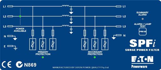
Eaton® PPFI
    Specifications

     Technical Specifications                                                    PPFXXX3CEi                              PPFXXX3DEi                             PPFXXX3EEi
     Input voltage                                                               380 - 440VAC 3 Phase

     Maximum continuous voltage – MCOV                                           300VAC L-N

     Temporary overvoltage - TOV                                                 320VAC, 15 mins

     Service type                                                                TT, TN, TN C-S or any 3-phase system with a grounded neutral. This unit must not be connected to an ungrounded
                                                                                 system

     Test classification                                                         Class II

     Energy Absorption rating - per mode (Joules)

     Primary protection L-N:                                                     1,200J/ph, 3,600J total.                1,800J/ph, 5400J total.                3,600J/ph, 10,8000J total.
     Secondary protection L-N:                                                   600J/ph, 1,600J total.                  600J/ph, 1800J total.                  600J/ph, 1,800J total.
     Common mode protection N-E:                                                 2,130J.                                 710J.                                  710J.
     Aggregate rating:                                                           7,530J.                                 7,910J.                                13,310J.

     Current rating – continuous (standard                                       100A, 160A, 200A, 300A, 400A
     models)

     Recommended maximum over current protection                                 100A, 160A, 200A, 300A, 400A

     Residual current
Eaton
Eaton
®
®PPFI
PPFI
Block Diagram & Mimic Display
Surge Category 1 Mode Multi-Element Series Filter
2 Mode 2 Stage Surge Diverter
The PPFI is suitable Primary
MOV
High
Frequency
Series
Blocking
High
Frequency
Secondary
MOV
Protection Protection
for use in all category Capacitor Inductor Capacitor
locations:
Normal Normal
Mode Mode
Class II/Cat D
(6kV/30KA) Point of Power
Input
Power
Output
Entry, High Exposure
UL1283
Common Mode EMF/RFI Common Mode
Filter Block
Class II/Cat C
(6kV/15kA) Point of
Entry/ Service Entrance
SPFXXX3CEi Block Diagram
Class II/Cat B 1 Mode Multi-Element Series Filter
(Special Applications) 2 Mode 2 Stage Surge Diverter
Primary MOV Secondary MOV
(6kV/3kA) Major sub High Series High
Protection Frequency Blocking Frequency Protection
Capacitor Inductor Capacitor
mains & short final sub
circuits
Normal Normal
Mode Mode
Power Power
Input Output
UL1283
EMF/RFI Common Mode
Filter Block
SPFXXX3DEi & SPFXXX3EEi Block Diagram
Eaton Surge Protection 11CMY
CY
MY
CM
K
Y
M
C
Eaton® PPFI
Connection & Line Diagram
F i S urge F ilter
nec tion Diagram
Min dis tance
1003C E i, S P F 1003DE i, S P F 1003E E i, to ceiling 300mm
50C E i, S P F 150DE i, S P F 150E E i,
00C E i, S P F 200DE i, S P F 200E E i, OUT P UT/LOAD
250C E i, S P F 250DE i, S P F 250E E i
L1 L2 L3 N
ument is to be us ed in c onjunc tion with LOAD
S urge F ilter Ins tallation G uide
(T vs s Doc #510063)
Earth
eutral connections via 8mm bolts.
n via M8 s tud, lower right of enclos ure.
g for connection points.
parate earth cable, even if the unit is bolted to L1 L2 L3 N
output cables phys ically separated at all times. E Earth Stud
dis tance 500mm. INP UT/S UP P LY On G ear T ray
preferred to MC B s for connection to main S W B . 8mm
ns tallation guide for details.
ted within 3m (cable length) of the main system
al link for point-of-entry application. G reater
protection.
proper operation of this S P F it is essential that
Min distance
ys ically s hort earth connection be made to the to floor 600mm
nt. W ith reference to local wiring standards,
us ually s ized agains t a thermal rating,
xpected fault currents , (5,000 to 25,000 amps).
an S P F however, the installer must be aware
nts can exceed 50,000 amps, and therefore
CMY
CY
MY
CM
K
Y
M
C
re generally required to limit voltage drops MAIN
ditions . T o achieve these requirements, the
s hould be s elected to be equal to, or greater
MAIN S WB E AR T HING
POINT (S W B )
incoming cable into the S P F . T his ensures that Important: Before installing the
n the earth cable are minimis ed. device, please read & follow the instal-
power-carrying conductors s hall be s ized
a lly-applicable s tandards. It is recommended
lation & operation instructions.
g neutral conductor be sized the same as (or
phas e conducts as it is the primary return for
es. 1 2 3 4
D 3/2/2005 S P F i S eries D
Differential protection and filtering. 550193
3/2/2005 LC
One phase shown, all phases identical
LINE IN LINE OUT
FPRI FILTER BLOCK FSEC
C C
L-N protection L-N protection
NEUTRAL IN NEUTRAL OUT
N-E protection
NO
B B
DIN-ADD SPF COM ALARM OUT
Display Driver Display PCB
NC
EARTH STUD
Common-mode
protection.
FROM OTHER PHASES
Title
A A
SPF FILTER LINE DIAGRAM
Size Number Revision
A4 550246 0
12 Eaton Surge Protection Date: 7-Aug-2006 Shee1t of1
JDP
File: C:\tvss engineering\Product_engineering\current\MSF\MSF.ddb
Drawn By:
1 2 3 4Eaton® MSDI
Class I & II/Cat D & C
Three Phase Surge Diverter
The MSDI surge diverter is designed to provide point-of-entry
protection against power surges caused by external sources
such as lightning strikes & substation switching. Common-mode
protection is available for sites remote from the M.E.N. point
including industrial sites & rooftops in multi-storey
buildings. An ideal device for all Category locations.
The MSDI surge diverters utilise MOV protection for both
differential & common-mode protection. Multiple MOV devices
are used in parallel for primary circuit redundancy. The status of
protective devices is continuously monitored & displayed using
LED bar-graph indicators. All MOV devices are thermally fused
& isolated by ceramic fuses.
Shunt Surge Diverter, 3 Phase 200kA MSDI unit is provided with an alarm relay. The alarm function
provides a summary alarm output for protection degradation as
Typical applications:
well as power failure. The alarm may be configured to indicate
either partial or total protection failure. The level of protection
• All Power Circuits including "Point-of-Entry"
remaining is indicated by LED bar-graph indicators on the front
• Telecommunications Systems & Rectifiers
panel. A summary alarm relay contacts provide remote
• Process & Control Systems & UPS Systems
signalling to remote equipment.
• Computer & Medical Systems
• Multi-storey buildings
• All sensitive Electronic Equipment
Key Features:
• 3 Mode, 2 Stage Surge Diverter
• Surge suppression rating of 200kA
• Enclosed in IP24 cabinet
• LED Bargraph display on each phase
• Protection Fail Alarm Relay
• 5 Year Warranty
Surge Category 3 Mode 2 Stage Surge Diverter
The MSDI is suitable Primary
MOV
Secondary
MOV
for use in category Protection Protection
locations:
Class II/Cat D Normal
Mode
Common Mode
(6kV/30KA) Point of Power Power
Entry, High Exposure Input Output
Class II/Cat C Common Mode
(6kV/15kA) Point of
Entry/ Service Entrance
MSDi Block Diagram (Only 1 phase shown, all phases are identical)
Eaton Surge Protection 13Eaton®® MSDI
Eaton MSDI
Specifications
Technical Specifications MSD200CM60i
Input voltage 200 - 250VAC (380 - 440VAC 3 Phase)
Maximum continuous voltage (MCOV) 320VAC
Temporary overvoltage - TOV 350VAC, 15 mins
Service type TT, TN, TN C-S or any 3-phase system with a grounded neutral
Energy Absorption rating - per mode (Joules) Primary Protection L-N = 3,000J/ph, 9,000J total
Common mode protection L-E = 710J/ph, 2,130J total
Common mode protection N-E = 2,130J total
Aggregate rating 13,260J
Recommended max. overcurrent protection 125A GL HRC fuse
Protection modes Line-Neutral, Line-Earth, Neutral-Earth
In 8/20us (Line-Neutral) Nom. surge life 75kA per phase x 20 times
In 8/20us (Line-Earth) Nom. surge life 15kA per phase x 20 times
In 8/20us (Neutral-Earth) Nom. surge life 45kA x 20 times
Ismax 8/20us (Line-Neutral) Max. surge life 200kA
Ismax 8/20us (Line-Earth) Max. surge life 40kA
Ismax 8/20us (Neutral-Earth) Max. surge life 120kA
Initial clamp voltage (Line-Neutral) 560V (350Vac RMS)
Initial clamp voltage (Line-Earth) 680V (420Vac RMS)
Initial clamp voltage (Neutral-Earth) 680V (420Vac RMS)
Internal protection (fusing) All surge diverter connections are fused via HRC fuses to IEC269-2-1
Alarms/indicators Bargraph display for protection remaining, dry contact alarm relay output – 250Vac/32Vdc, 10A, 4kV
isolation, Alarm under-voltage cutoff 180Vac.
Enclosure rating IP24
Design Standards: IEC61643-1, IEC610006-1,2,3,4 ANSI/IEEE C62.41 Cat B,C,D,E AS1768-2007 Cat B,C,D,E AS3000,
AS3100, CE mark
Dimensions & Weight 370 x 160 x 560 mm (W x D x H), 14kg
Environment -10 to 65°C, 10 to 90%RH (non-condensing)
Due to continual product improvement specifications are subject to change without notice. Copyright 2010 Eaton Corporation.
CMY
CY
MY
CM
K
Y
M
C
CMY
CY
MY
CM
K
Y
M
C
Connection & Line Diagram
550192_msdi_cnx_dia_a4.pdf 6/10/2008 1:30:27 PM
1 2 3 4
S urge Diverter
Min distance D D
c tion Diagram to ceiling 300mm
Differential protection.
One phase shown, all phases identical
t is to be us ed in c onjunc tion with LINE
Diverter Ins tallation G uide T O LOADS FPRI
vs s Doc #510065)
C C
L-N protection
connections via 8mm bolts .
M8 s tud, lower right of enclos ure. INP UT
connection points . F US E
e earth cable, even if the unit is bolted to L3 L2 L1 N
t cables phys ically s eparated at all times. E E AR T H S T UD
nce 500mm. ON C AS E
red to MC B s for connection to main S W B . 8mm NEUTRAL
ation guide for details . L3
within 3m (cable length) of the main s ystem
k for point-of-entry application. G reater N-E protection L-E protection
L2
ction.
per operation of this MS D it is es s ential that NO
Min distance
ly s hort earth connection be made to the L1 Protection alarm
ith reference to local wiring standards, to floor 600mm B
COM
B
ally s ized agains t a thermal rating, NE UT R AL LINK
ted fault currents , (5,000 to 25,000 amps). OR
S D however, the ins taller mus t be aware
M.E .N. NC
an exceed 50,000 amps, and therefore
nerally required to limit voltage drops MAIN S W B EARTH STUD
ns . T o achieve these requirements, the Common-mode protection.
ld be s elected to be equal to, or greater
ming cable into the MS D. T his ensures that
One phase shown, all phases
earth cable are minimis ed. < 3m line distance identical
er-carrying conductors s hall be sized MAIN FROM OTHER PHASES
pplicable s tandards . It is recommended E AR T HING
P OINT (S W B )
utral conductor be s ized the same as (or
e conducts as it is the primary return for Important: Before installing the device,
please read & follow the installation & A
Title
MSD LINE DIAGRAM
A
operation instructions. Size
A4
Number
550250
Revision
0
2/23/2005 MS Di S eries Date: 7-Aug-2006 Shee1t of1
File: JDP
C:\tvss engineering\Product_engineering\current\MSF\MSF.ddb
Drawn By:
550192
2/23/2005 LC 1 2 3 4
14 Eaton Surge ProtectionEaton® SPDI Series
Class I & II/Cat D, C & B
Din Rail Mounted Surge Diverters
Key Features:
• Surge ratings starting from 40kA up to 100kA (8/20uS)
• DIN43880 profile IP20 enclosure allows compatibility with most
common switchboards
• Versatile mounting clips offer the option of DIN rail or surface
mount with ease
• Clear & concise protection status indicators &
a dry-contact alarm
• Extended voltage range to suit most common power
distribution systems
Shunt Surge Diverter, 1 & 3 Phase, 40kA & 100kA
Eaton's SPDI surge diverters provide the ultimate solution for surge protection in single & multi-phase systems. Whether the
application involves residential homes, telecommunication facilities, hospitals, schools or heavy industrial plants, the SPDI surge
diverters provide protection against the damaging effects of lightning, utility switching, switching electric motors & more. SPDI surge
diverters can be installed as point-of-entry or sub-board protection & are connected in parallel with the power circuit via separate
protection HRC fuses. These devices are ideal for Category C & B locations.
1 Mode (L-N) 1 Stage Diverter
MOV
Protection
Normal Mode
Power Power
Input Output
Class I/Cat D SPD120i Block Diagram
The SPD120I is designed to protect single-phase power systems against surges & spikes caused by lightning strikes & other electrical
sources. The unit is intended for point-of-entry or main board protection in medium to high exposed locations. SPD120I are easily
configured for L-N or L-E protection for installations adjacent or remote from the M.E.N. link, which means it can provide protection
for commercial buildings to rural sites.
Eaton Surge Protection 15Eaton® SPDI Series
Class II/Cat C & B
Din Rail Mounted Surge Diverters
Applications:
• Ideal for Point of Entry or Sub-board Protection
• Telecommunication Systems & Rectifiers
• Process & Control Systems
• Computer Systems
• Medical Systems
• All Sensitive Electronic Equipment
Class II/Cat C & B
The SPD3NI is designed to protect 3-phase power systems against damage from surges & spikes caused by lightning & other
electrical sources. The unit is intended for point-of-entry or sub-board protection in low to medium exposed locations adjacent to the
M.E.N. link. For protection in locations remote from the M.E.N. link use a SPD3GI Gas Arrestor model.
2 Mode 1 Stage Surge Diverter Surge Category
L1 MOV L2 MOV L3 MOV
Protection Protection Protection
L1 L1
Normal
Mode
The SPDI is suitable for use in
L2
Normal
Mode L2
category locations:
Power Power
Input
L3
Normal
Mode L3
Output
Class II/Cat D
N N (6kV/30KA) Point of Entry, High
Common Mode Exposure (SPD120I Only)
E E
Class II/Cat C
SPD3Ni Block Diagram (6kV/15kA) Point of Entry/ Service
Entrance
Class II/Cat B
2 Mode 1 Stage Surge Diverter
(6kV/3kA) Major sub mains & short
L1 MOV
Protection
L2 MOV
Protection
L3 MOV
Protection final sub circuits
L1 L1
L2 L2
Common
Power Power
Mode
Input Common Output
L3 Mode L3
Common
Mode
N Common N
Mode
E E
SPD3Gi Block Diagram
16 Eaton Surge ProtectionEaton® SPDI
Specifications
Technical Specifications SPD120I SPD3NI SPD3GI
220-277VAC (380-480V) 220-277VAC (380-480V) 220-300VAC (380-520V)
Input voltage
40-70 Hz 40-70 Hz 40-70 Hz
Maximum continuous operating voltage (MCOV) 320VAC 350VAC
Temporary overvoltage - TOV 350VAC, 15 mins 420VAC, 15 mins
TN-S & TT (3-wire with
Service Type TN-C & TN C-S (3-wire with grounded neutral)
grounded neutral)
Test Classification (IEC61643-1) Class II
Initial clamp voltage 560V 680V
Maximum rated surge current - Ismax 8/20us 100kA 40kA / Phase
Nominal surge current - In 8/20us 50kA 20kA / Phase
Residual voltage (Vpl) @ 3kA, 8/20us 1.0kVEaton® SPDV60 & SPDT60
Class II/Cat C & B
Modular Single Pole DIN Surge Diverters
Key Features:
• 1 mode plug-in protection
• 60kA 8/20uS maximum surge rating
• Compact solution for primary protection
• DIN43880 case, 35mm DIN-rail
• Removable dry-contact alarm connection
• Thermally protected
Applications:
• Mains point-of-entry / Sub-board
• Factories / Workshops
• Small Offices / Residential homes
Shunt Surge Diverter, 1 Pole 60kA
The new SPDV60-300 & SPDT60-255 single pole DIN surge diverters offer 60kA of surge
Surge Category
suppression, making them suitable for either main or sub-board protection. The compact
modular design allows the units to be easily installed in new or retrofitting existing
installations. The units feature a plug-in module that may be replaced without rewiring in the The SPDV60 & SPDT60 is suitable
event of a fault. for use in category locations:
Class II/Cat C
The SPDV60-300 utilises the latest thermal MOV technology, making it suitable for point- (6kV/15kA) Point of Entry/ Service
of-entry protection in main switchboards & can be used in conjunction with an SPDT60-225 Entrance
Gas Arrestor for protection on distribution boards remote from the M.E.N. point. Both models
come as standard with mechanical flag status indication & a dry contact alarm for remote Class II/Cat B
(6kV/3kA) Major sub mains & short
status monitoring. final sub circuits
1 Mode (L-N) 1 Stage Diverter 1 Mode (N-E) 1 Stage Diverter
MOV GDT
Protection
Protection
Normal Mode
Power Power Power Power
Input Output Input Output
Common Mode
SPDV60 Block Diagram SPDT60 Block Diagram
18 Eaton Surge ProtectionEaton® SPDV60 & SPDT60
Specifications
Technical Specifications SPDV60-300 SPDT60-255
Input voltage 220-250VAC (380-480V) 40-70Hz Neutral - Earth connection only. System voltage 220-
250VAC (380-440V)
Maximum Continuous voltage - MCOV 300VAC 255VAC
(no conduction under load fault conditions)
Shunt Technology MOV GDT
Service type TN-C & TN C-S (3-Phase with Single & 3-Phase with remotely
grounded neutral) grounded neutral
Test Classification (IEC61643-1) Class II
Supply CurrentEaton Quickmov™
Class II/Cat C & B
Integrated Quicklag Protection Device
Key Features:
• Surge rating 30kA Inom & 60kA Imax
• Integrated Surge Protection solution
• In-built HRC fusing
• Dual Barrier Flame Retardant Housing
• Fail Safe Status Indicator
• Protection for MEN & non-MEN applications
• Compatibility with Quicklag™ accessories
• Designed in Australia
1 Mode (L-N) 1 Stage Diverter
MOV
Protection
Shunt Surge Diverter, 1 Pole 60kA
Normal Mode
Quickmov™ is Australia's first fully integrated Surge Protection
HRC Fuse
Device (SPD), designed to protect single & multi-phase
electrical distribution systems against the damaging effects of Power MOV Power
voltage spikes & surges. Input Output
Thermal
Fuse
The new Quickmov™ SPD plugs straight into a Quicklag™ Element
loadcentre, connecting to the chassis busbar for the lowest
source impedance. Its integrated HRC fuse enables the
Quickmov™ to be connected directly to the neutral bar,
providing the shortest possible cable length for superior
protection of the entire loadcentre. The advanced MOV Quickmov Block Diagram
technology is housed in a dual barrier flame retardant case
to provide optimum surge protection performance without
compromising safety & reliability.
The Quicklag™ range of mounting accessories compliments
the Quickmov™, extending its features & benefits to many
applications. Its integrated protection reduces the amount of
extra components required to carry out a typical installation,
saving valuable space & installation time. With a 60kA (MOV
Imax) surge suppression
rating, Quickmov™ Surge Category
is ideal for primary
protection in main The Quickmov™ is suitable for
switchboards & can use in category locations:
be used in conjunction
Class II Cat C (6kV/15kA) Point of
with an Eaton SPD50NGI
Entry/ Service Entrance
Neutral-Earth arrestor
for distribution boards Class II Cat B (6kV/3kA) Major
remote from the M.E.N. sub mains & short final sub
point. circuits
20 Eaton Surge ProtectionEaton Quickmov™
Specifications
Technical Specifications SPDQM1
Protection Mode Single Mode - connected L-N
Service type TNC, TN C-S (for TNS add 1 x SPD50NGI protector)
System voltage - Un 220 - 250VAC (380 - 440VAC 3 Ph) 50/60 Hz
Test Classification Class II (IEC 61643-1), Category C3 (ANSI/IEEE C62.41)
Maximum Continuous Over Voltage (MCOV - Uc) 300VAC
Temporary Over Voltage (TOV) (5s) 330VAC
External disconnector requirements None. In-built 100AgL/50kA HRC fuse
Surge current rating In (20 times) 30kA (8/20us)
Surge current rating Ismax (2 times) 60kA (Imax MOV rating, 8/20us)
Residual voltage (Vpl) @ 3kA 1.1kV (cable trimmed to 250mm)
Residual voltage (Vpl) @ In 1.8kV (device only)
Connections Quicklag™ terminal for phase connection.
6mm2 cable (black) for Neutral connection (500mm length)
Dimensions & Weight 25 x 71 x 93 mm (WxDxH), 310g
Due to continual product improvement specifications are subject to change without notice. Copyright 2010 Eaton Corporation.
Connection Diagram
Important: Before installing the device, please read & follow the installation & operating instructions.
Eaton Surge Protection 21Eaton PVD40 Series
Class II/Cat C & D
Photovoltaic Diverters
The PVD series diverters are designed to protect the
DC input side of grid interactive inverters from harmful
transients that can appear on the output of solar arrays,
especially where they are located on roof or other high
infrastructure locations. These units can be combined with
existing SPDV60 series diverters on the AC Input/Output side
of the inverter to provide complete protection from surges
& thus increasing the life of a grid interactive solution
investment. IEC61643-1 & UL1449 ed3 compliant. Available in
3 models to suit nominal 500, 600 & 1000VDC systems.
Key Features
• 2 mode plug in protection
• 40kA surge suppression rating
Shunt Surge Diverter, 60kA
• Compact modular solution
• 2 & 3 unit DIN43880 case, 36 & 54mm DIN-rail mount
The new PVD series diverters are designed to protect
home & industrial solar panel arrays commonly used in
grid interactive power solutions in the 1.5kW to 10kW Applications
range. These systems commonly use voltages between • Standalone & Grid Interactive Solar arrays.
500-1000VDC from the solar panels.
Technical Specifications PVD40-500-V-C PVD40-600-V-C PVD40-1000-V-CD
Nominal Voltage Un 500VDC 600VDC 1000VDC
Voltage Uc 530VDC 620VDC 1060VDC
Nominal Discharge Current ( 8/20us, kA ) Inom. 20 20 20
Max Discharge Current ( 8/20us, kA ) Imax. 40 40 40
Nominal current (ma) IL 10 10 10
Residual voltage (Vpl) @ Inom 20kA, 8/20us 1.6kV 2.0kV 3.2kV
Test classification Class II Class II Class II
External disconnector ( if required ) 125A Gg/Gl fuse 125A Gg/Gl fuse 125A Gg/Gl fuse
Internal protection MOV thermal disconnect MOV thermal disconnect MOV thermal disconnect
Alarm & indicators Red flag indicator on module Red flag indicator on module Red flag indicator on module
Alarm relay contact. 250vac/24vdc, Alarm relay contact. 250vac/24vdc, Alarm relay contact. 250vac/24vdc, 2A
2A 2A
Terminations Main terminals 25mm Main terminals 25mm Main terminals 25mm
Alarm terminals 1.5mm Alarm terminals 1.5mm Alarm terminals 1.5mm
Degree of protection 20 20 20
( IP rating ).
Mounting Din rail Din rail Din rail
Enclosure material UL94 V0 UL94 V0 UL94 V0
Environment temperature ( C ) -10 to 60c, 0-90% RH -10 to 60c, 0-90% RH -10 to 60c, 0-90% RH
Applicable standards IEC61643-1:2000 IEC61643-1:2000 IEC61643-1:2000
UL1449 ed3 UL1449 ed3 UL1449 ed3
Weight 180g 180g 240g
Dimensions 90mm (H) x 36mm (W) x 68mm (D) 90mm (H) x 36mm (W) x 68mm (D) 90mm (H) x 54mm (W) x 68mm (D)
excluding alarm connectors excluding alarm connectors excluding alarm connectors
Warranty 12 months 12 months 12 months
22 Eaton Surge ProtectionFaster than a
speeding bullet
Much faster.
In microseconds a power quality into our full line of
surge can do major damage Powerware surge protection
to sensitive equipment and products. Eaton has a world
data. It can come from beating reputation for Power
anywhere, and like a bullet, Quality and a full range of
you only know it has been surge protection solutions,
by the destruction left covering every eventuality.
behind. That's why surge
protection is so critical. And
why Eaton builds so much
Eaton Surge Protection 23Secondary Point Protection
Class II/Category B (6kV/3kA)
24 Eaton Surge ProtectionPowerware® MSFI
Class II/Cat C & B
1 & 3 Phase 40-63A Series Surge Filters
Typical applications:
• All Power Circuits including "Point-of-Entry"
• Telecommunications Systems & Rectifiers
• Process & Control Systems & UPS Systems
• Computer Systems & Medical Systems
• All sensitive Electronic Equipment
Key Features:
• Surge suppression & filtering in a single package
• 1 mode, 2 Element Series Filter
• 3 Mode, 2 Stage Surge Diverter
• Surge suppression rating of 160kA
• Power & Protection status indicators
• Protection Fail Alarm Relay
Series Filter with Shunt Surge Diverter, • 5 Year Warranty
1 & 3 Phase, 40A, 63A & 160kA
The MSFI is designed to provide point-of-entry protection against power surges caused by external sources such as
lightning strikes & substation switching as well as providing a measure of protection from surge events generated on the
secondary side of the filter. An ideal device for Category B & some Category C locations.
The MSFI is a 3-stage protection unit utilising primary & secondary MOV protection in conjunction with a Low-Q LC filter.
The unit provides filtering of the line harmonics, noise & RF transmitters with a cut-off frequency ofEaton® MSFI
Specifications
Technical Specifications MSF401CCMI MSF631CCMI MSF403CCMI MSF633CCMI
Input voltage 220 – 254VAC 1 Phase 380 - 440VAC 3 Phase
Maximum continuous voltage - MCOV 320VAC
Temporary overvoltage - TOV 350VAC, 15 mins
Service type TT, TN, TN C-S or any system with a grounded neutral. This unit must not be connected to
an ungrounded system
Test Classification Class II (IEC 61643-1), Category C3 (ANSI/IEEE C62.41)
Energy Absorption rating - per mode (joules) Primary protection L-N = 2,400J/ph, Three Phase unit = 7,200J total
Secondary protection L-N = 600J/ph, Three Phase unit = 1,800J total
Common mode protection L-N & N-E = 1,420J, Three Phase unit = 4,280J total
Aggregate rating 4,420J (single phase units), 13,260J (three phase units)
Current rating - continuous 40A 63A 40A 63A
Recommended maximum over current protection 40A 63A 40A 63A
Short circuit withstand (1 sec) 29kA
Protection modes Line-Neutral, Line-Earth, Neutral-Earth
In 8/20us (Line-Neutral) Nom. surge life 60kA x 20 hits 60kA x 20 hits/ph
In 8/20us (Line-Earth) Nom. surge life 15kA x 20 hits 15kA x 20 hits/ph
In 8/20us (Neutral-Earth) Nom. surge life 15kA x 20 hits 45kA x 20 hits
Ismax 8/20us (Line-Neutral) Max surge level 160kA 160kA/ph
Ismax 8/20us (Line-Earth) Max surge level 40kA 40kA/ph
Ismax 8/20us (Neutral-Earth) Max surge level 40kA 120kA/ph
Filter attenuation 40dB nominal above 1MHz
Initial clamp voltage (Line-Neutral) 560V (350Vac RMS)
Initial clamp voltage (Line-Earth) 680V (420Vac RMS)
Initial clamp voltage (Neutral-Earth) 680V (420Vac RMS)
Internal protection (fusing) All surge diverter connections are fused via HRC fuses to IEC269-2-1
Alarms/indicators 2 LED display, dry contact alarm relay output – 250Vac/32Vdc, 10A, 4kV isolation,
Alarm under-voltage cutoff 180Vac.
Enclosure rating IP24
Design Standards: IEC61643-1, IEC610006-1,2,3,4 ANSI/IEEE C62.41 Cat B,C,D,E AS1768-2007 Cat B,C,D,E AS3000,AS3100, CE mark
Dimensions 210 x 160 x 560 mm (W x D x H) 370 x 160 x 560 mm (W x D x H)
Weight 9kg 14Kg
Environment -10 to 65°C, 10 to 90%RH (non-condensing)
Due to continual product improvement specifications are subject to change without notice. Copyright 2010 Eaton Corporation.
Connection Diagrams
as e MS F i S urge F ilter S ingle P has e MS F i S urge F ilter
onnec tion Diagram Min dis tance
to ceiling 300mm
C onnec tion Diagram Min distance
to ceiling 300mm
r MS F 323C C Mi, MS F 403C C Mi, MS F 633C C Mi F or MS F 321C C Mi, MS F 401C C Mi, MS F 631C C Mi
his doc ument is to be us ed in c onjunc tion with T his doc ument is to be us ed in c onjunc tion with
P has e S urge F ilter Ins tallation G uide N L1 L2 L3 OUT P UT S ingle P has e S urge F ilter Ins tallation G uide N L OUT P UT
LOAD LOAD
(T vs s Doc #510063) (T vs s Doc #510064)
E arth E arth
N OT E S : I MP OR T ANT N OT E S :
s e and neutral connections via 8mm bolts. 1. All phas e and neutral connections via 8mm bolts.
onnection via M8 s tud, lower right of enclos ure. 2. E arth connection via M8 s tud, lower right of enclos ure.
o labelling for connection points. 3. R efer to labelling for connection points.
run a s eparate earth cable, even if the unit is bolted to INP UT 4. Always run a s eparate earth cable, even if the unit is bolted to N L
INP UT
N L1 L2 L3
B tray. the S W B tray.
nput and output cables phys ically separated at all times. 5. K eep input and output cables phys ically separated at all times. E Earth Stud
E Earth Stud
paration dis tance 500mm. On Case
Min. s eparation dis tance 500mm. On Case
us es are preferred to MC B s for connection to main S W B . 8mm 6. HR C fus es are preferred to MC B s for connection to main S W B . 8mm
ge 2 on ins tallation guide for details. S ee P age 2 on ins tallation guide for details.
to be located within 3m (cable length) of the main system 7. Unit is to be located within 3m (cable length) of the main system
nd Neutral link for point-of-entry application. G reater E arth and Neutral link for point-of-entry application. G reater
lengths reduce protection.
reduce protection.
Min dis tance 8.1. E arth wiring: F or proper operation of this MS F it is essential that
Min distance
wiring: F or proper operation of this MS F it is essential that
s t and phys ically s hort earth connection be made to the to floor 600mm a robus t and phys ically s hort earth connection be made to the to floor 600mm
rthing point. W ith reference to local wiring standards, s ite earthing point. W ith reference to local wiring standards,
ables are us ually s ized agains t a thermal rating, earth cables are us ually s ized agains t a thermal rating,
determined by expected fault currents , (5,000 to 25,000 amps).
ined by expected fault currents , (5,000 to 25,000 amps).
W hen ins talling an MS F however, the installer must be aware
ns talling an MS F however, the installer must be aware
that s urge currents can exceed 50,000 amps, and therefore
rge currents can exceed 50,000 amps, and therefore
heavier cables are generally required to limit voltage drops MAIN
r cables are generally required to limit voltage drops MAIN
s urge conditions . T o achieve these requirements, the MAIN S WB E AR T HING under s urge conditions . T o achieve these requirements, the
earth cable s ize s hould be s elected to be equal to, or greater
MAIN S WB E AR T HING
P OINT (S W B )
P OINT (S W B )
able s ize s hould be s elected to be equal to, or greater
Important: Before installing the
than, the larges t incoming cable into the MS F . T his ensures that
Single Phase
he larges t incoming cable into the MS F . T his ensures that
drops on the earth cable are minimis ed.
wiring: All power-carrying conductors s hall be s ized 3 Phase 8.2
voltage drops on the earth cable are minimis ed.
Other wiring: All power-carrying conductors s hall be s ized
device, please read & follow the
according to locally-applicable s tandards. It is recommended
Connection Connection
ing to locally-applicable s tandards. It is recommended
that the incoming neutral conductor be sized the same as (or
e incoming neutral conductor be sized the same as (or
han) the phas e conducts as it is the primary return for
utral s urges.
installation & operating instructions.
larger than) the phas e conducts as it is the primary return for
line-neutral s urges.
2/25/2005 S ingle P has e MS F i S eries
2/23/2005 3-P has e MS F i S eries
550191
550190 2/25/2005 LC
2/23/2005 LC
26 Eaton Surge ProtectionEaton® DSFI
Class II/Cat B & A
Single Phase High Performance Surge Filter
Applications:
• Secondary power circuits/Sub-boards
• UPS Systems & Rectifiers
• Telecommunications Systems & Rectifiers
• Process & Control Systems & UPS's up to 6kVA
• Computer Systems & Medical Systems
• AV circuits for clubs & hotels
• All sensitive Electronic Equipment
Key Features:
• Surge suppression & filtering in a single package
• Modular design
• Enclosed in IP20 painted steel housing
• Protection Fail Alarm Relay
Series Filter with Shunt Surge Diverter, • 3 mode, 3 Stage Protection
• 5 Year Warranty
1 Phase 5-32A, 40kA Primary
The DSFI is designed to provide secondary protection against power surges caused by external sources such as
lightning strikes & substation switching as well as providing a measure of protection from surge events generated
on the secondary side of the filter.
The DSFI is a 3-stage protection unit utilising primary & secondary MOV protection in conjunction with a 2-stage
Low-Q LC filter (i.e. 2 inductive coils) using separate differential mode & common mode circuits. The unit provides
filtering of the line harmonics, noise & RF transmitters with a cut-off frequency of 55dB to 10MHz.
Secondary MOV protection (in all 3 modes) is located after the inductive coils, to provide further surge reduction
& to protect against load-generated surges. An ideal device for Category B & A locations.
2 Mode 5 Element Series Filter
Surge Category 3 Mode 2 Stage Surge Diverter
No
Primary Series High Series High Secondary M
The DSFI is suitable MOV
Protection
Blocking
inductor
Frequency
Capacitor
Blocking
Inductors
Frequency
Capacitor
MOV
Protection
for use in category
locations:
Normal Normal
Mode Mode
Class II/Cat B
Power Power
(6kV/3kA) Major sub mains Input Output
& short final sub circuits
Common Mode Common Mode
Class II/Cat A
(6kV/200A) Long final sub
circuits & power outlets
DSFi Block Diagram
Eaton Surge Protection 27Eaton® DSFI
Specifications
Technical Specifications DSFI
Input voltage 200-250VAC 1 Phase
Service type TT, TN, TN C-S or any single-phase system with a grounded neutral.
Test Classification Class III (IEC 61643-1), Category A & B (ANSI/IEEE C62.41)
Energy Absorption rating - per mode (joules) Primary Protection L-N = 740 J
Primary common mode protection L-E & N-E = 780 J
Secondary protection L-N = 225J
Secondary common mode protection L-E & N-E = 480J
Aggregate rating = 2,225J
Current rating – continuous 5 - 32A
Recommended max. overcurrent protection 32A (C curve MCCB)
Short circuit withstand (1 sec) Suitable for use with a 6kAIC C Curve MCB
Protection modes Line-Neutral, Line-Earth, Neutral-Earth
In 8/20us (Line-Neutral) 15kA x 20 hits
In 8/20us (Line-Earth) 10kA x 20 hits
In 8/20us (Neutral-Earth) 10kA x 20 hits
Ismax 8/20us (Line-Neutral) 40kA
Ismax 8/20us (Line-Earth) 25kA
Ismax 8/20us (Neutral-Earth) 25kA
Filter attenuation >55dB to 10MHz
Internal protection (fusing) Thermal
Terminations 10mm2 PCB Mounted Terminals
Alarms/indicators 2 LED display, Power OK & Protection OK LEDs, Dry contact alarm relay output – 250Vac/32Vdc, 5A, 5kV isolation,
Alarm under-voltage cutoff 180Vac
Enclosure rating IP20
Design Standards: IEC61643-1, IEC610006-1,2,3,4 ANSI/IEEE C62.41 Cat B,C,D,E AS1768-2007 Cat B,C,D,E AS3000,AS3100, CE mark
Dimensions & Weight 140 x 50 x 270 mm (W x D x H), 1.5kg
Environment -10 to 65°C, 10 to 90%RH (non-condensing)
Due to continual product improvement specifications are subject to change without notice. Copyright 2010 Eaton Corporation.
Connection & Line Diagram
1 2 3 4
D D
Differential filtering Common mode
filtering
Thermal fuse
LINE IN LINE OUT
INDUCTOR
Indicator/Alarm
C C
L-N protection CM TX L-N protection
NEUTRAL IN NEUTRAL OUT
N-E protection L-E protection L-E protection N-E protection
B B
EARTH STUD EARTH STUD
Common-mode protection.
Title
A A
DSFi FILTER LINE DIAGRAM
Size Number Revision
A4 550248 0
Shee1t of1
Important: Before installing the device, please read &
Date: 7-Aug-2006
File: JDP
C:\tvss engineering\Product_engineering\current\MSF\MSF.ddb
Drawn By:
1 2 3 4
follow the installation & operating instructions.
28 Eaton Surge ProtectionEaton® CSFI
Class II/Cat B & A
Din Rail Compact Surge Filter
Applications:
• Secondary power circuits, Sub-boards
• UPS Systems & Rectifiers
• Telecommunications Systems
• Process & Control Systems, Homes & Units
• Computer Systems & Medical Systems
• All sensitive Electronic Equipment
Key Features:
• Surge suppression & filtering in a single package
• Modular design
• Enclosed in IP 20 ABS plastic housing
• DIN rail mountable (4 pole wide)
• Protection Fail Alarm Relay
• 3 mode, 3 Stage Protection
Series Filter with Shunt Surge Diverter, • 12 Month Warranty
1 Phase 3-25A, 25kA Primary
The CSFI is designed for mounting in distribution boards to provide secondary protection against power surges caused by external
sources such as lightning strikes & substation switching as well as providing a measure of protection from surge events generated on
the secondary side of the filter. An ideal device for Category B locations.
The CSFI is a 3-stage protection unit utilising primary & secondary MOV protection in conjunction with a Low-Q LC filter. The unit
provides filtering of the line harmonics, noise & RF transmitters with a cut-off frequency of 60dB.
All CSFI units are provided with indicators showing power & protection status. Alarms are indicated on the front panel of the unit.
The alarm function provides a summary alarm output for protection degradation as well as power failure. The protection alarm is
configured to partial protection failure. The summary alarm relay contacts provide remote signalling to other equipment.
Surge Category 2 Mode 3 Element Series Filter
3 Mode 2 Stage Surge Diverter
The CSFI is suitable Primary
MOV
Series
Blocking
High
Frequency
Secondary
MOV
for use in category
Protection Inductors Capacitor Protection
locations:
Normal Normal
Mode Mode
Class II/Cat B
(6kV/3kA) Major sub Power
Input
Power
Output
mains & short final sub
circuits Common Mode Common Mode
Class II/Cat A
(6kV/200A) Long final
sub circuits
& power outlets CSFi Block Diagram
Eaton Surge Protection 29Eaton® CSFI
Specifications
Technical Specifications CSFI
Input voltage 200-250VAC 1 Phase
Service type TT, TN, TN C-S or any single-phase system with a grounded neutral. This unit must not be connected to an ungrounded system
Test Classification Class III (IEC 61643-1), Category A & B (ANSI/IEEE C62.41)
Energy Absorption rating - per mode (joules) Primary protection L-N = 370J
Primary common mode protection L-E & N-E = 480J
Secondary protection L-N = 225J
Secondary common mode protection L-E & N-E = 480J
Aggregate rating = 1555J
Current rating - continuous 3 - 25A
Recommended max. overcurrent protection 25A (C curve MCB 25A)
Protection modes Line-Neutral, Line-Earth, Neutral-Earth
In 8/20us (Line-Neutral) Nominal surge life 10kA x 20 hits
In 8/20us (Line-Earth) Nominal surge life 3kA x 20 hits
In 8/20us (Neutral-Earth) Nominal surge life 3kA x 20 hits
Ismax 8/20us (Line-Neutral) Max surge level 25kA
Ismax 8/20us (Line-Earth) Max surge level 10kA
Ismax 8/20us (Neutral-Earth) Max surge level 10kA
Filter attenuation 62dB above 1MHz
Internal protection (fusing) All surge diverter connections are fused via HRC fuses to IEC269-2-1
Terminations 6mm2 PCB Mounted Terminals
Alarms/indicators 2 LED display, Power OK & Protection OK LEDs, Dry contact alarm relay output – 250Vac/32Vdc, 5A, 5kV isolation, Alarm under-
voltage cutoff 180Vac
Location Category Indoor
Enclosure rating IP20
Design Standards: IEC61643-1, IEC610006-1,2,3,4 ANSI/IEEE C62.41 Cat B,C,D,E AS1768-2007 Cat B,C,D,E AS3000,AS3100, CE mark
Dimensions & Weight 70 x 68 x 90 mm (W x D X H), 200g
Environment -10 to 65°C, 10 to 95%RH (non-condensing)
Due to continual product improvement specifications are subject to change without notice. Copyright 2010 Eaton Corporation.
Connection & Line Diagram
1 2 3 4
D D
Differential protection
Thermal fuse Differential and common-mode filtering
LINE IN LINE OUT
Indicator/Alarm
C C
L-N protection CM TX CF L-N protection
NEUTRAL IN NEUTRAL OUT
N-E protection L-E protection L-E protection N-E protection
B B
EARTH IN EARTH OUT
Common-mode protection.
A Important: Before installing the device, please read & follow Title
A
CSFi/SSFi/SF1510i/SF8R/POD FILTER LINE DIAGRAM
the installation & operating instructions. Size Number
0
Revision
A4 550247
Date: 7-Aug-2006 Shee1t of1
File: JDP
C:\tvss engineering\Product_engineering\current\MSF\MSF.ddb
Drawn By:
1 2 3 4
30 Eaton Surge ProtectionEaton SPD50NGI
Class II/Cat C & B
Neutral-Earth Surge Protector
Applications:
• Equipotential Coupler
• Neutral-Earth Surge Arrestor
• Sub-boards remote from MEN point
Key Features:
• Compact Neutral-Earth Protection Solution
• Surge current rating from 50kA - 100kA In, 70kA - 150kA Imax
• Compatible with most switchboards
• Quick & simple installation
Neutral-Earth or Earth-Earth Equipotential Clamp
The SPD50NGI is designed for use as an equipotential coupler between separately-grounded systems to provide protection against
surge transients. Under normal conditions the coupler does not conduct, preventing earth loops & inter-circuit coupling. Under surge
conditions, effectively interconnecting the circuits for the duration of the surge.
The SPD50NGI is an ideal companion for the Quickmov™ surge diverter for surge protection in distribution boards remote from an
M.E.N point. the SPD50NGI equipotential coupler (gas arrestor) is connected between the neutral & earth bar for N-E surge
protection. The SPD50NGI is suppllied as an "in-line" cable assembly for ease of installation.
1 Mode (N-E) 1 Stage Diverter Surge Category
GDT
Protection The SPD50NGI is suitable for
use in category locations:
Class II/Cat C
(6kV/15kA) Point of Entry/
Power Power Service Entrance
Input Output
Class II/Cat B
Common Mode
(6kV/3kA) Major sub mains &
short final sub circuits
SPD50NGi Block Diagram
Eaton Surge Protection 31You can also read