NEC Large-Screen Displays Raspberry Pi Compute Module 4 Setup Guide - Revision: 211020
←
→
Page content transcription
If your browser does not render page correctly, please read the page content below
NEC Large-Screen Displays
Raspberry Pi Compute Module 4
                 Setup Guide
                    Revision: 211020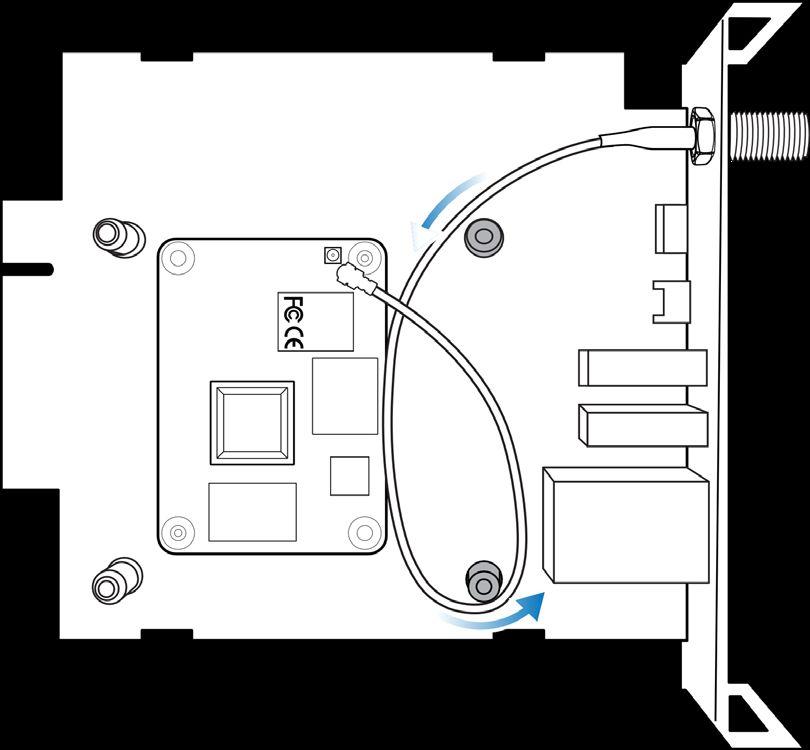
Introduction
This document describes the features, installation, connectivity, and configuration of the Raspberry Pi
Compute Module 4 support in NEC Large-Screen display models. Please see “Requirements” on page 10
for a current list of supported displays and Raspberry Pi hardware.

   Notes:

   1. The acts of disclosure, duplication, and modification of part or whole contents in this reference
      manual without permission are prohibited.
   2. The contents of this reference manual are subject to change without notice.
   3. Great care has been taken in the preparation of this reference manual; however, should you
      notice any questionable points, errors or omissions, please contact us.

   Copyright and Trademarks

   Copyright © 2021 Sharp NEC Display Solutions, Ltd.

   The content of this manual is furnished for informational use only, is subject to change without notice,
   and should not be construed as a commitment by Sharp NEC Display Solutions, Ltd. Sharp NEC
   Display Solutions, Ltd. assumes no responsibility or liability for any errors or inaccuracies that may
   appear in this manual.

   Windows® is a registered trademark of Microsoft Corporation.

   NEC is a registered trademark of NEC Corporation.

   Linux® is the registered trademark of Linus Torvalds in the U.S. and other countries.

   Raspberry Pi is a trademark of the Raspberry Pi Foundation.

   Apple, Macintosh, Mac, macOS and the Mac logo are trademarks of Apple Inc., registered in the U.S.
   and other countries.

   Ubuntu is a registered trademark of Canonical Ltd.

©2021 Sharp NEC Display Solutions, Ltd.                                                        Page 2 of 86
Contents
Introduction ................................................................................................................................. 2
Contents ...................................................................................................................................... 3
Revision History .......................................................................................................................... 7
Basic Features ............................................................................................................................ 8
GPIO Summary.......................................................................................................................... 10
Interface Board internal connections and jumpers ............................................................... 10
Requirements ............................................................................................................................ 10
Important Cautions ................................................................................................................... 11
About Wireless Connectivity (Wi-Fi and Bluetooth) .............................................................. 11
Operating System Programming Procedure .......................................................................... 12
1    Basic Setup and Configuration Steps ............................................................................... 13
2    Installing the Compute Module and NEC Compute Module Interface Board to the
     Display ................................................................................................................................. 14
3    Connections and Internal Operation ................................................................................. 20
    3.1      USB device connections to the Compute Module ...................................................................... 20
    3.2      USB connections for programming the Compute Module ......................................................... 20
    3.3      LAN connections ......................................................................................................................... 22
    3.4      Software control via IR Remote .................................................................................................. 24
    3.5      GPIO ............................................................................................................................................ 27
4    Preparing and running the tools to program the Compute Module ............................... 28
    4.1      Using a Windows PC as a host .................................................................................................... 28
5    Miscellaneous Configuration Items................................................................................... 33
    5.1      Enabling the onboard USB 2.0 controller ................................................................................... 33
    5.2      Enabling 4K@60Hz video output ................................................................................................ 33
    5.3      Configuring the correct HDMI video level encoding and decoding ............................................ 33
    5.4      To disable overscan (if black bars are visible on the sides of the screen) .................................. 35
    5.5      To rotate the screen image to portrait orientation .................................................................... 35
    5.6      To enable support for the IR Remote receiver using “lirc” ......................................................... 36
    5.7      To test support for the IR Receiver by outputting raw data ....................................................... 37
    5.8      To enable the serial port (UART) to the display and allowing application access ...................... 37
    5.9      Testing internal serial communications to the display using the Python based NEC PD SDK .... 38

©2021 Sharp NEC Display Solutions, Ltd.                                                                                                      Page 3 of 86
5.10 Configuring the Compute Module to shutdown using shutdown signal from the display ......... 38
5.11 Reading and setting the display’s internal Real Time Clock (RTC) from the OS ......................... 39
5.12 Using the display’s Watchdog Timer (WDT) ............................................................................... 40
5.13 Controlling the Compute Module power .................................................................................... 41
5.14 Controlling the cooling fan automatically based on the CPU temperature................................ 41
5.15 Checking and updating the display firmware version................................................................. 42
5.15.1 Update using the NEC Display Firmware Update Tool for Windows .................................. 42
5.15.2 Update display firmware using a USB storage device ........................................................ 43
6 Related OSD Settings ......................................................................................................... 44
6.1 Slot Compute Module Power Control Power Supply ................................................... 44
6.2 Slot Compute Module Power Control Power Button ................................................... 44
6.3 Slot Compute Module Power Control Reset ................................................................ 45
6.4 Slot Compute Module Power Setting Auto Power Up ................................................. 45
6.5 Slot Compute Module Power Setting Auto Shutdown ................................................. 45
6.6 Slot Compute Module Power Setting Power Supply Off Delay .................................... 46
6.7 Slot Compute Module Power Setting Auto Display Off ................................................ 46
6.8 Slot Compute Module Power Setting Off Warning ...................................................... 47
6.9 Slot Compute Module Advanced Setting Shutdown Signal.......................................... 47
6.10 Slot Compute Module Advanced Setting IR Signal ....................................................... 48
6.11 Slot Compute Module Advanced Setting Monitor Control .......................................... 48
6.12 Slot Compute Module Advanced Setting WDT............................................................. 48
6.13 Slot Compute Module Advanced Setting WDT Start Up Time ................................. 49
6.14 Slot Compute Module Advanced Setting WDT Period Time ................................... 49
6.15 Slot Slot Power ....................................................................................................................... 50
6.16 Input Advanced CEC CEC ............................................................................................... 50
6.17 Input Advanced CEC Search Device ............................................................................... 51
6.18 Control USB PC Source ...................................................................................................... 51
7 Useful Information and Commands .................................................................................. 54
7.1 To find out the IP address of the Compute Module from a terminal window ........................... 54
7.2 To restart from a terminal window............................................................................................. 54
7.3 To shutdown from a terminal window ....................................................................................... 54
7.4 To run the Raspberry Pi Config utility from a terminal window ................................................. 54
©2021 Sharp NEC Display Solutions, Ltd. Page 4 of 867.5 To change the keyboard layout to US from a terminal window ................................................. 54
7.6 To add and remove packages from Raspberry Pi OS .................................................................. 55
7.7 To update the Raspberry Pi......................................................................................................... 55
7.8 To install the Python serial module ............................................................................................ 55
7.9 To mount a USB flash drive from the terminal ........................................................................... 55
7.10 To access an SMB (Windows share) drive from the Raspberry Pi OS desktop ........................... 56
7.11 To list connected USB devices .................................................................................................... 56
7.12 To show available disk space ...................................................................................................... 56
7.13 To show internal information about the Raspberry Pi ............................................................... 56
7.14 To download a file to the current directory................................................................................ 56
7.15 To find a file by name.................................................................................................................. 57
7.16 To edit a protected system configuration file from the Raspberry Pi OS desktop ..................... 57
7.17 To prevent the screen saver from blanking the screen after several minutes ........................... 57
7.18 Monitoring the system processes, CPU usage, and memory ..................................................... 57
7.19 To enable and disable video output from the Compute Module to the display ........................ 57
7.20 To create an image of the Compute Module to backup or clone ............................................... 58
7.21 Debug GPIO lines and overlay assignments ................................................................................ 58
7.22 Assign different MAC address to the network interfaces ........................................................... 58
8 Troubleshooting .................................................................................................................. 59
9 Video CODECs .................................................................................................................... 64
10 Python Based NEC PD SDK ............................................................................................... 65
11 Compute Module Configuration Tool for Raspberry Pi OS ............................................. 67
12 Wireless connectivity installation and configuration ...................................................... 69
12.1 Important cautions ..................................................................................................................... 69
12.2 Parts identification ...................................................................................................................... 70
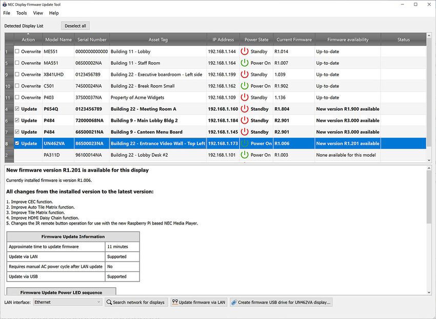
12.3 Installing the antenna connector to the Compute Module and routing the coax cable ............ 71
12.4 Enabling and disabling Wi-Fi at the hardware level.................................................................... 76
12.5 Selecting the external antenna in software ................................................................................ 76
12.6 Bluetooth functionality ............................................................................................................... 76
12.7 Troubleshooting wireless functionality....................................................................................... 76
13 External reference information .......................................................................................... 78
14 Frequently Asked Questions ............................................................................................. 80
©2021 Sharp NEC Display Solutions, Ltd. Page 5 of 8615 Known Issues ...................................................................................................................... 84 16 Support ................................................................................................................................ 85 17 Disclaimer ............................................................................................................................ 86 ©2021 Sharp NEC Display Solutions, Ltd. Page 6 of 86
Revision History
 Revision   Date                   Modified by         Description
 210526     May 26, 2021           Will Hollingworth   Initial release
 211020     October 20 2021        Will Hollingworth   Add wireless information

©2021 Sharp NEC Display Solutions, Ltd.                                           Page 7 of 86
Basic Features
    •   Operating System support
            o Select from many publicly available OS distributions and images depending on the
                application, such as: fully featured and ready to use networked media players, kiosk
                interfaces, full desktop based operating systems, and minimal systems.
                A custom developed NEC Media Player image is also available.
    •   Network connectivity
            o Gigabit LAN connection on the Raspberry Pi Compute Module Interface Board for direct
                high-speed connection to the Compute Module.
            o 10/100 LAN switch internal to the display provides network connectivity to both the
                display and Raspberry Pi Compute Module using a single network connection. The
                display’s LAN control interface and the Compute Module will have their own IP address
                and network settings.
            o (Multiple LAN port display models 1) Two of the display’s LAN switch ports are available
                externally for daisy-chaining other devices.
                     - LAN1 port should be used to connect to the network.
                     - LAN2 output can be used to connect other LAN devices or displays.
            o Built-in Wi-Fi on supported models.
    •   USB connectivity
            o Two USB 2.0 Type-A connectors (500mA power) on the Raspberry Pi Compute Module
                Interface Board for connecting devices such as keyboards, mice, and other USB
                peripherals.
            o (Display models with “USB-A” connection 2) An additional USB 2.0 internal connection to
                the display’s built-in USB Type-A port. This port can be switched between the Raspberry
                Pi Compute Module, another SDM based device, or an external PC. This can be set to
                switch automatically, depending on the currently selected video input, or fixed to a
                specific source.
            o Direct programming of the Compute Module from an external PC via a USB 2.0 Micro-B
                connector on the Raspberry Pi Compute Module Interface Board.
    •   Internal IR Remote receiver and pass through to the Raspberry Pi Compute Module
            o The display's IR Remote can be used to operate software running on the Raspberry Pi
                Compute Module, such as a media player, via standard IR Remote Control units. The IR
                Remote communicates to the Compute Module via the display's internal remote control
                sensor or external KT-RC3 sensor. It will be necessary to configure such software with
                the IR codes for the remote control units being used.
            o This uses GPIO 18 on the Raspberry Pi.

1
 Current display models with multiple LAN ports on the terminal panel: MA431, MA491, MA551, P435, P495, P555
2
 Current display models with port labeled “USB-A” on the terminal panel: MA431, MA491, MA551, P435, P495,
P555

©2021 Sharp NEC Display Solutions, Ltd.                                                        Page 8 of 86
• CEC support between the display and the Raspberry Pi Compute Module.
o Facilitates the use of the display’s IR Remote buttons to control the basic navigation
functions of compatible software, such as media players.
• Internal serial connection between the display and the Raspberry Pi Compute Module
o Allows full control and monitoring of the display from the Compute Module.
o This uses GPIO 14 & 15 (UART0) on the Raspberry Pi Compute Module.
o A Python based SDK is available from Sharp NEC Display Solutions for easy software
development. See Python Based NEC PD SDK on page 65.
• Real Time Clock support via the display’s internal clock
o The display’s internal Real Time Clock can be read and set via the Compute Module,
using the internal serial connection and the Python based SDK.
o This can be used to set the system time when no network connection is available.
• Shutdown signal support
o The display can signal to the Operating System, running on the Raspberry Pi Compute
Module, that the power is about to turn off so the software and OS can shutdown
gracefully.
o This uses GPIO 23 on the Raspberry Pi Compute Module.
• Full power control
o Power for the Compute Module can be configured to automatically turn on when the
display is turned on from a standby mode, or it can be turned on separately via the
display’s OSD, HTTP interface, or network commands.
o By default, the Compute Module will remain powered on even when the display goes
into standby mode and can be turned off separately via the display’s OSD, HTTP
interface, or network commands.
The display can be configured to turn off the Compute Module power with the display
power.
• Watchdog timer support
o Can be used to reset a locked CPU by automatically restarting the Compute Module. A
restart will occur if no periodic reset signal is received from the Compute Module within
a certain time period.
• Built in touchscreen support
o For display models integrated with an optional 3rd party touchscreen, the USB touch
device will appear as a standard USB HID (Human Interface Device) device to the
Compute Module.
• Wi-Fi and Bluetooth support
o See the following section About Wireless Connectivity (Wi-Fi and Bluetooth) on page 11
for information about the wireless connectivity.
• Cooling
o The large heatsink combined with cooling fans integrated within the display simplifies
heat management.
©2021 Sharp NEC Display Solutions, Ltd. Page 9 of 86o A temperature sensor within the display automatically starts the cooling fans when
needed. Additionally, the Compute Module itself can request the cooling fans run by
driving GPIO 24 to a high state. This is compatible with the Raspberry Pi OS Fan GPIO
control mechanism.
• Status indicator
o LED indicator on the Raspberry Pi Compute Module Interface Board shows the status of
power (red) and activity (orange).
GPIO Summary
• GPIO 14 & 15 (UART0 TX & RX) – internal serial connection to the display for control
• GPIO 18 – (input to Compute Module) demodulated IR receiver from the display
• GPIO 23 – (input to Compute Module) shutdown signal
• GPIO 24 – (output from the Compute Module) cooling fan control
See section 3.5 GPIO on page 27 for more details.
Interface Board internal connections and jumpers
• A jumper header labeled EEPEOM_nWP on the Interface Board can be used to write-protect the
Compute Module’s EEPROM by installing a jumper across the two pins.
• (DS1-IF21CE interface board only.) A jumper header labeled WF_nDisable on the Interface
Board can be used to disable the Compute Module’s Wi-Fi function by installing a jumper across
the two pins.
Requirements
• Compatible NEC display models
o M431 o MA431 o ME431 o P435
o M491 o MA491 o ME501 o P495
o M551 o MA551 o ME551 o P555
o M651 o ME651
• NEC Compute Module 4 Interface Board
o DS1-IF20CE or DS1-IF21CE
• Raspberry Pi Compute Module 4
o Supports all eMMC based variants, including all RAM and wireless configurations.
©2021 Sharp NEC Display Solutions, Ltd. Page 10 of 86o Note: “Lite” versions of the Compute Module 4 without onboard eMMC Flash memory
are not supported.
• Internet connection
• LAN hub and standard network cables
• Standard USB 2.0 or 3.x cable (USB to USB Micro-B) for programming.
Lengths of up to 10 feet or 2.5 M can be used with high quality USB cables.
• Host PC running either Windows, macOS, or Ubuntu, or a standard Raspberry Pi 1 / 2 / 3 / 4
running Raspberry Pi OS
• USB keyboard and mouse for connecting to the display (recommended)
• Operating system .img file
• Software configuration tools (see following sections)
Important Cautions
• Always disconnect the display from AC power when inserting or removing the Interface Board
from the display.
• The two sets of connectors on the Compute Module 4 and the Interface Board are very fragile
and are rated at about 30 insertions maximum. Therefore, do not mate and un-mate the two
unnecessarily.
• When mating the Compute Module 4 to the Interface Board pay careful attention to the
orientation of the Compute Module.
• The included heatsink should be attached to the Compute Module after testing and before final
installation to provide cooling for the Compute Module. The included thermal conductive sheet
should always be used between the heatsink and the Compute Module.
• Disconnect the programming USB Micro-B cable from the Interface Board when programing is
complete. Leaving it connected will result in the USB ports and internal 10/100 LAN being
inactive.
About Wireless Connectivity (Wi-Fi and Bluetooth)
• The DS1-IF21CE interface board together with a wireless enabled version of the Compute
Module 4 and external antenna kit can be used for Wi-Fi functionality. At the time of writing,
Bluetooth functionality is disabled pending regulatory approvals. See the relevant sections of
this guide for information on installing and configuring the wireless functions.
• An external USB wireless adapter “dongle” can be used can be used with either the DS1-IF20CE
or DS1-IF21CE Interface Boards to provide wireless functions.
©2021 Sharp NEC Display Solutions, Ltd. Page 11 of 86Operating System Programming Procedure If a Compute Module was included with the kit, it may be pre-programmed with the NEC MediaPlayer image. This can be overwritten as desired. Standard Compute Modules from Raspberry Pi are not programmed with an Operating System by default. The OS can be installed after placing the Compute Module in programming boot mode. This allows the Compute Module to appear as a USB device to another “host” PC or Raspberry Pi. The Operating System is then programmed, or “installed”, from the host to the Compute Module over USB. After the OS is programmed successfully, any necessary configuration options can be made, and the Compute Module can be restarted in normal boot mode. The “host” can be a PC running Windows® or Linux®, or a standard Raspberry Pi 1, 2, 3, or 4 with Raspberry Pi OS. If using a Linux based PC or Raspberry Pi as a host, a small utility will need to be downloaded and compiled on the host. Important: The Compute Module will typically not display video until it has been programmed with a compatible Operating System. ©2021 Sharp NEC Display Solutions, Ltd. Page 12 of 86
1       Basic Setup and Configuration Steps
 The following list shows the basic steps that will be performed:

    1. Physically install the Raspberry Pi Compute Module 4 into the NEC Compute Module Interface
       Board and install into the display. See section 2 on page 14 for details.
    2. Connect the host PC to the Interface Board in the display via the USB Micro-B connector for
       programming the module. Connect other USB devices, such as a keyboard and mouse, for
       configuration and use. See section 3 on page 20 for details.

 Note: If the Compute Module is to be programmed with a new OS, follow these steps after
 connecting any USB devices:

    1. Select and download the OS to install on the Compute Module as well as any other software
       tools. See section 4 on page 28 for details.
    2. Prepare and run the tools to make the Compute Module appear as a Mass Storage device on the
       host system so the OS can be imaged.
    3. Image the OS from the host system to the Compute Module.
    4. Configure any boot options by editing the config.txt and cmdline.txt files on the boot partition.
       See section 5 on page 33 for details.
    5. Restart the Compute Module.
    6. Configure other boot and runtime options. See section 7 on page 54 for details.
    7. Check for any system and firmware updates. See section 7.7 on page 55.

©2021 Sharp NEC Display Solutions, Ltd.                                                   Page 13 of 86
2 Installing the Compute Module and NEC Compute
Module Interface Board to the Display
1. Disconnect AC power from the display.
2. Install a Compute Module into the connector of the Interface Board. Check that the Compute
Module is oriented correctly before fully inserting it into the connector. Carefully align the two
rows of connectors and press together evenly to snap together.
Caution: Take static precaution measures when handling the boards.
Figure 2-1: Install the Raspberry Pi Compute Module
3. Confirm the Compute Module is correctly mated by looking at each corner of the Interface
Board. Metal posts should protrude from two corners, diagonal from each other.
Figure 2-2: Confirm correct installation by alignment of metal posts
Note: to ensure proper orientation for Compute Module installation, the Interface Board has
two diagonal posts that protrude through two corners of the Compute Module. The opposite
two corners of the Compute Module rest on two screw hole pillars. It is not necessary to secure
©2021 Sharp NEC Display Solutions, Ltd. Page 14 of 86the Compute Module using screws since the heatsink will be used to hold it in place. However, if
desired two 2mm or 2.5mm M2 screws [not supplied] can be used.
4. Check the distance between the Interface Board and Compute Module; it should be equal on all
sides.
Figure 2-3: Check all sides of the Compute Module on the Interface Board
5. (DS1-IF21CE interface board only.) If installing the antenna for wireless functionality, follow the
steps in Section 12 on page 69, then return to the following steps.
6. Peel the liner from one side of the thermal conductive sheet and stick the sheet to the
underside of the heatsink.
Important: Carefully align the thermal conductive sheet within the engraved marks before
adhering the sheet to the heatsink for proper alignment over the Raspberry Pi.
Figure 2-4: Place thermal conductive sheet
7. Peel the remaining liner from the thermal conductive sheet when you are ready to attach the
heatsink to the Compute Module Interface Board.
Important: Remove the liner before attaching the heatsink to the Interface Board.
©2021 Sharp NEC Display Solutions, Ltd. Page 15 of 868. Attach the heatsink using the four M3 screws supplied with the kit.
Important: Orientate the heatsink with the slotted hole in the bottom left corner before
attaching, as shown in the figure. The thermal conductive sheet will press against the top of the
Compute Module.
Figure 2-5: Attach the heatsink to the Interface Board
©2021 Sharp NEC Display Solutions, Ltd. Page 16 of 86Confirm the heatsink is seated correctly by looking at the screw-hole posts on the Interface
Board. The two posts on the outside edge should be inserted and flush to the surface of the
heatsink. The heatsink rests on top of the two posts closest to the USB and LAN ports
connection.
Check the distance between the Interface Board and the heatsink; it should be equal on all sides,
the thermal sheet should press against the Compute Module, and the two screw-hole posts on
the outside edge should be inserted into the heatsink.
Figure 2-6: Check all sides of the heatsink
©2021 Sharp NEC Display Solutions, Ltd. Page 17 of 869. On the side of the display, remove the two screws holding the slot cover in place and then
remove the slot cover.
Note:
• Set the screws aside; they are used in the next step for securing the Compute Module
Interface Board in the display.
• Do not discard the slot cover. It helps to limit dust and debris from entering the display
and protect the internal components. Store it in a safe place for future use in case the
Compute Module Interface Board is removed from the display later.
Figure 2-7: Remove slot cover from the display
©2021 Sharp NEC Display Solutions, Ltd. Page 18 of 8610. Insert the Interface Board into the slot. Make sure to carefully align and fully insert the Interface
Board into the slot and then secure it with the two screws removed in the previous step.
Figure 2-8: Insert the Interface Board in the display
11. Reconnect AC power to the display.
©2021 Sharp NEC Display Solutions, Ltd. Page 19 of 863 Connections and Internal Operation 3.1 USB device connections to the Compute Module The two USB Type-A inputs on the side of the Interface Board are for connecting downstream USB devices, such as a keyboard and mouse, additional storage, external sensors and devices, or a Wi-Fi adapter, to the Compute Module. Both connectors are USB 2.0 and can supply 500mA of current each. On some display models 1 there is an additional USB input on the display itself labeled “USB-A” that can be switched between the Compute Module, Internal PC (SDM), and an external PC connected to the USB-B connection on the display. It can be configured via the display’s OSD “PC SOURCE” setting (see section 6.18 on page 51) to switch automatically depending on the currently selected video input or fixed to a specific source. This allows devices such as a mouse or other input device to be shared automatically between different sources. For display models1 that have been integrated with an optional 3rd party touchscreen, the internal USB connection from the touch sensor will also follow the “PC SOURCE” setting so that as video inputs on the display are changed, the touchscreen connection will automatically switch to the correct source device. Figure 3.1-1: USB Device Connection 3.2 USB connections for programming the Compute Module To program the Compute Module, an external “host” PC is connected to the USB Micro-B connector on the Interface Board. The Boot Mode switch on the side of the Interface Board should be moved to the position towards the USB connectors and the display powered on. After running the “rpiboot” utility, the Compute Module 4 will then appear as a USB device to the “host” PC, allowing it to be programmed. 1 Current display models with a “USB-A” port on the terminal panel and PC SOURCE in the OSD menu: MA431, MA491, MA551, P435, P495, P555 ©2021 Sharp NEC Display Solutions, Ltd. Page 20 of 86
Note: The postion of the Boot Mode switch is only recognized when power is initially applied to the
 Compute Module. Changing the position of the switch after power is applied to the Compute Module
 does not affect its operating/boot mode.

Figure 3.2-1: BOOT MODE switch - programming mode

   Important: Remove the cable connected to the USB Micro-B port and the host PC after programming
   is complete. Failure to disconnect the cable may result in connected USB peripherals and the internal
   LAN hub not being detected by the Compute Module.

Figure 3.2-2: Host USB Connection for Programming

©2021 Sharp NEC Display Solutions, Ltd.                                                    Page 21 of 86
3.3 LAN connections
The Compute Module Interface Board features an onboard Gigabit LAN connection for direct high-speed
connection to the Compute Module.

Additionally, an internal 10/100 Mbps interface on the Interface Board and LAN switch within the display
provides network connectivity to both the display and Raspberry Pi Compute Module using a single
network connection.

      •    The display’s LAN control interface and the Compute Module will have their own IP address and
           network settings and can be configured via the display’s OSD and internal web page.
      •    The IP address and network settings of the Compute Module are configured within the OS
           running on it.
      •    (Multiple LAN port models only 1) Two of the display’s LAN switch ports are available externally
           for daisy-chaining other devices.
               o LAN1 port should be used to connect to the network.
               o LAN2 output can be used to daisy-chain connect other LAN devices or displays.

    Note: The internal 10/100 Mbps interface uses LAN controller (LAN9514) connected to the Compute
    Module via USB 2.0. It is necessary to enable USB host mode support on the OS to use this interface.
    See 5.1 Enabling the onboard USB 2.0 controller on page 33 for more information.

      Important: Both the Gigabit and 10/100 Mbps LAN interfaces will be assigned a MAC address based
      on the serial number of the Compute Module. At the time of writing, Raspberry Pi OS will assign
      identical MAC and IP addresses to both interfaces. This will lead to an illegal ethernet condition if both
      network ports are connected to the same network and may result in degraded or no network
      connectivity.

      It is possible to assign a different MAC address to one of the network interfaces to avoid this. See
      section 7.22 on page 58.

    Note: The LAN2 connection should be used for connecting to other displays that are daisy-chained or to
    other LAN devices. Functions such as AUTO ID and AUTO IP will not work correctly if displays are not
    daisy-chained correctly using the LAN1 and LAN2 connections.

1
    Current models with multiple LAN ports on the terminal panel: MA431, MA491, MA551, P435, P495, P555

©2021 Sharp NEC Display Solutions, Ltd.                                                           Page 22 of 86
Figure 3.3-1: LAN Connections Models: MA431 / MA491 / MA551 / P435 / P495 / P555 Figure 3.3-2: LAN Connections Models: M431 / M491 / M551 / M651 / ME431 / ME501 / ME551 / ME651 ©2021 Sharp NEC Display Solutions, Ltd. Page 23 of 86
3.4 Software control via IR Remote
An IR Remote can be used to control software running on the Compute Module, such as a media player.
IR Remote signals are received via the display’s built-in remote control sensor or via an optional external
KT-RC3 sensor.

 Note: The display’s built-in sensor will automatically be disabled when the external KT-RC3 sensor is
 connected.

This feature can be used in two ways:

    •   As a CEC (Consumer Electronics Control) device
        Specific buttons on the NEC IR Remote will perform actions, such as Stop, Play, Next, Previous,
        etc., on CEC enabled software on the Compute Module. The display is responsible for receiving
        and decoding the IR Remote signals, and then forwarding them on to the Compute Module as
        standard CEC commands.

        Only the NEC IR Remote can be used, and CEC support must be enabled on the display and in
        the Operating System on the Compute Module. See Figure 5.15.1-3: Supported CEC buttons on
        the NEC IR Remote in CEC MODE 1 on page Error! Bookmark not defined. and Figure 5.15.1-4:
        Supported CEC buttons on the NEC IR Remote in CEC MODE 2 on page Error! Bookmark not
        defined..

        The buttons used for CEC commands are dual-function on the NEC IR Remote. When the
        display’s OSD is active (being displayed) the buttons will perform display related functions.
        When the OSD is not active the buttons will perform CEC functions. Press the EXIT button on the
        IR Remote to exit and deactivate the OSD.

        See section 6.16 on page 50 and section 6.17 on page 51 for more information.

    •   As a generic IR receiver
        Demodulated raw IR signals received by the remote control sensor are passed to the Raspberry
        Pi Compute Module via GPIO 18. Packages such as lirc can be used to decode the raw IR signals.

        IR Remotes other than the NEC IR Remote, such as a standard MCE/RC6 type, can be used if
        they use a 40 KHz carrier. See section 5.6 on page 36, section 5.7 on page 37, and section 6.5 on
        page 45 for more information.

©2021 Sharp NEC Display Solutions, Ltd.                                                       Page 24 of 86
Figure 3.4-1: Using the NEC IR Remote with CEC Figure 3.4-2: Using other IR Remotes with raw IR signals ©2021 Sharp NEC Display Solutions, Ltd. Page 25 of 86
Figure 3.4-3: Supported CEC buttons on the NEC IR Remote in CEC MODE 1 Figure 3.4-4: Supported CEC buttons on the NEC IR Remote in CEC MODE 2 The mapping of buttons on the NEC IR Remote to CEC commands has two different modes that can be selected via the OSD menu. Please see section 6.16 Input Advanced CEC CEC on page 50. ©2021 Sharp NEC Display Solutions, Ltd. Page 26 of 86
Note: The Volume Up, Down and Mute buttons will control audio on the display rather than on any
media player software running on the Compute Module. These buttons will only operate in CEC mode
if a CEC compatible audio amp/receiver is used.
3.5 GPIO
The following GPIO are used for signaling between the display and Compute Module:
• GPIO 14 & 15 (UART0 TX & RX) – internal serial connection to the display for control. This can be
enabled and disabled via the OSD setting (see 6.11 Slot Compute Module Advanced
Setting Monitor Control on page 48.)
• GPIO 18 – (input to Compute Module) demodulated IR receiver from the display. This can be
enabled and disabled via the OSD setting (see 6.10 Slot Compute Module Advanced
Setting IR Signal on page 48.)
• GPIO 23 – (input to Compute Module) shutdown signal (goes low to signal the display is about to
shut down power to the Compute Module). This can be enabled and disabled via the OSD
setting (see 6.9 Slot Compute Module Advanced Setting Shutdown Signal on page 47.)
• GPIO 24 – (output from the Compute Module) cooling fan control (set high to force the display’s
cooling fans on).
Figure 3.5-1: GPIO
©2021 Sharp NEC Display Solutions, Ltd. Page 27 of 864 Preparing and running the tools to program the
Compute Module
The following steps explain how to use a Windows PC as a host system to program the Compute Module.
These steps will make the Compute Module appear as a mass storage device to the host PC so it can be
programmed with an OS image. Similar steps can be used for macOS and Linux based systems also –
please consult the Raspberry Pi documentation and website for the appropriate tools and steps.
4.1 Using a Windows PC as a host
1. Download and install either the official Raspberry Pi Imager application (recommended),
balenaEtcher or Win32DiskImager tool from the following locations. This will be used to write the
OS .img file to the Compute Module.
https://www.raspberrypi.org/software/
https://etcher.io/
https://sourceforge.net/projects/win32diskimager/
2. Download and install the Compute Module boot installer. This will install Windows drivers for
accessing the Compute Module as a mass storage device.
https://github.com/raspberrypi/usbboot/blob/master/win32/rpiboot_setup.exe
3. Download the OS image to be programmed to the Compute Module. The download may need to be
unzipped to reveal the .img file. Refer to the following section and the Raspberry Pi website for a list
of supported OSs:
https://www.raspberrypi.org/downloads/
4. A text editor that is compatible with UNIX type line endings, such as Notepad++, is highly
recommended for making boot configuration file changes from Windows. Notepad++ is available
from:
https://notepad-plus-plus.org/
5. Set the Compute Module to boot mode for programming.
To set programming boot mode:
a. Turn off the display’s AC power switch.
b. Connect a USB cable from the USB Micro-B connector on the Interface Board to the host PC.
c. Move the BOOT MODE switch on the Compute Module Interface Board terminal panel to
the programming boot mode position.
©2021 Sharp NEC Display Solutions, Ltd. Page 28 of 86Figure 4.1-1: BOOT MODE switch - programming mode
d. Turn on the display’s AC power switch. Verify that the Compute Module is powered on.
Navigate the OSD to SLOT COMPUTE MODULE POWER CONTROL POWER SUPPLY
and make sure ON is selected (displayed in yellow).
e. Verify that the Compute Module is powered on by looking at the LED indicator next to the
BOOT MODE switch. The LED should be red when power has been applied to the Interface
Board.
See the Troubleshooting section for “RPi Boot” is unable to detect the Compute Module on
page 59 if the LED indicator does not illuminate.
6. Run the RPiboot application installed by the Compute Module boot installer by selecting “rpiboot”
from the Windows Start menu. A command window like the one shown below should appear and
close within a few seconds.
©2021 Sharp NEC Display Solutions, Ltd. Page 29 of 86The indicator LED next to the BOOT MODE switch will turn from red to orange color.
At this point Windows may show a message that a new unformatted drive has been connected –
do not open or format the drive.
If the window stays open and displays only “Waiting for BCM2835/6/7/2711…” then the
Compute Module has not been detected. See the Troubleshooting section for “RPi Boot” is
unable to detect the Compute Module on page 59.
7. Use the Raspberry Pi Imager, balenaEtcher, or Win32DiskImager tool to write the OS image file
a. Run the tool.
b. Select the downloaded OS .img file as the source image to write to the Compute Module.
c. Select the Compute Module “drive” as the target.
d. Click “Flash” or “Write” to begin writing and verifying the image. This process should take
approximately 5 to 15 minutes depending on the size of the OS image file.
e. When finished, the drive should contain the boot files for the OS.
Note: The imaging tool may “eject” the Compute Module’s drives when writing and verification is
complete. If so, disconnect and reconned the USB cable to the PC and the drives should reappear.
8. Configuring boot options:
©2021 Sharp NEC Display Solutions, Ltd. Page 30 of 86Some settings in the boot files config.txt and cmdline.txt can be modified at this stage.
For example, settings to correctly enable the USB 2.0 controller on the Compute Module, set the
video output level, and to enable the IR Remote module (lirc) can be made while still in
Windows.
Navigate to the drive letter of the Compute Module to see the boot files.
Use a text editor that is compatible with UNIX type line endings such as Notepad++
(https://notepad-plus-plus.org/)
See section 5 on page 33 of this document for further information on specific configurations.
9. The Compute Module in the display can now be restarted in normal mode to boot the device.
a. Turn off the display’s AC power switch.
b. Disconnect the USB cable from the USB Micro-B connector on the Interface Board.
c. Move the BOOT MODE switch on the Compute Module Interface Board terminal panel to
the normal operating mode position.
Figure 4.1-2: BOOT MODE switch - normal mode
d. Turn on the display’s AC power switch.
e. Verify that the Compute Module is powered on. Navigate the OSD to SLOT COMPUTE
MODULE POWER CONTROL POWER SUPPLY and make sure ON is selected (displayed
in yellow).
f. Make sure the Compute Module input on the display is selected.
©2021 Sharp NEC Display Solutions, Ltd. Page 31 of 86The boot-up sequence for the OS programmed to the Compute Module should be seen on the screen
within a few seconds.
See the troubleshooting section on page 59 if no boot screen is seen.
10. Check for any system and firmware updates to the OS (Internet connection to the display or
Compute Module required). See section 7.7 on page 55.
©2021 Sharp NEC Display Solutions, Ltd. Page 32 of 865 Miscellaneous Configuration Items
Note: Many of the options for the Raspberry Pi OS can be automatically configured using the
Compute Module Configuration Tool for Raspberry Pi OS see “Compute Module Configuration Tool for
Raspberry Pi ” on page 67.
5.1 Enabling the onboard USB 2.0 controller
The default settings on Raspberry Pi OS do not enable the USB 2.0 controller in host mode. This
prevents any USB peripherals, including the onboard USB LAN controller (LAN9514), from operating.
To enable the enable the USB 2.0 controller in host mode add the following line to the config.txt file:
dtoverlay=dwc2,dr_mode=host
5.2 Enabling 4K@60Hz video output
The default settings on Raspberry Pi OS do not enable the 4K@60Hz video signal format, and the output
format may be limited to 4K@30Hz.
To enable the 4K@60Hz format add the following line to the config.txt file:
hdmi_enable_4kp60=1
Note: For the best screen image use the display’s native 4K resolution of 3840x2160.
5.3 Configuring the correct HDMI video level encoding and decoding
The Compute Module can output video to displays that have video levels either in the range 0-255
(known as “full”) or in the range 16-235 (known as “limited” or “RGB limited”). Configuration settings for
the OS determine which range will be output. The NEC display can accept either range sets and will
display the video correctly, as long as it is correctly configured to match the video range from the
Compute Module. However, it is recommended to use the “full” range since it will give the maximum
number of displayable colors.
A mismatch between the output range from the Compute Module and the display will result in either:
• Blacks appearing as gray and whites being too dark.
o Cause: Compute Module outputs “limited” video range and the display is set to “FULL”.
Or
• Dark gray levels being crushed and whites being clipped.
o Cause: Compute Module outputs “full” video range and the display is set to “LIMITED”.
The video range used by the display is configured as follows:
1. Navigate to the INPUT menu on the OSD.
©2021 Sharp NEC Display Solutions, Ltd. Page 33 of 861
2
3
2. Select INPUT SIGNAL INFORMATION.
3. The VIDEO RANGE setting determines how the display will handle the video from the Compute
Module.
• FULL - Use FULL if the Compute Module is configured to output “full” video in the range 0-
255. This is the recommended configuration since it provides the maximum number of
displayable colors. The display will not modify the range of the video signal levels.
• LIMITED - Use LIMITED if the Compute Module is configured to output “limited” video in the
range 16-235. The display will expand the video from the range 16-235 to 0-255 internally.
The video range used by the Compute Module depends on the Operating System. By default and
depending on the OS, many distributions will automatically output a video signal to the display that uses
video levels 16 to 235. A configuration file or menu setting is used to configure the video level.
For Raspberry Pi OS and many other OS distros, the current video settings can be confirmed by typing
the following into a terminal window:
tvservice –s
The output should show something similar to the following:
“HDMI CEA (16) RGB lim 16:9, 1920x1080 @ 60.00 Hz, progressive”
If “lim” is shown, it means that limited 16 – 235 video is being output to the display.
To change this setting, a configuration file must be edited. If changing the setting from the Compute
Module itself, use the built in text editor “Nano” to edit the config.txt file:
sudo nano /boot/config.txt
Scroll to the end of the file and enter the following line:
hdmi_pixel_encoding=2
Save the file by pressing CONTROL + o then ENTER
Exit Nano by pressing CONTROL + x
Restart the Compute Module by typing:
sudo reboot
©2021 Sharp NEC Display Solutions, Ltd. Page 34 of 86When rebooted, confirm the video levels are correct by using the following command again:
tvservice –s
The output should now show “full”
“HDMI CEA (16) RGB full 16:9, 1920x1080 @ 60.00 Hz, progressive”
5.4 To disable overscan (if black bars are visible on the sides of the
screen)
Either
• Run the Raspberry Pi Config utility from the terminal
sudo raspi-config
Select: 9 Advanced Options
Select: A1 Overscan
Select: No
Or
• Edit the config.txt file to disable overscan:
sudo nano /boot/config.txt
Look for the following section:
# uncomment this if your display has a black border of unused pixels
visible
# and your display can output without overscan
#disable_overscan=1
Edit the last line to remove the #.
disable_overscan=1
Save the file and reboot.
5.5 To rotate the screen image to portrait orientation
Use the Screen Configuration tool available on the OS Preferences menu. Select the screen and select
Orientation. Change the setting to “Left”. This will match the display being physically rotated
counterclockwise into portrait orientation.
Important: Using the display rotated clockwise is not approved due to the cooling design.
©2021 Sharp NEC Display Solutions, Ltd. Page 35 of 86Note: The orientation of the display’s OSD can be changed to match by changing the SYSTEM OSD
OSD ROTATION setting.
5.6 To enable support for the IR Remote receiver using “lirc”
1. Make sure the display support is enabled.
a. On the NEC display select the SLOT menu on the OSD.
b. Select the ADVANCED SETTINGS option after COMPUTE MODULE.
c. Confirm that the IR SIGNAL is set to ENABLE.
a
b
c
2. Edit the config.txt file to enable support for lirc:
sudo nano /boot/config.txt
a. Look for the following section:
#uncomment this to enable the lirc-rpi module
#dtoverlay=lirc-rpi
b. If present, edit the last line to remove the # otherwise add the following line to the end
of the list:
dtoverlay=lirc-rpi
c. Save the file by pressing CONTROL + o then ENTER.
d. Exit Nano by pressing CONTROL + x.
Notes:
• A reboot is usually necessary to enable support.
• If lirc support is not included with the OS, it can be installed using the following:
sudo apt install lirc
©2021 Sharp NEC Display Solutions, Ltd. Page 36 of 86• Additional configuration may be required in the OS and application being used.
5.7 To test support for the IR Receiver by outputting raw data
Make sure lirc is installed using:
sudo apt install lirc
Output raw data from the IR receiver as follows:
sudo /etc/init.d/lirc stop
mode2 -d /dev/lirc0
Point an IR Remote at the IR sensor on the display and press some buttons. Output should be seen
showing the raw pulses received.
5.8 To enable the serial port (UART) to the display and allowing
application access
To enable the UART communications with the display so that applications on the Compute Module can
communicate with the display:
1. On the NEC display navigate to the SLOT menu on the OSD.
2. Select the ADVANCED SETTINGS options after COMPUTE MODULE.
3. Confirm that the MONITOR CONTROL is set to ENABLE.
1
2
3
4. Edit the config.txt file to allow application access to the serial port, by editing to either add or
change so there is a line with:
enable_uart=1
©2021 Sharp NEC Display Solutions, Ltd. Page 37 of 865. Edit the cmdline.txt file to allow app access to the serial port and prevent bootup information
being sent to the display by removing any section with:
console=serial0,115200
Important: When the Raspberry Pi boots up, all the bootup information can be sent to the serial port
for debugging purposes. Since this serial port is connected internally to the display, this may
overwhelm the display and cause erratic behavior (such as the OSD flashing, random operations
being performed, slow bootup of the Compute Module, etc.). If the internal connection is enabled (the
MONITOR CONTROL setting on the COMPUTE MODULE ADVANCED SETTINGS menu of the
OSD is set to ENABLE) then the bootup information must be disabled.
5.9 Testing internal serial communications to the display using the
Python based NEC PD SDK
1. Install the Python based NEC PD SDK files, and download the examples. See Python Based NEC
PD SDK on page 65.
2. If necessary, install the Python serial module. This should normally be automatically installed.
sudo apt install python-serial
3. Run the test file in the SDK.
python test_routines_example.py
4. The application should output information about the display, such as model name and serial
number.
Note: Confirm the MONITOR CONTROL is set to ENABLE on the OSD.
5.10 Configuring the Compute Module to shutdown using shutdown
signal from the display
To enable the Shutdown Signal from the display:
1. On the NEC display navigate to the SLOT menu on the OSD.
2. Select the ADVANCED SETTINGS options after COMPUTE MODULE.
3. Confirm that the SHUTDOWN SIGNAL is set to ENABLE.
©2021 Sharp NEC Display Solutions, Ltd. Page 38 of 861
2
3
Raspberry Pi OS includes an overlay for directly monitoring a GPIO used for signaling system shutdown.
The configuration settings can be made directly to the “config.txt” file by adding a line such as the
following example:
dtoverlay=gpio-shutdown,gpio_pin=23
See the following information for configuring the various boot overlay options:
https://github.com/raspberrypi/firmware/blob/master/boot/overlays/README
Alternatively, an example Python script rpi_shutdown.py is included with the Python based NEC PD
SDK. The script shows how to monitor GPIO 23 for a high to low transition, and how to use this to
gracefully shutdown the Operating System on the Compute Module before power to the module is
removed by the display. Normally this script should be started when the Operating System starts. This
can be accomplished by adding it to the /etc/rc.local file on the system. See the instructions
provided in the sample file for more details.
5.11 Reading and setting the display’s internal Real Time Clock (RTC)
from the OS
The Compute Module does not include a Real Time Clock, so the correct time must be configured at each
startup. This is usually done via a network connection to an NTP time server; however, the Compute
Module can read the display’s internal Real Time Clock as well.
The display’s internal Real Time Clock can be read and set from the Compute Module via the internal
serial connection (UART). This can be useful in situations where the Compute Module is unable to get the
current time from the network.
The Python based NEC PD SDK includes the following sample files:
©2021 Sharp NEC Display Solutions, Ltd. Page 39 of 86• set_system_to_display_clock.py - Reads the display’s internal clock via the internal
serial connection and sets the system time accordingly. This file can be added to a startup script
on the system, if necessary, to set the OS time from the display if no network connection is
available.
• set_display_to_system_clock.py - Sets the display’s internal clock based on the current
system time on the Compute Module.
See the files included in the SDK for more details. See Python Based NEC PD SDK on page 65.
5.12 Using the display’s Watchdog Timer (WDT)
The display features an internal Watchdog Timer that can be used to automatically restart the Compute
Module if it stops responding; for example, if it hangs for some reason.
To use this feature, a background application is configured to periodically send reset commands to the
display via the internal UART. The display will expect to receive these reset commands as an indication
that the Compute Module is functioning normally. If, for some reason, the reset commands are not
received as expected the display will send a reset signal to the Compute Module.
Use of the Watchdog Timer is optional and requires configuring the Operating System to start the
background application at bootup. The Watchdog Timer is enabled and configured via the OSD or
communications commands. The background application must send the reset command at least as often
as the Period Time configured via the OSD. If three consecutive reset commands are not received, the
display will send a reset signal to the Compute Module.
There are two time periods that can be configured for the Watchdog Timer:
• Start Up Time – This sets the time delay for when the display should start receiving WDT reset
commands, via the internal UART, after power is applied to the Compute Module.
This timer’s value should be set high enough to include time for the operating system to fully
load on the Compute Module, and for the periodic reset commands to begin sending to the
display.
• Period Time – This sets the maximum amount of time within which the display must receive
WDT reset commands from the Compute Module, via the internal UART. If three consecutive
reset commands are missed, the display will restart the Compute Module.
©2021 Sharp NEC Display Solutions, Ltd. Page 40 of 86You can also read