A SOLAR-POWERED IOT CONNECTED PHYSICAL MAILBOX INTERFACED WITH SMART DEVICES - MDPI
←
→
Page content transcription
If your browser does not render page correctly, please read the page content below
IoT
Article
A Solar-Powered IoT Connected Physical Mailbox
Interfaced with Smart Devices
Tareq Khan
 School of Engineering, Eastern Michigan University, Ypsilanti, MI 48197, USA; tareq.khan@emich.edu

 Received: 10 July 2020; Accepted: 8 September 2020; Published: 15 September 2020

 Abstract: In this age of electronic communication, checking the physical mailbox is still part of
 our daily life. Mailboxes are placed several meters away from the house, and sometimes across
 the opposite side of a street. It is annoying to walk to the mailbox each day and realize that the
 mailbox is empty. In this paper, an Internet of Things (IoT)-connected smart mailbox is developed that
 automatically sends a notification to the smartphone whenever new mail arrives. This notification
 removes the frustration of an unnecessary trip to the mailbox. The proposed mailbox contains a low
 power device comprising of sensors, a system-on-chip microcontroller with Bluetooth Low Energy
 (BLE), and a rechargeable battery that charges with a solar panel. Whenever the mailbox door is
 closed, it checks the presence of mail and then sends the data to a hub using BLE. The hub is placed
 inside the house and sends a push notification to the smartphone using the home Wi-Fi. A smart
 speaker, Google Home, is also interfaced with the system, which can verbally say the status of the
 mailbox when asked a customized question. A prototype of the smart mailbox, the hub, and the
 smartphone app is developed and tested successfully.

 Keywords: Bluetooth Low Energy (BLE); cloud messaging; Hypertext Transfer Protocol (HTTP)
 server; infrared reflectance sensor; Raspberry Pi; smart speaker; solar panel; Wi-Fi

1. Introduction
      Internet of Things (IoT) and smart home technologies are bringing lots of excitement in our day
to day lives. A smart home refers to a convenient home setup where appliances and devices—such as
thermostats, lights, window, door, etc.—can be automatically monitored and controlled remotely using a
smartphone or other networked device [1–5]. Smart home technology provides homeowners with ease
and better accessibility. The global home automation market was valued at about $24 billion in 2016. It is
expected to grow to about $53.5 billion by 2022 as more people begin to adopt smart home technology [6].
      In this age of email and social media, we still look forward to checking our physical mailbox each
day. According to a survey by Gallup, seniors are more likely than younger adults to enjoy checking
the mail, but 36% of Americans under 30 also feel this way [7]. A question of burning importance
is: When to check the mailbox? Sometimes the mailboxes are placed several meters away from the
house door and sometimes they are placed on the other side of a busy street. It might be frustrating
for people, especially seniors and the disabled, to walk several meters to the mailbox each day by
crossing a busy street and find that no mail has arrived. The situation becomes more troublesome
when the weather is extremely hot, cold, or rainy. In this project, an IoT connected smart mailbox is
developed. It automatically detects when new mail is put inside the mailbox and it sends a notification
to the owner’s smartphone. The notification informs the owner exactly when the mail has arrived and
removes the frustration of an unnecessary trip to the mailbox. The owner is notified of an anticipated
letter or gift as soon as it is delivered to the mailbox—as long as the owner’s smartphone is connected
with the Internet on any place of the world—and it gives peace of mind.

IoT 2020, 1, 128–144; doi:10.3390/iot1010008                                        www.mdpi.com/journal/iot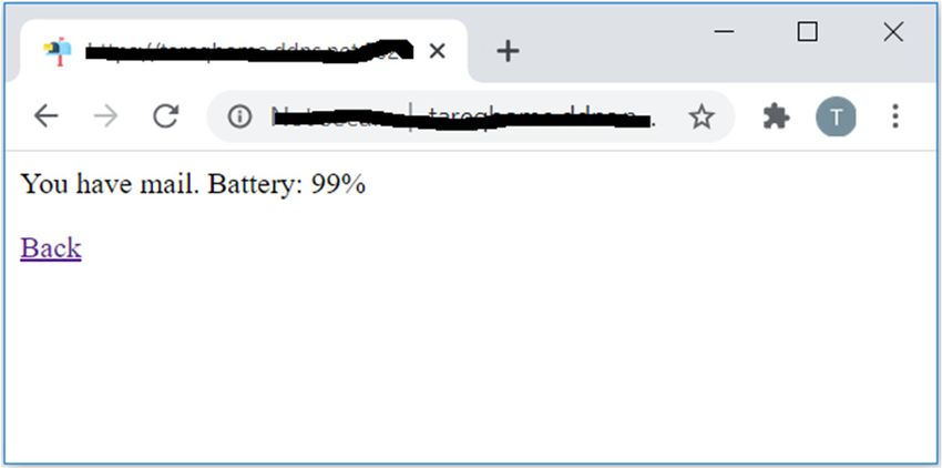
IoT 2020, 1                                                                                                          129

      In the proposed method, each smart mailbox contains a low power electronic device comprising
of a sensor for detecting the status of the mailbox door, a sensor to detect the presence of items inside
the mailbox, a system-on-chip microcontroller with Bluetooth Low Energy (BLE), and a rechargeable
lithium-ion polymer battery. The key design challenge of the electronic device is to make it consume
ultra-low power so that the battery can be charged using a solar panel without the need for manual
recharging. The proposed device is designed with low power consumption in mind and its battery is
charged with a solar panel, mounted on top of the mailbox. The device wakes up from low power
sleep mode whenever the mailbox door is closed, then it checks the presence of any item in the mailbox
and sends the data to a hub unit using BLE. Wireless systems, such as BLE, are easier to install than
wired systems. The hub is placed inside the home and it is wirelessly connected with the home Wi-Fi.
The hub then sends a push notification using the Internet to the owner’s smartphone. A smart speaker,
Google Home, is also interfaced with the system. When the owner asks Google Home: “Check physical
mailbox”, it answers “you have mail in your mailbox” or “your mailbox is empty”, depending upon
the status of the mailbox. Additionally, the status of the mailbox, whether empty or having mail, can be
read using a web browser from any place of the world.
      Several related works are found in the literature on developing a smarter mailbox. A comparison
with related works is shown in Table 1. In [8], a mail alert system is developed for centralized mailbox
systems using a programmable logic controller (PLC) and Global System for Mobile (GSM) modem.
Email or short message service (SMS) is generated to notify the user. However, the current consumption
of GSM modem in normal operation is 250 mA and can rise to 1 A while transmission [9]—thus, it will
require wiring of external power supply to the mailbox as the battery will not last long. Moreover,
the GSM modem will require a subscriber identity module (SIM) card, and the extra monthly payment
will also be required. The work in [10] is focused on digitizing building addresses and storing them in
Radio-frequency identification (RFID) tag, which can be used for drone delivery. The proposed mailbox
uses a passive infrared (PIR) motion sensor, cameras, solenoid locks, and RFID reader controlled by
an Arduino microcontroller with Wi-Fi connectivity. For security, the proposed mailbox captures an
image whenever a nearby motion is detected, and opens the mailbox lock when the user has the proper
RFID card. Due to the integration of camera, Wi-Fi, RFID reader, and solenoid, the power consumption
will be very high and battery or solar power charging might not be possible. Moreover, as there is no
sensor used to detect actual mail inside the mailbox, false alarms will be generated if someone moves
in front of the mailbox without the intention of checking or stealing mail.

                                       Table 1. Comparison with other works.

           Power           Solar         Door         Smart          Wireless
                                                                                                   Alert
         Consumption      Charging      Locking      Speaker          Link
  [8]          High          No            No          No              GSM                      Email/SMS
  [10]         High          No           Yes          No              Wi-Fi                       Email
                                                                 915 MHz TI radio
  [11]        Medium      Optional         No          No                                  Text, email, or Twitter
                                                                    transceiver
                                                                                     Smartphone notification only when
  [12]         Low           No            No          No              BLE
                                                                                      near the mailbox (not real-time)
  [13]         High           —           Yes          No              Wi-Fi              Smartphone Notification
  Proposed Low               Yes           No          Yes             BLE                Smartphone Notification
                  GSM, Global System for Mobile; BLE, Bluetooth Low Energy; SMS, short message service.

     Several startups are planning to make a commercial smart mailbox [11–13]. The work in [11] uses
915 MHz TI radio transceiver for communication, which consumes 45 mA during transmission [14].
In [12], notification to the smartphone is only sent when the user is close to the mailbox—thus,
the notification is not real-time. The work in [13] uses Wi-Fi-equipped Raspberry Pi (RPi) in the mailbox.
However, Rpi consumes more than 200 mA current during idle state and more than 300 mA current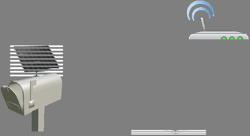
IoT 2019, 2 FOR PEER REVIEW 3
the notification is not real-time. The work in [13] uses Wi-Fi-equipped Raspberry Pi (RPi) in the
mailbox.
IoT 2020, 1 However, Rpi consumes more than 200 mA current during idle state and more than 300 mA
130
current when Wi-Fi is enabled [15]—thus, making it power-hungry and unsuitable for battery or solar
operated use. The Informed Delivery service [16] of the United States Postal Service (USPS) can send
when Wi-Fi is enabled [15]—thus, making it power-hungry and unsuitable for battery or solar operated
emails each morning containing the images of today’s mail. However, this does not provide
use. The Informed Delivery service [16] of the United States Postal Service (USPS) can send emails each
notification when the mail has arrived. Also, these emails do not contain images of mail from postal
morning containing the images of today’s mail. However, this does not provide notification when the
services other than USPS.
mail has arrived. Also, these emails do not contain images of mail from postal services other than USPS.
Compared with other works, the proposed work in this paper contributes to the following
Compared with other works, the proposed work in this paper contributes to the following points:
points:
• Ultra-low power consumption of the hardware as it uses BLE and event-based low power
• Ultra-low power consumption of the hardware as it uses BLE and event-based low power
firmware design.
firmware design.
• The mailbox contains recharging circuitry to charge the battery from a solar panel, thus, no manual
• The mailbox contains recharging circuitry to charge the battery from a solar panel, thus, no
charging nor is the wiring of power supply near the mailbox required.
manual charging nor is the wiring of power supply near the mailbox required.
•• The
The proposed
proposed mailbox
mailbox contains
contains aa sensor
sensor toto detect
detect mail
mail in in the
the mailbox,
mailbox, thus,thus, false
false alarms
alarms are
are not
not
generated if the mailbox door is opened without putting mail
generated if the mailbox door is opened without putting mail inside it. inside it.
•• The
The hub
hub in
in the
the proposed
proposed system
system connects
connects with
with the
the home
home Wi-Fi
Wi-Fi and
and cancan send
send aa notification
notification to
to the
the
smartphone to any place in the world in real-time.
smartphone to any place in the world in real-time.
•• The
The state-of-the-art
state-of-the-art smart
smart speaker,
speaker, Google
Google Home,
Home, isis interfaced
interfaced with
with thethe system
system which
which can
can speak
speak
the ofthe
the status of themailbox.
mailbox.ToTo date,
date, no related
no related work work is found
is found in theinliterature
the literature on interfacing
on interfacing smart-
smart-speaker
speaker with awith a mailbox.
mailbox.
•• The
The status
status of
of the
the mailbox
mailbox can
can also
also be
be viewed
viewed from
fromaaweb webbrowser
browserfrom fromany anyplace
placeofofthe
theworld.
world.
2. Materials and Methods
The overall system architecture of the proposed smart mailbox system system is shown
shown in Figure
Figure 1.
Whenever
Whenever the door of the mailbox is closed, the electronic device wakes-up
door of the mailbox is closed, the electronic device wakes-up from low power
power sleep
mode,
mode, senses
senses the existence
existence of mail inside the mailbox using infrared (IR) reflectance sensor,
sensor, and sends
the data to a hub using BLE. The device is powered from a rechargeable battery and it automatically
gets charged from
from aa solar
solarpanel.
panel.TheThehub—placed
hub—placed inside
inside thethe home—is
home—is wirelessly
wirelessly connected
connected with
with the
the
homehome Wi-Fi
Wi-Fi andand it sends
it sends a acloud
cloudmessage
messageusing
usingthethe Internet.
Internet. The
The smartphone
smartphone app app is notified
notified
immediately using push notification. The smartphone app also contains settings screen to configure
the hub wirelessly.
wirelessly. When
When aa customized
customized question
question is asked
asked toto Google
Google Home,
Home, which
which isis connected
connected with
with
the same
same home
home Wi-Fi
Wi-Fi network,
network, the
the hub
hub casts
casts audio
audio response
response toto Google
Google Home
Home depending
depending upon the
status of the mailbox.
mailbox. The hub acts as a web server and the status of the mailbox can also be viewed
from
from aa web
web browser.
browser.
(g) (d)
(c)
Wi-Fi Wi-Fi
BLE
(a) (b) (f) (e)
Figure 1.
Figure 1. The architecture of the
the smart
smart mailbox
mailbox system.
system. The smart mailbox (a), with the the electronic
electronic
device and
device and solar
solar panel,
panel, is connected
connected wirelessly
wirelessly with
with the
the hub
hub (b)
(b) using
using BLE.
BLE. The
The hub
hub is connected
connected with
the home
the homerouter
router
(c) (c) using
using Wi-Fi.
Wi-Fi. The sends
The hub hub cloud
sends message
cloud message
(d) using(d)
the using the
Internet Internet
to the to the
smartphone
app (e) whenever mail is arrived or removed. Google Home (f) is connected with the local Wi-Fi
network and can say the status of the mailbox. The status of the mailbox can also be viewed using a
web browser (g).IoT 2019, 2 FOR PEER REVIEW 4
IoT 2020,smartphone
1 app (e) whenever mail is arrived or removed. Google Home (f) is connected with the 131
local Wi-Fi network and can say the status of the mailbox. The status of the mailbox can also be viewed
using a web browser (g).
The key design challenges of this IoT system are reducing the power consumption, range of
wirelessThedevices, real-time
key design notification,
challenges reliability,
of this IoT system and smart speaker
are reducing interfacing.
the power The rest
consumption, rangeofofthis
section discusses
wireless devices,the different
real-time components
notification, of the and
reliability, system, and
smart how the
speaker challenges
interfacing. Theare
restaddressed
of this
and implemented.
section discusses the different components of the system, and how the challenges are addressed and
implemented.
2.1. Smart Mailbox
2.1.The
Smart Mailbox
smart mailbox detects the presence of mail inside it and sends the data to the hub, whenever
the door of smart
The the mailbox is closed.
mailbox A microcontroller-based
detects the presence of mail insidehardware device
it and sends is designed
the data for this
to the hub, purpose.
whenever
Thethekey design
door challenge
of the mailbox ofis the hardware
closed. is lowering the power
A microcontroller-based consumption,
hardware as it is powered
device is designed for this by
purpose.and
a battery Therecharged
key design challenge
using a solarofpanel.
the hardware is lowering
The hardware the powerof
and firmware consumption,
the device are as briefly
it is
poweredbelow.
described by a battery and recharged using a solar panel. The hardware and firmware of the device
are briefly described below.
2.1.1. Hardware
2.1.1. Hardware
The block diagram of the hardware unit inside the smart mailbox is shown in Figure 2.
The block diagram of the hardware unit inside the smart mailbox is shown in Figure 2.
3.3V Vcc
IR reflectance
390kΩ
sensor
nRF52840
SoC with BLE GND
Solar Charger
Power
Solar Panel nRF52 Feather
Express Board 1µF
Li-Po 1kΩ
Battery 2N2222A Tilt
Sensor
Figure2.2.Block
Figure Block diagram
diagram of
of the
the smart
smartmailbox
mailboxhardware
hardwaredevice.
device.
Nordic
Nordic nRF52840
nRF52840 [17]
[17] is is a low-power,
a low-power, small-size
small-size system-on-chip
system-on-chip (SoC)
(SoC) micro-controller
micro-controller with
with BLE,
BLE, and it is used as the processing and wireless communication unit. The
and it is used as the processing and wireless communication unit. The micro-controller incorporates micro-controller
anincorporates an industry-standard ARM Cortex M4F microprocessor, 1 MB in-system programmable
industry-standard ARM Cortex M4F microprocessor, 1 MB in-system programmable flash memory,
flash memory, 256 kB RAM, 2.4 GHz BLE 5 transceiver having output power up to +8 dBm, 6 analog-
256 kB RAM, 2.4 GHz BLE 5 transceiver having output power up to +8 dBm, 6 analog-to-digital converter
to-digital converter (ADC) channels, general-purpose input/output (GPIO), Timer, I2C, and many
(ADC) channels, general-purpose input/output (GPIO), Timer, I2C, and many different peripherals.
different peripherals. Its low-power sleep modes are appropriate for systems where ultra-low power
Its low-power sleep modes are appropriate for systems where ultra-low power consumption is required
consumption is required to extend battery life. BLE 5 has a maximum data rate of 48 Mbps and
to extend battery life. BLE 5 has a maximum data rate of 48 Mbps and distances up to 300 m. It also
distances up to 300 m. It also introduces a new mode of operation, known as the long-range mode,
introduces a new mode
that can transmit of operation,
data from a distanceknown
of 1.6 km the long-range mode, that can transmit data from a
as[18].
distance of 1.6 km [18].
A Feather nRF52840 Express [19] board is used in this project, which consists of the nRF52840
A Feather nRF52840
microcontroller, The board Express [19] boardconverter
has a USB-Serial is used inforthis project, which
programming, consistsforof3.7
a connector theV nRF52840
lithium
microcontroller, The board has a USB-Serial converter for programming, a connector
polymer (Li-Po) battery, onboard 3.3 V regulator, and a battery charging circuit. The programming for 3.7 V lithium
polymer (Li-Po) battery, onboard 3.3 V regulator, and a battery charging circuit.
and charging circuits only get power when the board is connected with USB and no longer consume The programming
and charging
power whencircuits onlyisget
the battery power when
connected only. the
Whenboard
bothisbattery
connected withare
and USB USB and no longer
connected, consume
the charging
power when
circuit startsthe batterythe
to charge is connected
battery from only.
USBWhen
power.both batterydivider
A voltage and USB are connected,
circuit—that the charging
is powered from
circuit starts to charge the battery from USB power. A voltage divider circuit—that is powered from
the battery connector—is implemented on the Feather board, and its middle point is connected to an
ADC pin of the microcontroller—to monitor the voltage level of the battery.IoT 2020, 1 132
A 6-watt solar panel [20] is connected with a solar charger module [21] to charge the battery
whenever sunlight is available. A 3.7V Li-Po rechargeable battery [22] having a capacity of 2500 mAh
is connected with the battery terminal of the solar charger module. The module uses the LT3652
monolithic chip that implements maximum power point tracking (MPPT) method for single-cell Li-Po
battery, capable of charging at a rate of maximum 2 A. For this application, the maximum charge
current is set to 450 mA.
A tilt sensor switch [23] is used to detect the door position of the mailbox—whether it is closed,
having a vertical orientation, or it is open, having a horizontal orientation. When the sensor is upright,
a metal ball inside the sensor makes contact with the sensor terminals; when the sensor is tilted,
the metal ball disconnects the terminals. The sensor is placed on the mailbox door in an angular
orientation so that, whenever the door is closed, the sensor terminals are open, and whenever the
door is open, the sensor terminals are closed. The sensor is connected to a GPIO interrupt pin of
the microcontroller and the interrupt is configured at the rising event. A 1 µF capacitor is connected
from the MCU pin to the ground to filter out the bounce signal from the sensor. An external pull-up
resistor of 390 kΩ—as shown in Figure 2—is used to make the pin high when the sensor terminals
are open. Internal pull-up resistors (Rpu ), having a value of approximately 13 kΩ, are available in
the nRF52832 [17]. However, enabling the internal pull-up resistors will cause this branch through
the switch to continuously consume 3.3÷13k = 0.25 mA current whenever the sensor terminals are
closed. This significant current will quickly reduce battery life. So, a higher value external pull-up
resistor of 390 kΩ is used by disabling the internal pull-up resistors. With this solution, the branch
consumes only 3.3 ÷ 390k = 8.46 µA current (measured 8.32 µA in real-time) when the sensor terminals
are closed. If a higher value of external resistor such as 1 MΩ is used, then too much voltage drops,
and the microcontroller pin does not recognize an interrupt event. That is why a resistor of 390 kΩ
external pull-up resistor is used—which is less than 1 MΩ and larger than the internal pull-up of
13 kΩ. The microcontroller input pin sinks insignificant current as the input resistance of the pin is
high. When the mailbox door is closed: the sensor terminals are opened, the microcontroller pin goes
from low to high and triggers a rising interrupt event.
A miniature IR reflectance sensor, QRE1113 breakout board [24], is used to detect the existence
of mail in the mailbox. The sensor is comprised of two parts—an IR emitting light-emitting diode
(LED) and an IR sensitive phototransistor. When power is applied to the breakout board, the IR LED
of the sensor lights up. The output voltage of the sensor goes from high to low when the IR from
the LED is reflected on the phototransistor. The higher the IR light is sensed by the phototransistor,
the lower the output voltage of the breakout board. The output pin is connected with an ADC pin
of the microcontroller. When mail is put in the mailbox: it covers the sensor, the IR gets reflected by
the mail, more IR is sensed by the phototransistor, and output voltage becomes lower. The sensor is
cut off from power when it is not used to reduce power consumption. To connect and disconnect the
sensor’s ground pin from the power supply ground, an NPN transistor [25] is used. A GPIO pin of the
microcontroller, as shown in Figure 2, controls the base of the transistor. The base current flows only
for a few milliseconds during stabilization and sensing, and then the current is made zero by turning
the GPIO pin to low, to cut off the power from the sensor.
2.1.2. Firmware
The electronic device, placed in the smart mailbox, sends data to the hub using BLE. The mailbox
device acts as peripheral and the hub acts as central [26]. A feature-rich BLE 5 protocol stack for the
nRF52840 SoC—referred to as SoftDevice—is implemented that contains complete stack with Generic
Access Profile (GAP), Generic Attribute Profile (GATT), Link and other layers [27]. The BLE protocol
supports custom data transmission either using advertisements in a non-connected state or using
services in a connected state. To transmit data in a connected state, the firmware must use a service
and the service must contain one or more characteristics [26]. Services are used to break data in
groups and each group contains specific chunks of data called characteristics. A service can haveIoT
IoT 2019,
2020, 21 FOR PEER REVIEW 6
133
or more characteristics, and each service distinguishes itself from other services using a unique
one or more
numeric characteristics,
ID called a Universally andUnique
each service distinguishes
ID (UUID), which can itselfbefrom
eitherother16-bitservices using aadopted
(for officially unique
numeric ID called a Universally Unique ID (UUID), which can be either
BLE Services) or 128-bit (for custom services). Like services, each characteristic distinguishes itself 16-bit (for officially adopted
BLEa Services)
via pre-defined or 128-bit
UUID. Custom (for custom services).
service Like services,
is implemented by theeach characteristic
firmware in the GATT distinguishes itself
profile. Under
via aservice,
this pre-defined UUID.
a custom Custom service
characteristic is implemented
is created. The data by the firmware
length in the GATTisprofile.
of the characteristic Under
2 bytes—one
this service,
byte to indicate a custom characteristic
the existence of mailisand created.
another Thebytedatafor length
batteryof the characteristic
level. is 2 bytes—one
The notify property of the
byte to indicate
characteristic theso
is set existence
that a call of back
mail function
and another in thebytehub foris battery level. The notify
called automatically property
whenever theofdata
the
characteristic
in is set so
the characteristic is that a call back function in the hub is called automatically whenever the data in
updated.
the characteristic is updated.
To make a connection with the hub, the device first advertises with its GAP data. Then the hub
To make a with
gets connected connection
the devicewithandthe hub,
remains the device first advertises
at the connected state.with
The its BLE GAP data. Then
transmit powerthe of hub
the
device is set to its maximum value of +8 dBm. Once connected, the device stops advertising andthe
gets connected with the device and remains at the connected state. The BLE transmit power of it
device isready
becomes set toforits data
maximum value of
transmission. +8 BLE
If the dBm.is Once connected, thetodevice
disconnected—due low batterystopsor advertising
range issues— and
ait BLE
becomes ready for
disconnected data
call backtransmission.
function is called If theinBLE is disconnected—due
the hub and the device starts to low battery again
advertising or range for
issues—a
reconnection. BLE disconnected call back function is called in the hub and the device starts advertising
againThe for firmware
reconnection. uses a real-time operating system (RTOS)—referred to as FreeRTOS [28]. Instead
The firmware
of always running codesuses a inside
real-time operating
a loop, system (RTOS)—referred
the firmware executes call back to as FreeRTOS
functions [28]. Instead
on events to save
of always
power. Therunning
firmware codeswaitsinside
for ana loop,
eventthe to firmware
happen toexecuteswake upcall and backthen functions
again goes on events
to low to save
power
power.mode.
sleep The firmware
Whenever waitsthefor an event
mailbox to happen
door is closed, to wake up and
the tilt sensorthenbecomes
again goes open,to lowthepower sleep
door_closed
mode. Whenever
interrupt the mailbox
is triggered, and thedoor is closed, thewakes
microcontroller tilt sensor
up. becomes
The interrupt the door_closed
open, service routine interrupt
(ISR) then is
triggered,
starts a timerand andthealso
microcontroller
applies powerwakes to theup. The interrupt
IR reflectance sensorservice routinethe
by making (ISR)
GPIO thenpinstarts
high,awhich
timer
and
is also applies
connected withpower
the base to the IR reflectance
of the transistor. Duringsensor by themaking
delay from the GPIO pin high,
the timer, which isisconnected
the mailbox expected
with
to the base
become of the
stable from transistor.
motion. During
After the the delaythe
delay, from theISR
timer timer, the mailbox
is called. In thisisISR, expected to become
the timer is first
stable from
stopped. Then motion.
the ADC After the delay,
peripheral the timerIRISR
is enabled, is called.sensor
reflectance In this ISR,and
data thebattery
timer is first are
levels stopped.
read,
Thenthe
then theADC
ADCperipheral
peripheralisisdisabled.
enabled, The IR reflectance
IR reflectance sensor datadata
sensor andisbattery
compared levels are aread,
with then the
threshold to
ADC peripheral
determine whether is disabled.
mail is inThe theIRmailbox.
reflectance Thesensor
existencedataofis mail
comparedand the with a threshold
battery level datato determine
are then
whetheron
written mailtheisBLE
in the mailbox. The existence
characteristics—causing the ofexecution
mail and the of abattery
call-back level data are
function inthen written
the hub on the
to receive
BLE characteristics—causing
the data. Lastly, the power is cut off from the IR reflectance sensor by making the GPIO pinLastly,
the execution of a call-back function in the hub to receive the data. low,
the power
which is cut
controls theofftransistor.
from the IR reflectance
Then the program sensor bytomaking
goes sleep modethe GPIO pin low,
and waits for which
anothercontrols
door close the
transistor.
event Then the
to happen. Theprogram goes to sleep
actions executed by the modedevice and waits
after thefor
dooranother
of thedoor mailboxcloseisevent
closedtoishappen.
shown
The
in actions
Figure 3. executed by the device after the door of the mailbox is closed is shown in Figure 3.
Start
Disable ADC
Connect power to the IR reflectance
sensor Compare sensor data with a threshold
to determine existence of mail
Start timer - for the mailbox to get
stable from motion
Send data to the hub by writing to the
BLE characteristics
Stop timer
Detach power from IR reflectance
Enable ADC
sensor
Read IR reflectance sensor and Go to low power sleep mode and wait
battery level data using ADC for next event
End
Figure 3. Flowchart
Flowchartof
ofactions
actionsafter
after
thethe door
door of mailbox
of the the mailbox is closed.
is closed. IR, infrared;
IR, infrared; ADC, analog-to-
ADC, analog-to-digital.
digital.IoT 2020, 1 134
In the firmware, the following configurations are done to reduce the power consumption:
• Instead of using the low dropout (LDO) regulator, the DC/DC converter of the microcontroller is
used to decrease power consumption [29].
• The floating-point unit (FPU) consumes significant power. So, the program was written avoiding
any floating-point number. The exception flags and the pending FPU interrupts were cleared to
take the microcontroller in low power mode [30].
• The RTOS uses a tick interrupt to measure time. The increase of the tick frequency means that the
timer can measure time to a higher resolution, and vice versa. The RTOS scheduler also shares
processor time between tasks of the same priority by switching between the tasks during each
RTOS tick. The tick rate frequency affects the time slice given to each task [28]. To reduce power
consumption, the frequency of the RTOS tick interrupt (referred to as configTICK_RATE_HZ)
was decreased from 1024 Hz to 64 Hz and it reduced 110 µA current. Further decreasing the
tick frequency causes problems in the ADC peripheral. The system clock of the microcontroller
(referred to as SystemCoreClock) is 64 MHz and it is not changed. Thus, the microcontroller does
not sacrifice its performance and executes instructions at a high speed.
2.2. The Hub
The hub receives data from the mailbox using BLE and sends a cloud message using the home
Wi-Fi to the smartphone app. The smart speaker and web interface also connects with the hub using
the home router. The hub can be placed inside the home, within the range of the BLE and home Wi-Fi
signal. The hardware and app parts of the hub are described below.
2.2.1. Hardware
A single-board computer, Raspberry Pi (RPi) v3 [31], is used as the main processing unit. It contains
a 64-bit quad-core ARMv8 microprocessor running at 1.2 GHz, 1 GB of RAM, a micro SD card slot
supporting up to 32 GB, on-board BLE, Wi-Fi module, and other built-in hardware peripherals. A 110 V
AC to 5.1 V DC adapter [32] is used as the power supply for the RPi board.
2.2.2. Network Configuration
The hub must be accessed from outside of the home network using the Internet, to interface it
with a smart speaker, get mailbox status from a web browser, and to update its settings from the
smartphone. So, the hub is made a Hypertext Transfer Protocol (HTTP) server, which can receive
and send data from/to the Internet using the transmission control protocol/Internet protocol TCP/IP.
To access the server, it should have a fixed address and a port number. The local (or private) IP of the
hub is dynamically assigned by the dynamic host configuration protocol (DHCP) server of the router;
thus, the IP address of the hub may change on a new connection depending on how many devices are
currently connected with the router. To solve this, the local IP of the hub is made static [33] and port
forwarding [34] is configured in the router. The port forwarding mechanism will transmit the data
packet, which arrives at the home router from the Internet, to the hub’s HTTP server. A friendly and
memorable name for the home router’s public IP address is assigned using a free dynamic domain
name system (DDNS) [35] server. The public IP of the home router—assigned by the Internet service
provider (ISP)—does not change frequently, but may change after months or years. To solve this
problem, the router is configured by entering the DDNS provider’s login information. This ensures
that the public IP address in the DDNS server is automatically updated if it changes [36].
Note that the setting of the hub IP as static can also be done using a python program without
manually configuring the router. The hub firmware may contain a function to write in the/etc/dhcpcd.conf
file as described in [37] to set its IP as static. Other router configurations can also be done from the
python program using libraries such as roscraco [38], which will eliminate the need for configuring the
router manually. We plan to automate the router configuration in the future.IoT 2020, 1 135
IoT 2019, 2 FOR PEER REVIEW 8
2.2.3. Firmware
Raspberry Pi OS (previously called Raspbian) [31]—a Debian-based Linux operating system—is
Raspberry
installed on a 16 Pi GB
OS SD(previously
card of the RPi Raspbian)
called board. The [31]—a
firmwareDebian-based
is developed Linux operating
in Python system—is
language and
installed on a 16 GB SD card of the RPi board. The firmware is developed
the necessary packages such as pygatt, pyfcm, pychromecast, http.server are installed. in Python language and the
necessary packages
At startup, the such
hub as pygatt,
gets pyfcm, to
connected pychromecast,
the home http.server
router using are Wi-Fi
installed.
and thus can access the
Internet. The last saved status of the mailbox and some settings—such and
At startup, the hub gets connected to the home router using Wi-Fi as thethus can access
presence the Internet.
of mail, battery
The last saved status of the mailbox and some settings—such as the
level, Goggle Home Internet Protocol (IP) address, and BLE media access control (MAC) address— presence of mail, battery level,
Goggle
are loadedHomefrom Internet Protocol file.
the settings.dat (IP) The
address, and BLE
hub then mediawith
connects access
thecontrol
mailbox (MAC)
usingaddress—are
BLE and subscribesloaded
from the settings.dat file. The
to the custom characteristic’s UUID. hub then connects with the mailbox using BLE and subscribes to the
custom characteristic’s UUID.
Whenever the door of the mailbox is closed, the mailbox’s status is sent to the hub using BLE,
and aWhenever
call back the door of the mailbox
function—BLE is closed,called
data arrival—is the mailbox’s
in the hub.status
Theis sent to the
actions hub using
executed BLE,
after theand
huba
call back function—BLE data arrival—is called in the hub. The actions
receives the BLE data are shown in Figure 4. In the BLE data arrival function, the status of theexecuted after the hub receives
the BLE data areas
mailbox—such shown in Figure 4.
the presence the BLE
of Inmail, data arrival
battery level, function,
and BLEthe status of the
connection mailbox—such
status—is saved in as
the presence of mail, battery level, and BLE connection status—is saved in settings.dat
settings.dat file and is sent to the user’s smartphone using Firebase Cloud Messaging (FCM) [39]. FCM file and is sent to
the user’s smartphone using Firebase Cloud Messaging (FCM) [39]. FCM
is a cross-platform messaging solution that reliably sends messages at no cost using the Internet.is a cross-platform messaging
solution
Using thatareliably
FCM, smartphonesendsapp messages at no cost using
can be immediately the Internet.
notified whenever Using
new FCM,data isaavailable
smartphone app
to sync.
can be immediately notified whenever new data is available to sync.
A message can carry a payload of a maximum of 4 KB to a client app. The message is sent using aA message can carry a payload
of a maximum
Server key that isofgenerated
4 KB to afromclientthe
app. Theserver
cloud message where is sent
the using a Server
smartphone appkeyisthat is generated
registered. If thefrom
BLE
the cloud server where the smartphone app is registered. If the BLE connection
connection with the mailbox is disconnected—due to low battery or range issues—a BLE disconnected with the mailbox is
disconnected—due to low battery or range issues—a BLE disconnected call
call back function is called in the hub. The function then updates the smartphone about the BLE back function is called in the
hub. The function
disconnected statusthen
using updates
FCM. the smartphone about the BLE disconnected status using FCM.
Start
Get the mailbox status by reading
from the BLE characteristics
Save data in file
Send firebase cloud message
containing the status of the mailbox
to the user's smartphone
End
Figure
Figure 4.
4. Flowchart
Flowchart of
of actions
actions after
after the
the hub
hub receives
receives the
the BLE
BLE data.
data.
An HTTP server is implemented in the firmware. Whenever Whenever an an HTTP
HTTP GET
GET request
request toto the
the server
server
is made,
made, aa call
callback
backfunction
functionis is
called in in
called thethe
firmware.
firmware.TheThe
server of the
server of hub
the needs to be to
hub needs accessed using
be accessed
the Internet:
using to configure
the Internet: its settings
to configure fromfrom
its settings a smartphone—as
a smartphone—as the the
hubhubdoes notnot
does have anyany
have display
displayor
keyboard,
or keyboard,to get the mailbox
to get status
the mailbox in theinsmartphone,
status to get to
the smartphone, theget
mailbox status from
the mailbox a web
status frombrowser,
a web
and to sayand
browser, thetostatus of the
say the mailbox
status of theusing a smart
mailbox speaker.
using a smartThe Uniform
speaker. TheResource
UniformLocator (URL)
Resource of the
Locator
GET requests
(URL) of the GETcontains the words
requests listed
contains thebelow.
wordsThe hub
listed executes
below. Thethe
hub following
executesactions upon receiving
the following actions
these receiving
upon requests: these requests:
•• Settings:This
Settings: Thisrequest
requestisis made
made byby
thethe smartphone
smartphone app.
app. The The
URLURL of request
of this this request consists
consists of the of
MACthe
MAC address of the smart mailbox’s BLE and the local IP address of Google Home.
address of the smart mailbox’s BLE and the local IP address of Google Home. Once the hub getsOnce the hub
gets request:
this this request: the BLE
the BLE MACMAC and and the Google
the Google HomeHome IP address
IP address are are parsed
parsed from
from thethe
URL,URL, saved
saved in
in the
the settings.dat
settings.dat file,
file, reconnect
reconnect with
with mailboxusing
mailbox usingthe
thenew
newBLE
BLEMAC,
MAC,and and send
send the
the mailbox
mailbox
status—the presence of mail, battery level, and BLE connection status—to
status—the status—to the smartphone
smartphone app app
using FCM.
• Status: This request is made by the smartphone app to get the current status of the mailbox. When
this request is received, the hub sends the mailbox status to the smartphone using FCM.IoT 2020, 1 136
• Status: This request is made by the smartphone app to get the current status of the mailbox. When
this request is received, the hub sends the mailbox status to the smartphone using FCM.
• Web: This request can be made by the user from any web browser to get the status of the mailbox.
The hub responds to this request by sending an HTML message—containing whether mail is
present in the mailbox and the battery charge level—to the web browser.
• Voice: This request is made by the If This Then That (IFTTT) [40] web service to interface with
the Google Home smart speaker. This request is made whenever the user asks Google Home to
“check the mailbox.” Upon receiving this request: the hub creates a new thread for casting audio
to Google Home, connects with Google Home using its IP, and casts audio “you have mail in your
mailbox” or “your mailbox is empty”—depending upon the status of the mailbox. These two
audio mp3 files are uploaded in Firebase Cloud Storage [41] and the hub access these files using a
secure URL. This audio casting is done using a python library named pychromecast [42].
2.3. Smartphone App
The smartphone app is developed for the Android platform. When the app starts, it sends an
HTTP GET request to the hub’s server using the status word in the URL. The hub then sends the status
of the mailbox using FCM to the smartphone. The first screen of the app shows the status of the
mail—“you have mail” or “mailbox is empty;” the percentage of battery charge level; date and time of
the last data update; its connection status with the hub using the Internet; and the hub’s connection
status with the mailbox using the BLE. It also contains a button to reconnect with the mailbox using
BLE and it is enabled when the connection of the hub with the mailbox is lost.
The app contains a settings menu for configuring notifications, the hub’s public IP, Google Home
IP, and mailbox’s BLE MAC. The user can enable or disable notifications: at the event of a new mail,
at the event of when the mailbox is empty, or both. It might be necessary to get a notification when the
mail is taken out and the mailbox becomes empty to detect mail theft. To make an HTTP request to
the hub from the smartphone app, the public IP, or the friendly name of the hub server is required.
If the smartphone is connected with the same Wi-Fi network of the hub, then the public IP of the Wi-Fi
network can be autofilled by pressing a button that sends an HTTP request to https://ipecho.net/plain
and it responds the IP from where the request was made. Alternatively, the public IP can also be
manually entered by looking it up from the whatsmyip.com website. To audio cast the status of the
mail to the smart speaker, the hub must know the Google Home IP. The user enters the Google Home
IP in the app. Google Home IP can be found from the Home app [43]. The hub must know the BLE
MAC for connecting with the mailbox. To get the BLE MAC of the mailbox, the user presses the ‘Start
Scan’ button to find the nearby BLE devices that are advertising. The nearby BLE devices are added in
a list-view box and the user can select the required MAC address from the list. Once the user exits
from the settings menu by pressing the back button, the app saves the data in settings.dat file and sends
an HTTP GET request to the hub using the settings word, the BLE MAC, and the Google Home IP in
the URL.
The first screen of the app is updated whenever a new FCM message arrives. The flowchart in
Figure 5 shows the actions taken by the smartphone whenever the FCM message is received. In this
way, the data is synchronized between the hub in the home and the user’s smartphone—at whatever
place the user may be in the world. The app is added and registered in the FCM for receiving the
push notification. A service, named FirebaseMessaging, runs at the background of this app. When it
receives a push notification message from the FCM, a call back function is called and the app saves
the mailbox status—such as the presence of mail, battery level, and BLE connection status—with the
current date/time information in the status.dat file. The app then generates a smartphone notification
if new mail arrived or the mail is removed, depending on the notification settings and last status.
The first screen of the app is then updated to show the current status of the mailbox and battery level.
If the hub’s BLE connection with the mailbox is lost, then the connection status of the mailbox is shown
as “disconnected;” and the presence of mail and battery level is shown as unknown.IoT 2020, 1 137
IoT 2019, 2 FOR PEER REVIEW 10
Start
Parse mailbox status from cloud
message
Save status in file
Generate notification
Update mailbox status on screen
End
Figure 5. Flowchart of actions when the Firebase Cloud Messaging (FCM) message is received.
Figure 5. Flowchart of actions when the Firebase Cloud Messaging (FCM) message is received.
If
If the
the hub
hub server
server is
is down,
down, then
then any
any HTTP
HTTP request
request sent
sent from
from the
the smartphone
smartphone will
will result
result an
an error
error
message. In this case, the connection status of the hub is shown as “disconnected” and the presence
message. In this case, the connection status of the hub is shown as “disconnected” and the presence
of
of mail,
mail, battery
battery level,
level, and
and BLE
BLE connection
connection status
status with
with the
the mailbox
mailbox are
are shown
shown as
as unknown
unknown inin the
the first
first
screen of the app.
screen of the app.
2.4. Smart
Smart Speaker
Speaker Interface
Interface
A smart speaker, Google Home, is interfaced with the system. When When thethe user
user asks
asks Google
Google Home:
Home:
“Ok Google,
“Ok Google, check
checkphysical
physicalmailbox”,
mailbox”,ititanswers
answers“you
“youhavehavemail
mailininyour
yourmailbox”
mailbox” oror “your
“your mailbox
mailbox is
is empty”,
empty”, depending
depending uponthe
upon thestatus
statusofofthe
themailbox.
mailbox.ThisThiscustomized
customized question
question is implemented using
an IfIf This
ThisThen
ThenThat
That(IFTTT)
(IFTTT)[40]
[40]applet.
applet.Simple
SimpleIFTTT
IFTTTapplet cancan
applet recognize customized
recognize questions
customized and
questions
can
and answer
can answera static response,
a static but itbut
response, cannot choose
it cannot fromfrom
choose a seta of
setanswers based
of answers on sensor
based on sensor input. To
input.
solve
To solve thisthis
problem,
problem,thetheaction
actionofofthe applet
the appletisismade
madetotobebea aweb
webrequest
requestusing
usingWebhooks
Webhooks [44]. IFTTTIFTTT
makes an HTTP GET request to the hub’s friendly name and port number with the word voice in the
URL. After
After this
this request
request is is received,
received, the
the hub
hub first
first connects
connects with
with the
the Google
GoogleHome
Homeusing
usingits itslocal
localIP.
IP.
The Google
Google HomeHomeIP IPisismade
madestatic
staticbybyconfiguring
configuring the router. Then, depending upon the
the router. Then, depending upon the status of thestatus of
the mailbox,
mailbox, the the
hubhub casts
casts thethe audio—“you
audio—“you have
have mail
mail in your
in your mailbox”
mailbox” or or “your
“your mailbox
mailbox is is empty”—
empty”—to
to
thethe smart
smart speaker.
speaker.
Web Interface
2.5. Web Interface
The status of the mailbox—whether empty or
mailbox—whether empty or having
having mail—can
mail—can be be read
read using
using a web browser
from any place of the world. An An index.html
index.html file
file was
was placed
placed in the same folder of the hub’s python
code—running the HTTP server.
server. The website can be accessed using the public IP or the friendly
friendly name
name
of the hub using any web browser from any place of the world. The website is written using HTML
and it contains a hyperlink—“Get status”. When
When thethe user
user clicks
clicks it,
it, it
it makes an HTTP GET request to
the hub’s friendly
friendlyname
nameand
andport
portnumber
numberwith
withthe word
the wordweb in in
web thethe
URL. TheThe
URL. hubhub
thenthen
responds to this
responds to
request by sending an HTML message—containing whether mail is present in the
this request by sending an HTML message—containing whether mail is present in the mailbox and mailbox and the
battery
the charge
battery level—to
charge the web
level—to browser.
the web browser.
3. Results
3. Results
A prototype
A prototypeofofthe
theproposed
proposedsmart
smartmailbox,
mailbox,thethe
hub, smartphone
hub, app,
smartphone Google
app, Home
Google interface,
Home and
interface,
web web
and interface has been
interface developed
has been and and
developed tested successfully.
tested A photograph
successfully. of the
A photograph ofsmart mailbox—with
the smart mailbox—
the electronic device inside it—is shown in Figure 6. The current consumption of the device
with the electronic device inside it—is shown in Figure 6. The current consumption of the at adevice
different
at
a different state was measured using an ammeter and shown in Table 2. The BLE of the device will
advertise only when it needs to be discovered by the hub. Once discovered and connected, the deviceIoT 2019, 2 FOR PEER REVIEW 11
consumes 780 µA current. The mailbox will be at this low power idle state most of the time. When
the door is opened and then closed, the device wakes up from sleep mode, senses the presence of the
mail
IoT and
2020, 1 transmits data for a short amount of time for few milliseconds, and again goes to sleep 138
mode. The prototype uses a Li-Po rechargeable battery having a capacity of 2500 mAh and it is
connected with a solar panel through a solar charger circuit. Whenever sunlight is available, the
state waswill
battery measured using an
be charging. ammeter no
Assuming andsolar
shown in Tableis2.available,
charging The BLE of thebattery
the devicelife
willofadvertise onlyis
the device
when it needs to be discovered by the hub. Once discovered and connected, the
approximately 2500 ÷ 0.78 = 3205.12 h or 133 days. So, the smart mailbox will work even if the weather device consumes
780 µA current.
is cloudy for manyThedays.
mailbox willbattery
As the be at this
willlow power idle
be charging statethe
during most of the time.
daytime, When the
the proposed door
mailbox
iswill
opened and then closed, the device wakes up from
not run out of power and no manual charging will be required. sleep mode, senses the presence of the mail
and transmits data for a short amount of time for few milliseconds, and
The photograph of the hub—that is placed inside the house—is shown in Figure 7. The again goes to sleep mode.
The prototype
screenshots of uses a Li-Po rechargeable
the smartphone app are shownbattery having8.a The
in Figure capacity of 2500ofmAh
first screen andshows
the app it is connected
the status
with a solar panel through a solar charger circuit. Whenever sunlight is available, the
of the mail; the percentage of battery charge level; date and time of the last data update; its connection battery will
be charging.
status Assuming
with the hub; thenohub’s
solar connection
charging is status
available,
withthe
thebattery
mailboxlifeusing
of thethedevice
BLE;isand
approximately
a button to
2500
reconnect = 3205.12
÷ 0.78the hub with h orthe
133mailbox
days. So, if the
the smart mailbox
connection will work
is lost. The appeven if the weather
generates is cloudy
notifications for
when
many days. As the battery will be charging during the daytime, the proposed
mail arrives, or mail is removed. The status of the mailbox can be known by asking Google Home mailbox will not run out
of power
smart and noand
speaker manual charging
also using a webwill be required.shown in Figure 9.
browser—as
5
4 3
1
2
(a) (b) (c)
Figure6.6.Photograph
Figure Photograph of ofthethesmart
smartmailbox:
mailbox: (a)
(a)electronic
electronicdevice
deviceplaced
placedinside
insidethe
themailbox—(1)
mailbox—(1)IR IR
reflectance
reflectancesensor,
sensor,(2)
(2)tilt
tiltsensor,
sensor,(3)
(3)system-on-chip
system-on-chip(SoC)(SoC)microcontroller
microcontrollerwith
withBLE,
BLE,(4)
(4)solar
solarcharger
charger
and
andLi-Po
Li-Porechargeable
rechargeable battery, and (5)
battery, andsolar
(5) panel; (b) mail(b)
solar panel; in the mailbox—covering
mail the IR reflectance
in the mailbox—covering the IR
sensor; (c) when
reflectance the door
sensor; is closed,
(c) when thethedoor
tilt sensor causesthe
is closed, an interrupt to the
tilt sensor microcontroller.
causes an interrupt to the
microcontroller.
Table 2. Measured current consumption of the device at different states.
Table 2. Measured
Devicecurrent
State consumption of theConsumption
Current device at different
(µA) states.
BLE advertising
Device State 630–900
Current Consumption (µA)
BLE connected and idle 780
BLE advertising 630–900
Sensing and transmitting 22,300
BLE connected and idle 780
Sensing and transmitting 22,300
The photograph of the hub—that is placed inside the house—is shown in Figure 7. The screenshots
of the smartphone app are shown in Figure 8. The first screen of the app shows the status of the mail;
the percentage of battery charge level; date and time of the last data update; its connection status with
the hub; the hub’s connection status with the mailbox using the BLE; and a button to reconnect the hub
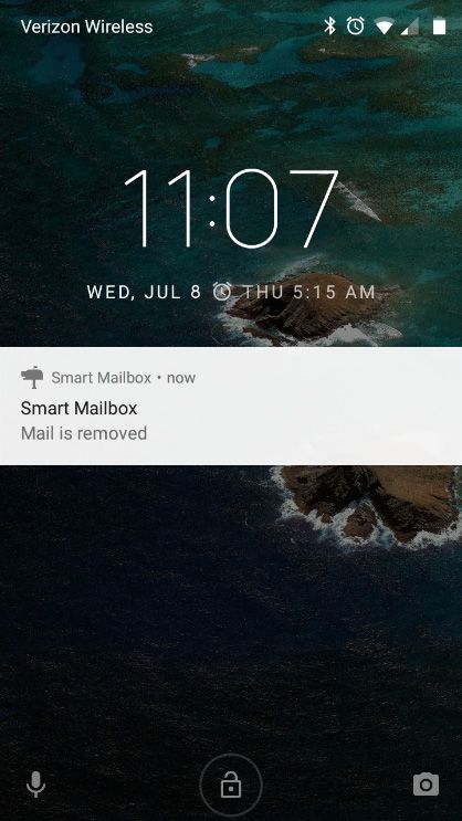
with the mailbox if the connection is lost. The app generates notifications when mail arrives, or mail is
removed. The status of the mailbox can be known by asking Google Home smart speaker and also
using a web browser—as shown in Figure 9.
The smart mailbox system was tested in the real world by putting the mailbox around 100 feet
away, across a 30-foot street, from the hub. The hub was placed inside the home about 3 feet high
from the ground. When mail was put and the door of the mailbox was closed, the mailbox status
was updated immediately on the smartphone app. The smart speaker could answer the status of theIoT 2020, 1 139
mailbox and the status could also be read using a web browser. We also took the smartphone out
of the range of home Wi-Fi and it was connected with the Internet using the cellular network. The
smartphone successfully received notification in this scenario also.
IoT 2019, 2 FOR PEER REVIEW 12
IoT 2019, 2 FOR PEER REVIEW 12
Figure 7. Photograph
Figure Photographof
7. Photograph the
ofof
the hub—implemented
hub—implemented
the in
in aa Raspberry
hub—implemented Raspberry Pi board.
in a Raspberry Pi board.
(a) (b) (c)
Figure
Figure 8. 8. Screenshots
Screenshotsofofthe thesmartphone
smartphone app: (a) (a)
app: Settings
Settings window
window for configuring notifications,
for configuring the
notifications,
hub’s
the hub’s
(a)
public IP or
public IP friendly
or friendlyname, Google
name, Google Home
Home
(b)
local
localIP,IP,and
andthe
themailbox’s
mailbox’sBLE
BLEMAC;
MAC;(b)
(c)The first
(b) The first
screen
screen of the app shows the status of the mail; the percentage of battery charge level; date and time
Figure 8. Screenshots of the smartphone app: (a) Settings window for configuring notifications, the
of the last data update; its connection status with the hub; and the hub’s connection status with the
hub’s public
mailbox using
using
IPthe
orBLE.
the friendly
BLE. name,
It also
It also
Google
contains
contains a Home
a buttonbutton local IP,
to reconnect
to reconnect
and the
the hubthe
mailbox’s
hub
with the with
BLE
the
mailbox
MAC; if(b)
ifmailbox theThe first
the connection
screen of
connection the app shows the status
is lost; (c) Notification
is lost; (c) Notification when the mail of
when the mail; the percentage
the mail is removed.
is removed. of battery charge level; date and time
of the last data update; its connection status with the hub; and the hub’s connection status with the
mailbox using the BLE. It also contains a button to reconnect the hub with the mailbox if the
connection is lost; (c) Notification when the mail is removed.IoT 2020, 1 140
IoT 2019, 2 FOR PEER REVIEW 13
(a) (b)
(a) When
Figure 9. (a) When the
the user
user asks
asks Google
Google Home:
Home: “Ok
“OkGoogle,
Google, check
check physical
physical mailbox”,
mailbox”, it answers
answers “you
have mail in your mailbox” or “your mailbox is empty”, depending
depending upon
upon the
the status
status of
of the
the mailbox;
mailbox;
(b) the mailbox status
status can
can be
beread
readusing
usingaaweb
webbrowser.
browser.
4. Discussion
The smart mailbox system was tested in the real world by putting the mailbox around 100 feet
away,Inacross a 30-foot
this project, thestreet, from thesensor
IR reflectance hub. The hub to
is used was placed
detect theinside
presencethe home
of mailabout 3 feetinside
or object high
from the ground.
the mailbox. We When
have put mailpapers
was put andand the door
plastic of the
objects ofmailbox
differentwas closed, the as
colors—such mailbox
white,statusblue, was
red,
updated immediately
green, yellow, black—on onthethesensor,
smartphone
and checked app. whether
The smart thespeaker could voltage
sensor output answer goes the status
lower thanof thea
mailbox
thresholdand the status
or not. could also
The output pin of bethe
read usingisa connected
sensor web browser. withWe thealsoADC tookof the smartphone
microcontroller out as
of
the range in
described of Section
home Wi-Fi 2.1. We andfoundit wasthatconnected
the outputwith the of
voltage Internet
the sensor using goesthesignificantly
cellular network. low forThe all
smartphone
colors (except successfully
black) and received
thus it can notification
detect thein this scenario
colored also.
mail. However, if the object is black, then the
output voltage of the sensor does not become significantly low because IR rays do not reflect from the
4. Discussion
black surface. From these observations, we concluded that different colored mail can be detected by
the sensor
In thisexcept
project, it is
theblack. In this design,
IR reflectance sensor one is IR reflectance
used to detectsensor is used of
the presence and theor
mail mail mayinside
object be putthe at
the back of the mailbox—not covering the sensor. To ensure that the
mailbox. We have put papers and plastic objects of different colors—such as white, blue, red, green, sensor is covered by mail, more
than oneblack—on
yellow, sensor canthe be interfaced
sensor, and and can be whether
checked placed inthe the sensor
mailboxoutputevery after
voltage a fewgoes inches
lower apart.
than a
threshold or not. The output pin of the sensor is connected with the ADC of the microcontrollerthe
We made our first mailbox prototype with Nordic nRF52832 SoC microcontroller [45]—where as
maximum in
described BLE transmit
Section 2.1. power
We found can bethatsetthe +4 dBm.
to output During
voltage oftesting,
the sensor we found that it consumes
goes significantly lower
low for all
power, but theblack)
colors (except rangeand of BLE
thustransmission
it can detect is theonly around
colored 30 However,
mail. feet in open space.
if the objectAsisthe mailbox
black, then can
the
be placed farther away than 30 feet from the home, we switched
output voltage of the sensor does not become significantly low because IR rays do not reflect from to the new Nordic nRF52840 SoC
microcontroller
the black surface. [17],
From wherethesethe BLE output transmit
observations, we concluded powerthat candifferent
be increased coloredup to +8 can
mail dBm. be With this
detected
microcontroller,
by the sensor except we got around
it is black. 100 feetdesign,
In this of range. oneThe
IRrange of BLEsensor
reflectance transmission
is used may and the vary depending
mail may be
upon the obstacles—such as trees and walls—in the path, weather
put at the back of the mailbox—not covering the sensor. To ensure that the sensor is covered by mail, condition, etc. If there exist large
obstacles from the mailbox to the hub that largely attenuates the
more than one sensor can be interfaced and can be placed in the mailbox every after a few inchesBLE signal, then the system may face
a frequent disconnection event. One way to solve this problem is to use one or more solar-powered
apart.
intermediate
We mademicrocontroller
our first mailbox nodes and usewith
prototype BLENordic
mesh networking
nRF52832 SoC [46].microcontroller
Note that the nRF52840 [45]—where has
long-range
the maximum BLE BLE support that can
transmit power transmit
can bedata set from
to +4 adBm.
distance
Duringof 1.6 km [18].
testing, we However,
found thatthe RPi in the
it consumes
hub still does not have software support for this long-range feature.
lower power, but the range of BLE transmission is only around 30 feet in open space. As the mailbox We plan to use this feature when
RPi supports long-range BLE.
can be placed farther away than 30 feet from the home, we switched to the new Nordic nRF52840
The proposed work
SoC microcontroller [17],uses
where thethe Nordic nRF52840,
BLE output whichpower
transmit containscanan beARM microcontroller
increased up to +8 dBm. andWith
BLE
transceiver in a single chip. This chip is designed for low power
this microcontroller, we got around 100 feet of range. The range of BLE transmission may vary applications in mind, even though it
contains a powerful ARM processor. Its low energy consumption
depending upon the obstacles—such as trees and walls—in the path, weather condition, etc. If there is achieved using a sophisticated
on-chip
exist largeadaptive
obstacles power from management
the mailboxsystem to the[17].hubAnother option
that largely could be the
attenuates to use
BLE Texas Instruments
signal, then the
CC2541 that contains an 8051 microcontroller with BLE in a
system may face a frequent disconnection event. One way to solve this problem is to use onesingle chip. However, it has a short BLE
or more
range as the BLE
solar-powered output power
intermediate can be a maximum
microcontroller nodes and ofuse
0 dBm. The Nordic
BLE mesh networking nRF52840 has athat
[46]. Note longer
the
BLE range as the output power could be 8 dBm. Moreover, a better
nRF52840 has long-range BLE support that can transmit data from a distance of 1.6 km [18]. However, breakout board [18], library,
andRPi
the compiler
in the hub support are available
still does not have for the Nordic
software support microcontroller.
for this long-range Considering
feature. We theseplan advantages,
to use this
the nRF52840
feature when RPi SoCsupports
is used in this application.
long-range BLE.
The proposed work uses the Nordic nRF52840, which contains an ARM microcontroller and BLE
transceiver in a single chip. This chip is designed for low power applications in mind, even though it
contains a powerful ARM processor. Its low energy consumption is achieved using a sophisticatedYou can also read


