A Data Acquisition/ Switch Unit Family - Keysight
←
→
Page content transcription
If your browser does not render page correctly, please read the page content below
TECHNICAL
                                                                                              COURSE OVERVIE W
                                                                                                 OVERVIE W

34970A Data Acquisition/
Switch Unit Family
34970A
34972A
Notice:
 –– The 34972A will be discontinued on June 1, 2020. The last day to place order for
    this product is May 31, 2020. The discontinuance does not include modules offered.
    Keysight will continue to provide world-class support for this product for the standard
    period of 5 years.

 –– The 34970A will be discontinued on June 1, 2021. The last day to place order for
    this product is May 31, 2021. The discontinuance does not include modules offered.
    Keysight will continue to provide world-class support for this product for the standard
    period of 5 years.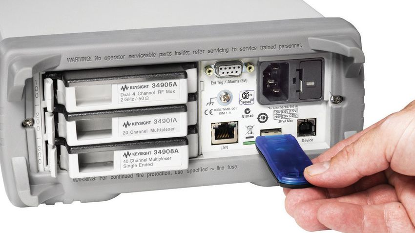
At a fraction of the cost of other standalone data acquisition systems
  –– 3-slot mainframe with built-in 6½ digit DMM
  –– 8 optional switch and control plug-in modules
  –– Measures and converts 11 different input signals: temperature with thermocouples, RTDs and thermistors; dc/ac volts; 2- and
     4-wire resistance; frequency and period; dc/ac current
  –– IO options for easy connectivity to your PC:
      –– 34970A: GPIB, RS-232
      –– 34972A: LAN, USB
  –– Graphical Web interface for point and click monitor and control (34972A)
  –– USB flash drive support to copy/log data in standalone applications (34972A)
  –– Includes BenchVue DAQ software to configure and control tests, display results and collect data for further analysis

Table of Contents
Features������������������������������������������������������������������������������������������������������������������������������������������������������������������������������������������� 3

More Power and Flexibility than You Ever Imagined You Could Afford���������������������������������������������������������������������������������������� 6

The Keysight 34970A/34972A Offers Unequaled Versatility for Your Data Acquisition Applications��������������������������������������� 7
   A powerful, flexible data acquisition system for automated test...........................................................................................10
     ATE feature checklist................................................................................................................................................................ 11
     Low-cost, high-quality switching for automated test............................................................................................................12
     Customize your Keysight 34970A/34972A with plug-in modules.........................................................................................13
     34970A and 34972A Keysight modules-at-a-glance selection guide...................................................................................13
     Keysight Quality........................................................................................................................................................................14
     Spec Interpretation Guide........................................................................................................................................................15
     34970A/34972A Accuracy Specifications ± (% of reading + % of range).............................................................................16
     Single Channel Reading Rates to I/O or Internal Memory.....................................................................................................18
     System Specifications..............................................................................................................................................................19
     Modules Specifications............................................................................................................................................................20
 Multiplexer Selection Guide.....................................................................................................................................................21
		 34901A............................................................................................................................................................................21
		 34902A............................................................................................................................................................................22
		 34908A............................................................................................................................................................................22
		 34903A ...........................................................................................................................................................................23
		 34904A ...........................................................................................................................................................................23
		 34905A 50 Ω/34906A 75 Ω ..........................................................................................................................................24
		 34907A ...........................................................................................................................................................................25
     Rack Mounting and Dimensions...............................................................................................................................................26

Ordering Information���������������������������������������������������������������������������������������������������������������������������������������������������������������������27

  Find us at www.keysight.com                                                                                                                                                                Page 2
Features
Price and performance beyond compare                                 The internal autoranging DMM directly measures 11 different
                                                                     functions, eliminating the need for expensive external signal
Go ahead and compare the Keysight Technologies, Inc. 34970A          conditioning. And our unique design allows complete per channel
and 34972A Data Acquisition/Switch Units with other data             configurability for maximum flexibility and quick, easy set up. It’s
acquisition systems currently available. You’ll find it hard to      like having an independent, high-performance DMM behind each
come up with a system that offers the powerful measurement           channel.
performance, flexibility, connectivity options and ease of use of
the 34970A/34972A—even in systems costing three to five times
as much.
                                                                     Standard connectivity to the PC
                                                                     Whether you use GPIB, RS-232, LAN or USB interfaces, the
What can you expect from a data acquisition                          34970A/34972A family offers easy connection to the PC. The
                                                                     34970A offers traditional GPIB and RS-232 interfaces. The
system that’s this affordable? Measurements you
                                                                     34972A has built-in Gigabit LAN and USB 2.0 so you can connect
can trust                                                            to a modern PC without having to purchase any GPIB cards,
We took the measurement engine from our best-selling benchtop        cables or converter boxes. With the standard LAN connections
DMM and embedded it inside a 3-slot mainframe. You get the           you also get the added benefit of a graphical Web interface for
benefit of proven Keysight measurement performance, universal        easy configuration of measurements and monitoring of results
inputs with built-in signal conditioning, and modular flexibility,   using a standard Web browser.
all in a low-cost, compact data acquisition package. The
34970A/34972A features 6½ digits (22 bits) of resolution, 0.004%     Convenient data storage with USB flash drive
basic dcV accuracy, and ultra-low reading noise. Combine that
                                                                     The 34972A also features a built-in USB memory port so that
with scan rates of up to 250 channels/sec, and you’ve got the
                                                                     you can use a USB flash drive to upload BenchLink Data Logger
speed and accuracy you need to get the job done right the first
                                                                     configurations into the 34972A and collect data without being
time.
                                                                     connected to a PC. Data can be logged directly to the USB
                                                                     flash drive, extending your instrument’s memory, or copied from
Built-in signal conditioning to get your job done                    internal memory for transfer to a computer in another location.
Whether you need to measure temperature, ac/dc volts,
resistance, frequency, or current, the 34970A/34972A can handle
it.

 Find us at www.keysight.com                                                                                                       Page 3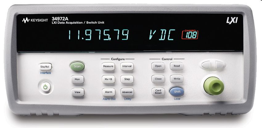
Easy to use graphical Web interface (34972A only)
The built-in graphical Web interface provides easy access and
control of the instrument using a Java-enabled Web browser
such as Internet Explorer. Using this interface you can configure
measurements, define and execute scan lists, or monitor
measurement results from anywhere on the network. Simply enter
the instrument host name or IP address into the browser URL and
gain access to the instrument’s capabilities with simple point and
click control right in your browser.
  –– Specify per channel measurement configuration
  –– Define and execute switch scans
  –– Open, close, or monitor switch positions
  –– Monitor measurement readings
  –– View and save data
  –– Send SCPI commands and view IO command log
  –– View error queue
  –– View instrument information like module configuration, relay
     counts, firmware revisions, and more
Additionally, since the Web interface is built into the instrument,
you can access it on any operating system that supports a Web
browser without having to install any special software.               BenchVue DAQ software saves you time and
                                                                      money
Password protection and LAN lock out are also provided
                                                                      Now you don’t have to spend your valuable time writing or
to limit access. The graphical Web interface makes it easy
                                                                      configuring software. Keysight BenchVue DAQ software gives
to configure measurements, set up and execute scans or
                                                                      you a familiar Microsoft Windows interface for test configuration
troubleshoot your designs from anywhere on the network.
                                                                      and real-time data display and analysis. Even better, the data
                                                                      logging application is included with every standard Keysight
                                                                      34970A/34972A.

 Find us at www.keysight.com                                                                                                      Page 4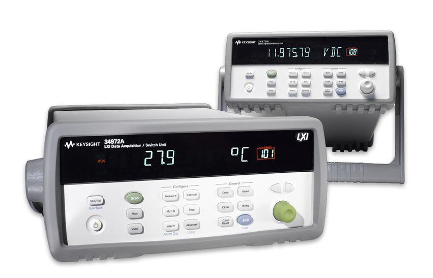
Unequaled ease of use                                              34970A and 34972A are compatible
From the simplified configuration to BenchVue DAQ, we put in       The 34972A LXI Data Acquisition/Switch Unit is an LXI version
extra time and energy so you don’t have to. Simple things like     of the 34970A. It replaces the GPIB and RS-232 interfaces with
on-module screw-terminal connectors, built-in thermocouple         modern connectivity for a direct connection to your PC or Laptop.
reference junctions, well-organized user documentation full of
examples and hints, and a standard Getting Started kit that will   The 8 plug-in modules can be used with either unit—so all the
have you making measurements in just a few minutes all add up      measurements and wiring are compatible. The 34972A can be
to increased productivity, whether you use the instrument every    easily integrated into an existing test program with a simple
day or only now and then.                                          change to the instrument address. Since the 34972A code is a
                                                                   superset of the 34970A code, once the instrument address is
Custom configurations that grow with you                           changed, the test program will run as normal.

Three module slots and eight switch/control modules allow          Example:
you to customize the 34970A/34972A to meet your unique
requirements. Buy only what you need—and add more modules          Change:
later as your application grows.                                   Set inst1.IO = ioMgr.Open(“GPIB0::9::INSTR”)

                                                                   To:
                                                                   Set inst1.IO = ioMgr.Open(“TCPIP0::156.140.77.230::inst0::
                                                                   INSTR”)

                                                                                                           34970A        34972A
                                                                    Support 8 plug-in modules                 ●                 ●

                                                                    LabView drivers                           ●                 ●

                                                                    IVI-C, IVI-COM drivers                    ●                 ●

                                                                    BenchLink Data Logger                     ●                 ●

                                                                    Optional BenchLink Data Logger Pro        ●                 ●

                                                                    Graphical Web interface                                     ●

                                                                    Gigabit LAN                                                 ●

                                                                    USB 2.0                                                     ●

                                                                    USB memory port                                             ●

                                                                    GPIB                                      ●

                                                                    RS-232                                    ●

 Find us at www.keysight.com                                                                                                        Page 5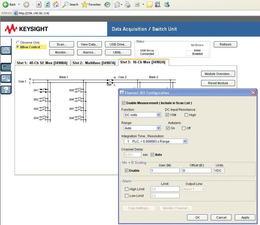
More Power and Flexibility than You Ever Imagined You Could Afford

     6½ digit (22-bit) internal DMM                Intuitive front panel with
                                                   task-oriented, self-guiding menus                      50 k readings of non-volatile memory
     measures 11 functions without
                                                                                                          holds data when power is removed
     external signal conditioning

  Monitor display
  mode lets you
  keep an eye on
  tests in progress

Scaling function for
converting raw inputs
into user-defined units

                          HI/LO alarm limits on each input                             Battery-backed real-time clock for pacing
                          channel, plus 4 TTL alarm outputs                            scans and timestamping readings

                                                                  34972A

                                                                                                                                     USB

    –– Offers up to 96 matrix
       crosspoints or                                                                                              USB memory port to log/
       120 single-ended                                                                                    transfer data to a USB flash drive
       channels
    –– 8 switch and control                                                             Built-in LAN and USB for instant connection to a PC
       plug-in modules to
       choose from
    –– Keysight BenchLink Data
       Logger 3 Keysight VEE,
                                                                 34970A
       IVI-C, IVI-COM and
       National Instruments
       LabView drivers included

                                                                                                                              GPIB

                                                                                            34970A built-in GPIB and RS-232 interfaces

Find us at www.keysight.com                                                                                                                 Page 6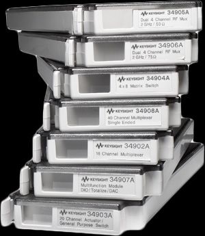
The Keysight 34970A/34972A Offers Unequaled Versatility for Your Data
Acquisition Applications
In the past, you had to make a choice. On the one hand, you could   Whether you’re an R&D engineer working on characterizing
choose the simple operation and low cost of a data logger. On the   your latest design, or a manufacturing engineer building a test
other hand, you had the flexibility and higher performance of a     system or troubleshooting a process, the 34970A/34972A Data
modular data acquisition system. The Keysight 34970A/34972A         Acquisition/Switch Unit offers the best combination of price and
Data Acquisition/Switch Unit gives you the best of both worlds:     measurement performance.
a simple user interface with low per-channel cost, modular
flexibility, standard connectivity and impressive measurement       It’s a data logger
performance.
                                                                    Configured with a 20-channel relay multiplexer, the 34970A/
                                                                    34972A becomes a powerful, low-cost data logger for simple
                                                                    characterization applications. What’s more, the 34972A with
                                                                    its LAN and USB interfaces is ideal for easy set up and control
                                                                    for data logging applications in remote locations. For more
                                                                    information on using the 34970A/34972A for data logging
                                                                    applications, see page 8.

                                                                    It’s a data acquisition front end
                                                                    The 34970A/34972A is an automated test system with excellent
                                                                    measurement performance—it’s got the accuracy, resolution, and
                                                                    speed you need. See page 10 for application information.

                                                                    It’s a switch system
                                                                    Order the mainframe without the internal DMM and you’ve got an
                                                                    even lower cost, high-quality signal routing solution. See page 12
                                                                    for details.

 Find us at www.keysight.com                                                                                                     Page 7
An Easy-to-Use Data Logger for Monitoring and Characterization Applications
Data loggers are used to monitor multiple signals (temperature, The 34972A can be set up at remote locations and accessed
voltage, etc.) over extended periods of time to identify through the Web interface on a network connection or through
irregularities. Example applications include environmental the USB port by copying instrument configurations and
chamber monitoring, component inspection, benchtop testing, measurement data results to a USB flash drive.
process troubleshooting, and temperature profiling.
Better measurements with fewer hassles
The Keysight 34970A/34972A is easy to use for a multitude of
data logging and monitoring applications, either stand-alone or Tired of putting up with the mediocre measurement performance
with a computer. Its flexible, modular design makes it scalable you get with most data loggers or plug-in data acquisition
from 20 to 120 channels, and lets you add actuator, digital I/O, boards? The 34970A/34972A offers 6½ digits of resolution and
and analog output channels for simple control. Its small size, 0.004% basic 1-year dcV accuracy.
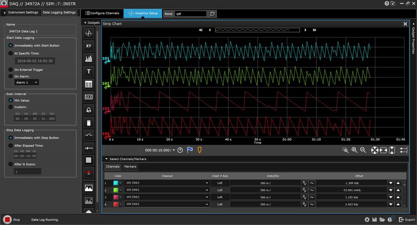
ruggedized features and USB memory port on the 34972A
make it perfect for portable applications. Use GPIB (IEEE 488)
or RS-232 interfaces in the 34970A for legacy systems or use
the 34972A with standard LAN and USB interfaces for simple
connection to the PC and support of remote applications.
Simplify Your Data Gathering with Keysight BenchVue DAQ Software
Do you want PC-based data logging capability, but don’t want A familiar spreadsheet environment makes it easy to configure
to spend hours programming? BenchVue DAQ software is the and control your tests. And a rich set of colorful graphics
answer. This Windows-based application is designed to make it a provides many options for analyzing and displaying your data—all
snap to use your PC for gathering and analyzing measurements. with point-and-click ease. Set up multiple graphics using strip
Use it to set up your test, acquire and archive measurement charts, histograms, bar and scatter charts, individual channel
data, and perform real-time display and analysis of the incoming results, and more. And of course you can use BenchVue DAQ to
measurements. easily move data to other applications for further analysis, or for
inclusion in your presentations and reports.
Find us at www.keysight.com Page 8And the 34970A/34972A measures and converts 11 different Monitor any input
input signals:
A special display mode monitors a selected input channel,
–– Temperature with thermocouples, RTDs, and thermistors continuously updating the display with new readings—even
–– dc and ac volts during a scan. Or, when using the 34972A with built-in LAN, the
–– 2- and 4-wire resistance channels can be monitored over the network using the graphical
–– Frequency and period Web interface. It’s great for keeping an eye on a key input, or for
–– dc and ac current troubleshooting your system before a test.
What’s more, each channel is independently configurable. This Non-volatile memory and USB flash drive adds
means you can configure channel 1—for dcV, channel 2 for a convenience, portability
K-type thermocouple, and channels 3 and 13 for a 4-wire RTD
measurement—all on the same module, all in a single scan. For All readings are automatically time-stamped and stored in a
custom linear conversions, use the Mx+B scaling function on any nonvolatile 50,000 reading memory—enough memory to hold
channel. You can even display a custom 3-character engineering more than a week’s worth of data (20 channels scanned every
label like RPM or PSI to identify your measurement units. five minutes). The nonvolatile memory holds your data even after
power is removed, so you can use the 34970A/34972A to collect
data at a remote location for later uploading to a PC. Or if you
Versatile alarms need even more memory, the 34972A’s USB port can be used to
Alarms are available on a per-channel basis as well. Enter a high log data directly to a USB flash drive or to copy the data from the
limit, a low limit, or both. The 34970A/34972A compares each reading memory without being connected to a computer.
reading to its limits and flags any out-of-range measurements.
You can assign one of four TTL alarm outputs to any input
channel to trigger external alarm lights, sirens, or send a TTL
pulse to your control system, all without a PC connected. Data logging feature checklist
–– From 1 to 120 channels of analog input
Scanning made simple –– Measurements include dc volts, ac volts,
The 34970A/34972A automatically builds a scan list that thermo-couple, thermistor and RTD temperature
includes all configured inputs (even digital inputs from the measurements, 2- and 4-wire Ohms, dc current, ac
Keysight 34907A multifunction module) in ascending order current, frequency, and period
by channel number. You can pace scans by setting the –– 6½ digits (22 bits) of resolution with 0.004% basic
34970A/34972A ’s internal timer for automatic scanning at a 1-year dcV accuracy
specific interval, by manually pressing a front-panel button, or by –– 50 k reading nonvolatile memory including
sending a software command or external TTL trigger pulse. time-stamp
–– Scaling and alarms available on each channel
–– Full-featured front panel for stand-alone
configuration, troubleshooting, and data viewing
–– BenchVue DAQ software for configuration and data
analysis
–– Nonvolatile storage for five complete instrument
states
–– Built-in LAN or USB interfaces to support remote
data logging applications (34972A only)
Find us at www.keysight.com Page 9A powerful, flexible data acquisition system for Flexible functionality
automated test The DMM is installed inside the chassis rather than in one of the
The 34970A/34972A gives you the resolution, accuracy, slots, leaving all three mainframe slots free for switch and control
repeatability, and speed you’ve come to expect from a Keysight modules. You can choose from eight different modules (see page
data acquisition system. It provides the measurement muscle 13) to get the precise functionality you need now—while giving you
you need, along with signal routing and control capability, in a flexibility for future expansion.
flexible, modular format that can grow and change to match your
varied applications. The internal DMM gives you the flexibility to measure 11 types of
inputs easily and inexpensively. The built-in signal conditioning and
conversion routines turn raw inputs directly into real information.
Powerful measurements Each measurement channel is independently configurable, so you
The internal 6½ digit DMM brings the power and performance can set different measurement functions, scale factors and alarm
of a world-class stand-alone DMM to the 34970A/34972A, but limits, even on adjacent channels. Advanced measurement features
at a fraction of the cost and in a fraction of the space. It’s as such as offset compensation, variable integration time, and delay
accurate as the best bench DMM available: 0.004% basic 1-year are also selectable on a per-channel basis.
dcV accuracy, 0.06% basic 1-year acV accuracy, and 0.01% basic
1-year resistance accuracy. Our patented Multi-slope III A-D
technology offers incredible linearity (2 ppm of reading +1 ppm
of range) along with 22 bits of real resolution. And since it is an
integrating A/D, it provides excellent noise rejection as well—a
Get better measurements with built-in
nice change from noisy PC plug-ins and sampling A/Ds. No more signal conditioning
averaging lots of samples just to see the real data you wanted. The Keysight 34970A/34972A architecture offers
And if you need high scan rates, the 34970A/34972A is capable advantages over other data acquisition solutions which
of delivering fully converted measurements at speeds up to rely on external or plug-in signal conditioning modules for
250 ch/s. handling functions other than dcV:
The input section of the DMM is optically isolated and shielded –– Minimizes external wiring and the resultant potential
from the 34970A/34972A’s earth-referenced circuitry and for noise and errors to enter your system
computer interface, offering up to 300 V of input isolation. This is –– Reduces hidden costs and overall system cost by
important for reducing ground loop and common mode voltage avoiding unnecessary cables, breakout boxes and
errors associated with long wiring runs and floating measurement signal conditioning elements
sources. –– Simplifies your configuration—for faster, easier
setup—with fewer connections and components
–– Takes the guesswork out of error analysis.
–– Measurement accuracies are specified to include all
system-related errors
–– Improves reliability, with fewer interconnects and
fewer parts that can fail
Find us at www.keysight.com Page 10Software drivers
Your months of test system software development time need not ATE feature checklist
go to waste. Software drivers that support (C, C#, Visual Basic, –– 3-slot cardcage with 6½ digit (22 bit) internal DMM
Visual Studio), Keysight VEE and National Instruments LabView 0.004% basic 1-year dcV accuracy; 0.06% acV
are available for the 34970A/34972A to make integration into accuracy
your test system easy. Standard RS-232 and GPIB interfaces –– Up to 120 single-ended measurements or 96 matrix
on the 34970A or LAN and USB on the 34972A and SCPI crosspoints in a 3½” high, half-rack instrument
programming language make integration even easier. –– Eight switch and control modules include low-
frequency and RF multiplexers, matrix and actuation
switches, digital input and output, analog output, and
event recording
–– Scan rates up to 250 ch/s
–– GPIB and 115 kbaud RS-232 interfaces standard
(34970A)
–– Graphical Web interface to speed up test
development and monitor tests remotely (34972A)
–– Software drivers available to support Keysight VEE
–– and National Instruments LabView
–– Relay maintenance feature for system maintenance
Compact 60-channel data acquisition system
Find us at www.keysight.com Page 11Low-cost, high-quality switching for automated Easy scanning
test The 34970A/34972A can easily scan with external instruments.
If you don’t need the built-in measurement capability of the It builds a scan list that includes all enabled low frequency
34970A/34972A, save money by ordering it without the DMM. multiplexer inputs. Scans are controlled with the external channel
What you end up with is the lowest cost switch unit on the advance input, or with the front panel Step key.
market. It’s an ideal solution for routing test signals to and from
your DUT and assorted instruments, including external DMMs, Connect to the company network
scopes, counters, and power supplies. Plus, you can add the
With the 34972A’s LAN interface, the instrument is easily
DMM later if your needs change.
connected to the company network to collect measurement data
to a central database, remotely access the instrument’s set up, or
The functionality you need monitor measurement data from anywhere on the network.
We put a lot of thought into defining and designing the modules
for the 34970A/34972A in order to cover a broad spectrum of
switching and signal routing requirements with fewer modules.
The result? Simplified ordering and easier configuration. And
while we were at it, we improved performance and density. The
34970A/34972A modules can switch from microvolts to 300
volts, dc to 2 GHz, and with densities as high as 120 single-ended
channels or 96 matrix crosspoints per frame. Plus, simple control
capabilities like analog outputs, open collector digital outputs,
and isolated Form-C relays for controlling higher-powered
devices are available.
Low-cost switching system for automated testing
Find us at www.keysight.com Page 12Customize your Keysight 34970A/34972A with More channels in less space
plug-in modules Surface mount construction and a highly integrated design
A complete selection of plug-in modules gives you high quality minimize the space required for relay drive and interface circuitry.
measurement, switching, and control capabilities to choose High density on-module connectors save both board and
from. Modules include both low-frequency and RF multiplexers, connector space normally required by a terminal block. We use
a matrix switch, a general-purpose switch, and a multifunction the latest technology to squeeze the most out of the remaining
module that includes digital input/output, analog output, and board space, giving you up to 40 single-ended channels in
totalizer capabilities. You can mix and match modules to get just roughly the same space used by many data acquisition system
the functionality you need right now—then change or add more terminal blocks.
channels later as your application grows.
Convenient connections
Modules for the 34970A/34972A are designed to make your
On-module screw-terminal connectors make wiring more
testing easier, faster, and more reliable. Here’s how:
convenient. Built-in strain relief cable routing and cable tie
points keep your wiring secure and safe from accidental tugs and
Higher throughput pulls. An internal analog bus routes signals from any of the low
Our unique architecture incorporates a high-performance frequency multiplexers directly to the internal DMM, without the
microprocessor on each module, off loading the mainframe need for external connections.
processor and minimizing backplane communications for faster
throughput. Use the chart below to help you pinpoint the modules that meet
your needs.
34970A and 34972A Keysight modules-at-a-glance selection guide
Model description Type Speed Max Max Bandwidth Thermal Comments Page
(ch/sec) volts amps offset
34901A 2-wire armature 60 300 V 1A 10 MHz < 3 µV Built-in cold junction reference 21
20 ch Multiplexer (4-wire selectable) 2 additional current channels
+ 2 current channels (22 total)
34902A 2-wire reed 250 1 300 V 50 mA 10 MHz < 6 µV Built-in cold junction reference 21
16 ch Multiplexer (4-wire selectable)
34903A SPDT/form C 120 300 V 1A 10 MHz < 3 µV 23
20 ch Actuator/GP
Switch
34904A 4 x 8 Matrix 2-wire armature 120 300 V 1A 10 MHz < 3 µV 23
34905A Common low 60 42 V 0.7 A 2 GHz < 6 µV 1 GHz bandwidth through 24
Dual 4 ch RF Mux 50 Ω (unterminated) BNC-to-SMB adapter cable
34906A Common low 60 42 V 0.7 A 2 GHz < 6 µV 1 GHz bandwidth through 24
Dual 4 ch RF Mux 75 Ω (unterminated) BNC-to-SMB adapter cable
34907A Two 8-bit digital I/O ports 42 V 400 mA Open drain 25
Multifunction Module 26-bit event counter 42 V 100 KHz Selectable input threshold
Two 16-bit analog outputs ± 12 V 10 mA dc Max 40 mA total output per frame
34908A 1-wire armature 60 300 V 1A 10 MHz < 3 µV Built-in cold junction reference 21
40 ch Single-Ended (common low) No four-wire measurements
Mux
1. Up to 250 ch/sec to internal memory. See scanning rates for measurement condition and rate on each instrument.
Find us at www.keysight.com Page 13Keysight quality Take the guesswork out of relay maintenance
We know you can’t afford instrument downtime due to hardware The 34970A/34972A uses our proprietary relay maintenance
failures and unscheduled maintenance. That’s why our engineers system to help you to predict relay end-of-life and avoid
designed reliability into the 34970A/34972A: A rugged enclosure, costly production line downtime. It automatically counts every
state-of-the-art surface mount construction throughout, reduced individual switch closure and stores it in nonvolatile memory on
parts counts, and rigorous and thorough testing on all aspects of each module. You can query the total number of cycles on any
the product. individual channel so you can schedule maintenance and avoid
erratic end-of-life failures.
Find us at www.keysight.com Page 14Spec interpretation guide Now, multiply the 10 V temperature coefficient from the following
page by the number of degrees outside of operating range for
The following pages list the technical specifications for the additional error:
Keysight 34970A/34972A Data Acquisition/Switch Unit and its
modules. The explanations and examples below are helpful in (0.0005% reading + 0.0001% range)
understanding how to interpret these specifications: –– /°C x (35 - 28 °C) =
–– Measurement accuracy is specified as percent of reading plus (0.0005% reading + 0.0001% range)
percent of range, where reading is the actual measured value –– /°C x 7 °C =
and range is the name of the scale (1 V, 10 V, etc.)—not the
full scale value (1.2 V, 12 V, etc.). 0.0035% reading + 0.0007% range = 385 µV
–– DMM measurement accuracies include all switching errors. –– Total error is then:
Switching errors are also listed separately in the module –– 365 µV + 385 µV = 750 µV or 0.008%
specifications section. Temperature measurement accuracies
include ITS-90 conversion errors. The thermocouple
accuracies include the reference junction error as well.
Example 3: Thermocouple measurement accuracy
–– Accuracies are listed as either 24-hour, 90-day, or 1-year Calculating the total thermocouple reading error is easy with
specifications. This refers to the length of time since the the 34970A/34972A—just add the listed measurement accuracy
instrument’s last calibration. Use the specification that to the accuracy of your transducer. Switching, conversion,
matches your calibration cycle. The 24-hour specifications and reference junction errors are already included in the
are useful for determining short-term relative performance. measurement specification. For this example, assume a J-type
thermocouple input reading 150 °C.
Example 1: Basic dcV accuracy
From the following page, total error is:
Calculate the accuracy of the following measurement: –– Thermocouple probe accuracy + 1.0 °C
–– 9 V dc input The probe vendor specifies accuracy of 1.1 °C
–– 10 V dc range –– or 0.4%, whichever is greater.
–– 1-year accuracy specifications
–– Normal operating temperature (18 - 28 °C) Total error is then:
–– 1.0 ºC + 1.1 °C = 2.1 °C total, or 1.4%
From the following page, the 1-year accuracy is:
–– 0.0035% of reading + 0.0005% of range
Example 4: acV accuracy
Which translates into: The acV function measures the true RMS value of the input
–– (0.0035/100 x 9 V)+ (0.0005/100 x 10 V) = 365 µV waveform, regardless of waveshape. Listed accuracies assume a
sinewave input. To adjust accuracies for non-sinusoids, use the
For a total accuracy of: listed crest factor adder.
–– 365 µV/9 V = 0.0041%
For this example, assume a ± 1 V square wave input with
Example 2: Extreme operating temperature 50% duty cycle and a 1 kHz frequency.
When the 34970A/34972A is used outside of its 18 - 28 °C Accuracy for 1 V, 1 kHz sinusoid is:
temperature range, there are additional temperature drift errors –– 0.06% reading + 0.04% range
to consider. Assume the same conditions in Example 1, but at a
35°C operating temperature. A 50% duty cycle squarewave has a crest factor of
–– Peak value / RMS value = 1 V / 1 V = 1
The basic accuracy is again:
–– 0.0035% of reading + 0.0005% of range = 365 µV From crest factor table, add:
–– 0.05% of reading
The total accuracy is:
–– 0.11% of reading + 0.04% of range = 1.5 mV or 0.15%
Find us at www.keysight.com Page 1534970A/34972A accuracy specifications ± (% of reading + % of range) 1
Includes measurement error, switching error, and transducer conversion error
Range 3 Frequency, etc. 24 hour 2 90 Day 1 Year Temperature coefficient
23 ± 1 °C 23 ± 5 °C 23 ± 5 °C 0 – 18 °C, 28 - 55 °C
DC voltage
100.0000 mV 0.0030 + 0.0035 0.0040 + 0.0040 0.0050 + 0.0040 0.0005 + 0.0005
1.000000 V 0.0020 + 0.0006 0.0030 + 0.0007 0.0040 + 0.0007 0.0005 + 0.0001
10.00000 V 0.0015 + 0.0004 0.0020 + 0.0005 0.0035 + 0.0005 0.0005 + 0.0001
100.0000 V 0.0020 + 0.0006 0.0035 + 0.0006 0.0045 + 0.0006 0.0005 + 0.0001
300.000 V 0.0020 + 0.0020 0.0035 + 0.0030 0.0045 + 0.0030 0.0005 + 0.0003
True RMS AC voltage 4
All ranges from 100.0000 3 Hz – 5 Hz 1.00 + 0.03 1.00 + 0.04 1.00 + 0.04 0.100 + 0.004
mV to 100.0000 V 5 Hz – 10 Hz 0.35 + 0.03 0.35 + 0.04 0.35 + 0.04 0.035 + 0.004
10 Hz – 20 kHz 0.04 + 0.03 0.05 + 0.04 0.06 + 0.04 0.005 + 0.004
20 kHz – 50 kHz 0.10 + 0.05 0.11 + 0.05 0.12 + 0.05 0.011 + 0.005
50 kHz – 100 kHz 0.55 + 0.08 0.60 + 0.08 0.60 + 0.08 0.060 + 0.008
100 kHz – 300 kHz 5 4.00 + 0.50 4.00 + 0.50 4.00 + 0.50 0.20 + 0.02
300.0000 V 3 Hz – 5 Hz 1.00 + 0.05 1.00 + 0.08 1.00 + 0.08 0.100 + 0.008
5 Hz – 10 Hz 0.35 + 0.05 0.35 + 0.08 0.35 + 0.08 0.035 + 0.008
10 Hz – 20 kHz 0.04 + 0.05 0.05 + 0.08 0.06 + 0.08 0.005 + 0.008
20 kHz – 50 kHz 0.10 + 0.10 0.11 + 0.12 0.12 + 0.12 0.011 + 0.012
50 kHz – 100 kHz 0.55 + 0.20 0.60 + 0.20 0.60 + 0.20 0.060 + 0.020
100 kHz – 300 kHz 5 4.00 + 1.25 4.00 + 1.25 4.00 + 1.25 0.20 + 0.05
Resistance 6
100.0000 Ω 1 mA current source 0.0030 + 0.0035 0.008 + 0.004 0.010 + 0.004 0.0006 + 0.0005
1.000000 kΩ 1 mA 0.0020 + 0.0006 0.008 + 0.001 0.010 + 0.001 0.0006 + 0.0001
10.00000 kΩ 100 µA 0.0020 + 0.0005 0.008 + 0.001 0.010 + 0.001 0.0006 + 0.0001
100.0000 kΩ 10 µA 0.0020 + 0.0005 0.008 + 0.001 0.010 + 0.001 0.0006 + 0.0001
1.000000 MΩ 5.0 µA 0.002 + 0.001 0.008 + 0.001 0.010 + 0.001 0.0010 + 0.0002
10.00000 MΩ 500 nA 0.015 + 0.001 0.020 + 0.001 0.040 + 0.001 0.0030 + 0.0004
100.0000 MΩ 500 nA || 10 MΩ 0.300 + 0.010 0.800 + 0.010 0.800 + 0.010 0.1500 + 0.0002
Frequency and period 7
100 mV to 300V 3 Hz – 5 Hz 0.10 0.10 0.10 0.005
5 Hz – 10 Hz 0.05 0.05 0.05 0.005
10 Hz – 40 Hz 0.03 0.03 0.03 0.001
40 Hz – 300 kHz 0.006 0.01 0.01 0.001
DC current (34901A only)
10.00000 mA < 0.1 V burden 0.005 + 0.010 0.030 + 0.020 0.050 + 0.020 0.002 + 0.0020
100.0000 mA < 0.6 V 0.010 + 0.004 0.030 + 0.005 0.050 + 0.005 0.002 + 0.0005
1.000000 A 100 mV. For 10 mV to 100 mV inputs multiply % of reading error x 10.
current ranges. 8. Specified only for inputs > 10 mA.
4. For sinewave input > 5% of range. For inputs from 1% to 5% of range and < 50 kHz, 9. For total measurement accuracy, add temperature probe error.
add 0.1% of range additional error. 10. Thermocouple specifications not guaranteed when 34907A module is present. For
5. Typically 30% of reading error at 1 MHz, limited to 1 x 10⁸ V Hz. < 1 °C accuracy, a precision external reference is required.
Find us at www.keysight.com Page 16Measurement characteristics 7
Measurement noise rejection 60 (50) Hz 1
DC voltage dc CMRR 140 dB
Measurement Method Continuously Integrating ac CMRR 70 dB
Multi-slope III A-D converter Integration time Normal mode rejection 2
A/D linearity 0.0002% of reading + 0.0001 % of range 200 plc/3.33s (4s) 110 dB 3
Input resistance 100 plc/1.67s (2s) 105 dB 3
100 mV, 1 V, 10 V ranges Selectable 10 MΩ or > 10,000 MΩ 20 plc/333 ms (400 ms) 100 dB 3
100 V, 300 V ranges 10 MΩ ± 1% 10 plc/167 ms (200 ms) 95 dB 3
Input bias current < 30 pA at 25 °C 2 plc/33.3 ms (40 ms) 90 dB
Input protection 300 V all ranges 1 plc/16.7 ms (20 ms) 60 dB
< 1 plc 0 dB
True RMS AC voltage
Measurement method AC coupled True RMS — measures the AC
component of the input with up to 300 Vdc of
bias on any range Operating characteristics 4
Crest factor Maximum of 5:1 at Full Scale
Additional crest factor
errors (non-sinewave) Crest Factor 1-2 0.05 % of reading Single channel measurement rates 5
Crest Factor 2-3 0.15 % of reading Function Resolution 8 34970A/34972A
Crest Factor 3-4 0.30 % of reading
Crest Factor 4-5 0.40 % of reading readings/sec
Input impedance 1 MΩ ± 2% in parallel with 150 pF dcV, 2-wire resistance 6½ digits (10 plc) 6 (5)
Input protection 300 Vrms all ranges 5½ digits (1 plc) 54 (47)
4½ digits (0.02 plc) 500
Resistance
Measurement method Selectable 4-wire or 2-wire Ohms Thermocouple 0.1 °C (10 plc) 6 (5)
Current source referenced to LO input 0.1 °C (1 plc) 52 (47)
Offset compensation Selectable on 100 Ω, 1 kΩ, 10 kΩ ranges (0.02 plc) 280
Maximum lead resistance 10% of range per lead for 100 Ω and 1 kΩ RTD, thermistor 0.01 °C (10 plc) 6 (5)
ranges. 1 kΩ on all other ranges
Input protection 300 V on all ranges 0.1 °C (1 plc) 49 (47)
1 °C (0.02 plc) 200
Frequency and period acV 6½ Slow (3 Hz) 0.14
Measurement method Reciprocal counting technique 6½ Med (20 Hz) 1
Voltage ranges Same as AC Voltage function
Gate time 1 s, 100 ms, or 10 ms 6½ Fast (200 Hz) 8
Measurement timeout Selectable 3 Hz, 20 Hz, 200 Hz LF limit 6½ 6 100
Frequency, period 6½ digits (1 s gate) 1
DC current 5½ digits (100 ms) 9
Shunt resistance 5Ω for 10 mA, 100 mA; 0.1 Ω for 1 A
Input protection 1 A 250 V fuse on 34901A module 4½ digits (10 ms) 70
True RMS AC current
Measurement method Direct coupled to the fuse and shunt.
AC coupled True RMS measurement (measures
the ac component only)
Shunt resistance 5 Ω for 10 mA; 0.1 Ω for 100 mA, 1 A
Input protection 1 A 250 V fuse on 34901A module
Thermocouple
Conversion ITS-90 software compensation
Reference junction type Internal, Fixed, or External
Open thermocouple check Selectable per channel. Open > 5 kΩ
Thermistor 44004, 44007, 44006 series
1. For 1 KΩ unbalance in LO lead.
RTD α = 0.00385 (DIN) and α = 0.00391 2. For power line frequency ± 0.1%.
3. For power line frequency ± 1% use 80 dB or ± 3% use 60 dB.
4. Reading speeds for 60 Hz and (50 Hz) operation.
5. For fixed function and range, readings to memory, scaling and alarms off,
AZERO OFF, USB datalogging OFF.
6. Maximum limit with de fault settling delays defeated.
7. Isolation voltage (ch-ch, ch-earth) 300 Vdc, ac rms.
8. 6½ digits = 22 bits, 5½ digits = 18 bits, 4½ digits = 15 bits.
Find us at www.keysight.com Page 17Single channel reading rates to I/O or internal memory
(See footnotes for conditions below) 34970A 34972A
Into memory To GPIB or RS232 To LAN, USB or memory
readings/sec readings/sec readings/sec
Single channel ASCII readings 500 440 500
Single channel while changing scale 25 25 25
(eg MEAS dcV 10/MEAS dcV 1)
Single channel while changing function 12 12 12
(eg MEAS dcV/MEAS Ohms)
Scanning measurement rates to I/O or internal memory
(See footnotes for conditions below) 34970A 34972A
Into memory To GPIB or RS232 To LAN, USB or memory
ch/sec ch/sec ch/sec
Scanning dcV or ohms channels
34901A/34908A 60 60 60
34902A 250 210 240
34902A into and out of memory (using INIT, FETCh) — 180 240
34902A with timestamp (using MEAS) — 150 240
34902A with scaling and alarms 220 190 220
34902A dcV and ohms on alternate channels 80 80 80
Scanning acV channels 2
34901A/34908A 50 50 50
34902A 100 90 100
Scanning temperature – thermistor or TC channels
34901A/34908A 50 50 50
34902A 160 150 150
Scanning digital in/totalizer channels
34907A Digital Input 275 250 275
34907A Totalizer 240 210 240
Data out of memory 3, 4
(FETCh of 50K readings)
(See footnotes for conditions below) 34970A 34972A
Single channel 1, 2 Over GPIB Over RS232 Over USB Over LAN or memory
readings/sec readings/sec readings/sec readings/sec
Readings 800 600 55 K 120 K
Readings with timestamp 450 320 35 K 60 K
1. Speeds are for 4 1/2 digits, delay 0, display off, USB data logging off, autozero off, auto-ranging off unless otherwise noted. Use MEAS command for best
I/O performance. RS232 at 115 Kbaud.
2. Maximum, with default delays defeated.
3. Assumes relative time format (time since start of scan).
4. Typical rates assuming lightly loaded PC and limited other traffic on I/Os. LAN rates assume use of socket connection; VXI11 will be less.
5. For fixed function and range, readings to memory, scaling/alarms/autozero off.
Find us at www.keysight.com Page 18System Specifications
Scanning inputs General specifications
Analog 34901A, 34902A, and 34908A multiplexer channels Power supply 100 V/120 V/220 V/240 V ± 10%
Digital 34907A digital in and totalize Power line frequency 45 Hz to 66 Hz automatically sensed
Scan list Scans channels in ascending order Power consumption 12 W (25 VA peak)
Operating environment Full accuracy for 0 to 55 °C
Scan triggering Full accuracy to 80% RH at 40 °C
Source Interval, external, button press, software, or on (non condensing)
monitor channel alarm Full accuracy to 40% RH for 41 °C to 55 °C
Scan count 1 to 50,000 or continuous (non-condensing)
Scan interval 0 to 99 hours; 1 ms step size Storage environment –40 to 70 °C 1
Channel delay 0 to 60 seconds per channel; 1 ms step size External Weight Net: 3.6 kg (8.0 lbs)
trig delay < 300 µs. With monitor on < 200 ms Safety Conforms to CSA, UL-1244, IEC 1010 Cat I
External trig jitter < 2 ms RFI and ESD CISPR 11, IEC 801-2/3/5/6
Alarms
Analog inputs Hi, Lo, or Hi + Lo evaluated each scan Software
Digital inputs 34907A digital in maskable pattern match or state
change Keysight BenchVue DAQ
(Now included)
34907A totalize: Hi limit only
Computer interfaces 3
Monitor channel Alarm evaluated each reading 34970A
Alarm outputs 4 TTL compatible GPIB Keysight and National Instruments PCI-GPIB
Selectable TTL logic Hi or Lo on fail RS-232 (Serial port) PC COM 1-4
Latency 5 ms (typical) 34972A
LAN 10/100/1000 BaseT
USB USB 2.0
Memory
Battery 34970A, 4-year typical life 1, Instrument driver support for programming languages
34972A User replaceable battery. IVI-C or IVI-COM driver Compatible with Windows 7, Vista SP1,
Recommend replacement once a year during CAL. XP SP2 (32-bit) IO Libraries 14.1 or greater.
Supports Keysight VEE, Visual Basic, C/C#,
Readings 50,000 internal readings with timestp
Visual Studio, National Instruments
Readable during scan LabWindows CVI and LabVIEW
States 5 instrument states with user label LabVIEW driver (VI) LabVIEW 7.0 or greater
Alarm queue Up to 20 events with channel number, reading, and Controller Recommend 800 MHz or greater,
timestamp minimum 600 MHz.
USB flash drive Support FAT or FAT 32 format
System features
Per-channel math Individual Mx + B scaling and
Min/Max/Average calculated real time
Power fail recovery Resumes scanning automatically
Relay maintenance Counts each relay closure and stores on module
User resettable
Real-time clock Battery-backed, 4-year typical life 1
1. Storage at temperatures above 40 °C will decrease battery life.
2. Software provided on CD-ROM.
3. Interface and driver must be purchased and installed separately.
4. Requires VISA command library for IEEE-488.
Find us at www.keysight.com Page 19Modules Characteristics
The Keysight 34970A/34972A accuracy specifications already On-module screw terminals accept wire sizes from 16 gage to
include the switching offset and reference junction errors shown 22 gage. Twenty-gage wire is recommended for high channel
below. These errors are listed separately for determining system count applications. The 34905A and 34906A RF Multiplexers use
error with external measurement devices. SMB connectors. A standard set of (10) BNC-to-SMB adapter
cables is provided with each RF module for convenient BNC
Up to three modules, in any combination, can be inserted connections.
into a single mainframe. The 34970A/34972A’s internal DMM
connections are accessible only through the 34901A, 34902A,
and 34908A low-frequency multiplexers.
Multiplexer Actuator Matrix RF multiplexer Multifunction
34901A 34902A 1 34908A 34903A 34904A 34905A 34906A 34907A
General
Number of channels 20 + 2 16 40 20 4x8 Dual 1 x 4 See page 25
2/4 wire 2/4 wire 1 wire SPDT 2 wire 50 Ω 75 Ω for module
specifications
Connects to internal DMM ● ● ●
Scanning speed 60 ch/s 250 ch/s 1 60 ch/s
Open/close speed 120/s 120/s 70/s 120/s 120/s 60/s
Characteristics – typical: Input
Voltage (dc , ac rms) 2 300 V 300 V 300 V 300 V 300 V 42 V
Current (dc , ac rms) 1A 50 mA 1A 1A 1A 0.7 A
Power (W , VA) 50 W 2W 50 W 50 W 50 W 20 W
Characteristics – typical: DC
Offset voltage 3 < 3 uV < 6 uV < 3 uV < 3 uV < 3 uV < 6 uV
Initial closed channel R 3 10 GΩ > 10 GΩ > 1 GΩ
Characteristics – typical: AC
Bandwidth 4 10 MHz 10 MHz 10 MHz 10 MHz 10 MHz 2 GHz 5 2 GHz 5
Insertion loss (dB) 10 MHz — — — — — –0.1 –0.1
100 MHz — — — — — –0.4 –0.4
500 MHz — — — — — –0.6 –0.5
1 GHz — — — — — –1 –1
1.5 GHz — — — — — –1.2 –1.5
2 GHz — — — — — –3 –2
SWR 0-9.99 MHz — — — — — 1.02 1.02
10-99.99 MHz — — — — — 1.05 1.05
100-499.99 MHz — — — — — 1.20 1.25
500-999.99 MHz — — — — — 1.20 1.40
1-1.499 GHz — — — — — 1.30 1.40
1.5-2 GHz — — — — — 1.40 2.00
ch-ch cross talk (dB) 4 10 MHz –45 –45 –18 6 –45 –33 –100 –85
100 MHz — — — — — –85 –75
500 MHz — — — — — –65 –65
1 GHz — — — — — –55 –50
1.5 GHz — — — — — –45 –40
2 GHz — — — — — –35 –35
Risetime < 300 ps
Signal delay < 3 ns
Capacitance HI - LO < 50 pF < 50 pF < 50 pF < 10 pF < 50 pF < 20 pF
LO - Earth < 80 pF < 80 pF < 80 pF < 80 pF < 80 pF —
Volt-Hertz limit 10 8 10 8 10 8 10 8 10 8 1010
Characteristics – typical: Other
T/C cold junction accuracy 3
0.8 °C 0.8 °C 0.8 °C 7
Switch life No load 100 M 100 M 100 M 100 M 100 M 5M 5M
Rated load 100 k 100 k 100 k 100 k 100 k 100 k 100 k
Temperature Operating All cards: 0 to 55 °C
Storage All cards: –20 to 70 °C
Humidity (non-condensing) All cards: 40°C to 80% RH
1. Not recommended for connection to ac line without external transient suppression. Up to 4. 50 Ω source, 50 Ω load.
250 ch/s to internal memory. See scanning rates for measurement condition and rate on 5. Bandwidth direct to card SMB connectors.
each instrument. 6. Isolation within channel 1 to 20 or 21 to 40 banks is –40 dB.
2. Channel-to-channel or channel-to-earth. 7. Thermocouple measurements not recommended with 34908A module due to common lo
3. Errors included in DMM measurement accuracy specifications. configuration.
Find us at www.keysight.com Page 20Multiplexer selection guide 34901A 34902A 34908A
Number of channels 20 + 2 16 40
Choose between the broad functionality of the 34901A, the high
Max scan speed 60 ch/s 250 ch/s 60 ch/s
speed scanning of the 34902A, or the single-ended density of the
34908A. These three modules are the only way to connect to the Number of contacts 2 or 4 2 or 4 1
34970A/34972A internal DMM. They can be used to scan with Temperature
external instruments as well. Thermocouple ● ● ●
2-wire RTD ● ● ●
All multiplexer modules employ break-before-make scanning, 4-wire RTD ● ●
ensuring only one closed channel (or channel pair) at a time. Thermistor ● ● ●
Multiple channel closures are allowed on the 34901A and 34902A dc Volts ● ● ●
modules when not configured for scanning. ac Volts ● ● ●
2-wire Ohms ● ● ●
The 34908A does not allow multiple channel closures at any time. 4-wire Ohms ● ●
Frequency ● ● ●
34901A Period ● ● ●
dc current ●
20-Channel General Purpose Multiplexer ac current ●
–– 60 ch/s scanning
–– Two- and four-wire scanning
–– Built-in thermocouple reference junction
–– 300 V switching
Backplane switches Channel switches
The Keysight 34901A is the most versatile H
H
multiplexer for general purpose scanning. L 01
L
It combines dense, multifunction Internal
switching with 60-channel/second scan DMM input H 10
rates to address a broad spectrum of data L
H
acquisition applications. Com
L
Two- and four-wire channels can be mixed T Bank switch
on the same module. Two additional fused H
Reference L
Com
inputs (22 channels total) route up to 1 A junction (4W sense)
H
of current to the internal DMM, allowing sensor 11
L
ac and dc current measurements without
H
the need for external shunt resistors. H
L
L
20
Internal
DMM input
(4W sense) Shunt switches
Fuse
I
L
21
I
Current
L
channels
Internal Fuse
I
DMM input 22
L
(Current)
I Com
L (Current)
Find us at www.keysight.com Page 2134902A
Backplane switches Channel switches
16-Channel High-Speed Multiplexer H
H
L 01
–– Scanning up to 250 ch/s L
Internal
–– Two- and four-wire scanning DMM input H
08
–– Built-in thermocouple reference junction L
H
L Com
The Keysight 34902A employs reed relays to
achieve scan rates up to 250 channels per second.
T Bank switch
Use this module for high-throughput automated Reference
H Com
junction
L (4W sense)
test applications as well as high-speed data H
sensor 09
logging and monitoring tasks. L
H
H
Sixteen two-wire inputs switch up to 300 V. L
L
16
Internal
Two- and four-wire channels may be mixed on the DMM input
same module. User provided shunt resistors are (4W sense)
required for current measurements.
Note: Not recommended for connection to ac line without external
transient suppression.
34908A
Channel switches
40-Channel Single-Ended Multiplexer H 01
–– 60 ch/s scanning
–– Single-wire switching for common low H 20
applications
–– Built-in thermocouple reference junction H Com
Backplane
switch L Com
H
Use the Keysight 34908A for the greatest density Bank switch
L
in common low applications, such as battery
Internal
test, component characterization, and benchtop DMM input
testing. H 21
Each module switches 40 one-wire inputs. All two-
wire internal measurements except current are H 40
T
supported. The module low connection is isolated
from earth and can float up to 300 V. Reference
junction
sensor
Note: Thermocouples must be electrically isolated from each other
to avoid current loops and subsequent measurement errors.
Find us at www.keysight.com Page 2234903A
NC
20-Channel Actuator/General Purpose Switch COM 01
NO
–– SPDT (Form C) latching relays
–– 300 V, 1 A actuation and control
This general purpose switch module has 20 independent NC
single-pole, double-throw (SPDT) relays. Use it to cycle power COM 20
to products under test, control indicator and status lights, and NO
to actuate external power relays and solenoids. Combine it with
matrix and multiplexer modules to build custom switch systems.
Its 300 V, 1 A contacts can handle up to 50 W, enough for many
power line switching applications.
34904A
Col 1 Col 2 Col 8
4x8 Two-wire Matrix Switch H L H L H L
–– 32 two-wire crosspoints
–– 300 V, 1 A switching H
Row 1
L
The Keysight 34904A gives you the most flexible connection path H
Row 2
between your device under test and your test equipment, allowing L
different instruments to be connected to multiple points on your
H
DUT at the same time. L
Row 3
Rows or columns may be connected between multiple modules to H
Row 4
L
build 8x8, 4x16 or larger matrices, with up to 96 crosspoints in a
single frame.
H L
H
Channel 31
L (Row 3, Column 1)
Find us at www.keysight.com Page 2334905A 50 Ω
34906A 75 Ω 11
12
Dual 4-Channel RF Multiplexers
Com
–– 2 GHz bandwidth
–– BNC to SMB adapter cables included 13
14
The Keysight 34905A and 34906A RF multiplexers offer
broadband switching capabilities for high frequency and pulsed
signals. Use them to route test signals between your device under 21
test and your signal generator, oscillo-scope, spectrum analyzer,
or other instrumentation. 22
Com
The RF multiplexers are arranged as two independent 1x4
23
multiplexers, each with a common shield and a switched center
conductor. Connections can be made directly to SMB inputs 24
with 2 GHz usable bandwidth, or to the BNC-to-SMB adapters
provided with 1 GHz bandwidth. Multiple banks may be cascaded
together for applications requiring even larger topologies—create
a 16:1 multiplexer in a single frame.
50 Ω MUX typical AC performance graphs
Insertion loss VSWR Crosstalk
0 dB 1.80
-20 dB
-1 dB 1.60
1.80 -40 dB
0 dB -20 dB
-2 dB 1.40
1.60 -60 dB
-1 dB -40 dB
-3 dB 1.20
1.40 -80 dB
-2 dB -60 dB
-4 dB 1.00 -100 dB
-3 dB 1.20 -80 dB
10 MHz 100 MHz 1 GHz 3 GHz 10 MHz 100 MHz 1 GHz 3 GHz 10 MHz 100 MHz 1 GHz 3 GHz
-4 dB 1.00 -100 dB
10 MHz 100 MHz 1 GHz 3 GHz 10 MHz 100 MHz 1 GHz 3 GHz 10 MHz 100 MHz 1 GHz 3 GHz
75 Ω MUX typical AC performance graphs
Insertion
0 dB loss VSWR
1.80 Crosstalk
-20 dB
-1 dB 1.60
1.80 -40 dB
0 dB -20 dB
-2 dB 1.40
1.60 -60 dB
-1 dB -40 dB
-3 dB 1.20
1.40 -80 dB
-2 dB -60 dB
-4 dB 1.00 -100 dB
-3 dB 1.20 -80 dB
10 MHz 100 MHz 1 GHz 3 GHz 10 MHz 100 MHz 1 GHz 3 GHz 10 MHz 100 MHz 1 GHz 3 GHz
-4 dB 1.00 -100 dB
10 MHz 100 MHz 1 GHz 3 GHz 10 MHz 100 MHz 1 GHz 3 GHz 10 MHz 100 MHz 1 GHz 3 GHz
Direct to card
Using provided adapter cables
Find us at www.keysight.com Page 2434907A Digital input/ouput
Multifunction Module Use the digital outputs with an external power supply to control
microwave switches and attenuators, solenoids, power relays,
–– 16 bits of digital input and output indicators, and more. Use the digital inputs to sense limit switch
–– 100 kHz totalizer input and digital bus status. There are no complex handshake modes;
–– Two ± 12 V analog outputs reads and writes are initiated either from the front panel or the
bus.
The Keysight 34907A allows great flexibility for a variety of sense
and control applications. It combines two 8-bit ports of digital Port 1, 2 8 bit, input or output, nonisolated
input and output, a 100 kHz gated totalizer, and two ± 12 V Vin(L) < 0.8 V (TTL)
analog outputs—all on a single earth-referenced module. The Vin(H) > 2.0 V (TTL)
digital inputs and totalizer input may be included in a scan. Alarm Vout(L) < 0.8 V @ Iout = –400 mA
limits for the digital and event counter inputs are evaluated Vout(H) > 2.4 V @ Iout = 1 mA
continuously, capturing and logging alarm conditions even Vin(H) max < 42 V with external open drain pull-up
between scans. Alarming Maskable pattern match or state change
Speed 4 ms (max) alarm sampling
Latency 5 ms (typical) to 34970A alarm output
Bit 0 Read/write speed 95/s
8 Port 1
Channel 01
Bit 7
Totalize input
DIO
Bit 0
Count events from devices like photo interrupters, limit switches,
8 Port 2
Channel 02
and Hall-effect sensors.
Bit 7
It keeps an updated total which can be read via the front panel
or programmatically at any time. With 26 bits of resolution, it
can count events at full speed for nearly 11 minutes without an
+IN overflow.
26 Bits -IN
TOT Channel 03
Gate Max count 226 - 1
Gate
Totalize input 100 kHz (max) Rising or falling edge,
programmable
Signal level 1 Vp-p (min) 42 Vpk (max)
16 Threshold 0 V or TTL, jumper selectable
DAC 1 Channel 04
Gate Input TTL-Hi, TTL-Lo, or none
Count reset Manual or Read + Reset
16 Read speed 85/s
DAC 2 Channel 05
Analog output
Use the two electronically calibrated analog outputs to source
bias voltages to your device under test, to control your analog
programmable power supplies, or use the outputs as setpoints
for your control systems. The outputs are programmed directly in
volts, either from the front panel or from the bus.
DAC 1, 2 ± 12 V, nonisolated
Resolution 1 mV
IOUT 10 mA max
Settling time 1 ms to 0.01% of output
Accuracy ± (% of output + mV)
1 year ± 5 °C 0.25% + 20 mV
Temp. coefficient ± (0.015% + 1 mV)/°C
Find us at www.keysight.com Page 25You can also read