WARTHOG USER MANUAL UNMANNED GROUND VEHICLE
←
→
Page content transcription
If your browser does not render page correctly, please read the page content below
WARTHOG
UNMANNED GROUND VEHICLE

USER MANUAL
CONTENTS
1 Introduction                                                                                             4

   1.1 What’s Included . . . . . . . . . . . . . . . . . . . . . . . . . . . . . . . . . . . . . . .       4

   1.2 Hardware Overview . . . . . . . . . . . . . . . . . . . . . . . . . . . . . . . . . . . . .         5

        1.2.1 Battery Charger . . . . . . . . . . . . . . . . . . . . . . . . . . . . . . . . . . . .      6

        1.2.2 Bilge Pumps . . . . . . . . . . . . . . . . . . . . . . . . . . . . . . . . . . . . .        6

        1.2.3 User Panel . . . . . . . . . . . . . . . . . . . . . . . . . . . . . . . . . . . . . .       6

        1.2.4 Payload Integration Area . . . . . . . . . . . . . . . . . . . . . . . . . . . . . . .       6

   1.3 Technical Specifications . . . . . . . . . . . . . . . . . . . . . . . . . . . . . . . . . . .      7

2 Getting Started                                                                                          8

   2.1 Wireless Stop Remote . . . . . . . . . . . . . . . . . . . . . . . . . . . . . . . . . . . .        8

   2.2 Futaba Controller    . . . . . . . . . . . . . . . . . . . . . . . . . . . . . . . . . . . . . .    9

   2.3 Body Lights . . . . . . . . . . . . . . . . . . . . . . . . . . . . . . . . . . . . . . . . .      10

   2.4 Wireless Access . . . . . . . . . . . . . . . . . . . . . . . . . . . . . . . . . . . . . . .      11

   2.5 Remote ROS Connectivity . . . . . . . . . . . . . . . . . . . . . . . . . . . . . . . . . .        12

   2.6 Visualizing Warthog . . . . . . . . . . . . . . . . . . . . . . . . . . . . . . . . . . . . .      12

   2.7 Drive Train . . . . . . . . . . . . . . . . . . . . . . . . . . . . . . . . . . . . . . . . . .    13

3 Safety Considerations                                                                                   16

   3.1 General Warnings . . . . . . . . . . . . . . . . . . . . . . . . . . . . . . . . . . . . . .       16

   3.2 Maneuverability in Water . . . . . . . . . . . . . . . . . . . . . . . . . . . . . . . . . . .     16

   3.3 Pinch Points . . . . . . . . . . . . . . . . . . . . . . . . . . . . . . . . . . . . . . . . .     16

   3.4 Stop Buttons . . . . . . . . . . . . . . . . . . . . . . . . . . . . . . . . . . . . . . . . .     17

        3.4.1 Hardwired Stop . . . . . . . . . . . . . . . . . . . . . . . . . . . . . . . . . . . .      17

        3.4.2 Wireless Remote Stop . . . . . . . . . . . . . . . . . . . . . . . . . . . . . . . .        17

   3.5 Electrical System    . . . . . . . . . . . . . . . . . . . . . . . . . . . . . . . . . . . . . .   18

Rev. 1.0.0                                          2                                        Warthog UGV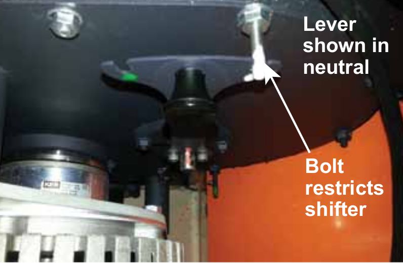
4 Payload Integration Guide                                                                               19

   4.1 System Architecture . . . . . . . . . . . . . . . . . . . . . . . . . . . . . . . . . . . . .      19

   4.2 Mechanical Mounting      . . . . . . . . . . . . . . . . . . . . . . . . . . . . . . . . . . . .   22

        4.2.1 Payload Integration Guidelines . . . . . . . . . . . . . . . . . . . . . . . . . . . .      22

   4.3 Electrical Integration . . . . . . . . . . . . . . . . . . . . . . . . . . . . . . . . . . . . .   23

   4.4 Software Integration . . . . . . . . . . . . . . . . . . . . . . . . . . . . . . . . . . . . .     24

5 Maintenance                                                                                             29

   5.1 Battery & Charging . . . . . . . . . . . . . . . . . . . . . . . . . . . . . . . . . . . . . .     29

        5.1.1 General     . . . . . . . . . . . . . . . . . . . . . . . . . . . . . . . . . . . . . . .   29

        5.1.2 Long-term Storage . . . . . . . . . . . . . . . . . . . . . . . . . . . . . . . . . .       29

6 Contact                                                                                                 30

Rev. 1.0.0                                           3                                       Warthog UGV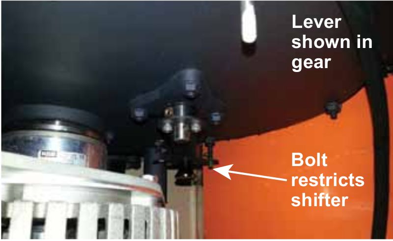
INTRODUCTION
Clearpath Robotics Warthog is a rugged, all-terrain unmanned ground vehicle capable of travelling on land
and in water. Warthog fully supports the Robot Operating System (ROS) and can be equipped with a variety
of payloads, including sensors and manipulators, to accommodate a wide range of robotics applications in
mining, agriculture and environmental monitoring. This guide contains information about the setup, safe
operation, and maintenance of your Warthog. Please read the entire manual and safety warnings prior to
operating the Warthog.

What’s Included
Included with each Warthog are the following:

    • 1x Warthog UGV
          – Onboard computer
          – User Panel with power, Ethernet, Serial(RS232) and USB connectivity
          – 48V Lead Acid Battery Pack
          – Battery Charger
    • 1x Futaba Remote Control (R/C)
    • 1x Warthog User Manual
    • 1x Wireless Stop Remote

Rev. 1.0.0                                         4                                       Warthog UGV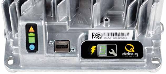
Hardware Overview
Please see Figure 1 for a view of some of Warthog’s key external-facing features.

                                                 Payload Integration
                                                        Area

                                    RC Antenna
                                                                User Panel
                                                                                    Wifi Antenna

                           E-Stop
  Battery Charger Access

        E-Stop
                                                                                                  E-Stop
   Front Light

                                                                                              E-Stop

                                                                                             Front Light

                                           Figure 1: Warthog Hardware Overview

Rev. 1.0.0                                                     5                              Warthog UGV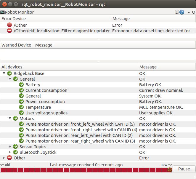
Battery Charger

Please see Appendix for information about the provided charger.

Bilge Pumps

The Warthog has two bilge pumps, with one situated in each of the drive units underneath the motor.

The bilge pumps are used to remove water from the main chassis and drive units during operation in water.
At initial startup, an audible sound can be heard from the bilge pumps being initiated. These pumps are
an automatic pumping system that check for water levels inside the drive units. The pumps automatically
come on every two minutes and check for water levels. If the water level inside the drive unit exceeds a
predetermined level, the pumps will remain on, otherwise they will shut off. During prolonged use in water,
some water may appear in the drive unit. This is normal and acceptable.

This outlet leads from the pump to the exterior of the Warthog. It is used to remove excess water from the
chassis and drive units. No obstructions should be placed in front of or around this area. Obstruction of water
flow may result in damage to the internal electrical components and loss of function in the Warthog.

User Panel

The User Panel provides access to the user power panel, as well as USB, serial, and ethernet ports. The
power panel can be used to power your payloads. The USB 3.0 and ethernet ports are connected directly
to the onboard PC. To connect a device to the onboard network, it’s suggested to give it a static IP in the
192.168.131.x subnet, avoiding IPs in use by the following pre-existing devices:

 192.168.131.1                       Onboard PC (all ports, br0 network interface).
 192.168.131.2                       Ethernet-connected MCU.
 192.168.131.14                      Front-facing LIDAR (optional).
 192.168.131.13                      Rear-facing LIDAR (optional).

                                Table 1: Warthog Onboard Network Devices

For more information on electrical integration, please see subsection 4.3 on page 23.

Payload Integration Area

All payloads should be mounted to the central chassis when traversing through water to prevent rolling. The
primary payload of the unit should be placed on the central chassis. If necessary loading can be placed on
the drive units however payloads should not exceed 50 lbs on each drive unit.

For more information and guidance on mounting payload structures on top of Warthog, please refer to sub-
section 4.2 on page 22.

Rev. 1.0.0                                            6                                         Warthog UGV
Technical Specifications
Key specifications of Warthog are shown in Table 2.

 External Dimensions (L x W x H)    1.52 x 1.38 x 0.83 m (4.9 x 4.5 x 2.72 ft )
 Base Weight                        280 kg (551 lbs)
 Ground Clearance                   254 mm (10 in)
 Max Payload                        272 kg (600 lbs)
 Max Incline                        35-45°
 Max Speed                          18 km/h (11 mph)
 Suspension                         Geometric Passive Articulation
 Drive Configuration                4x4 Skid Steer
 Operating Environment              Outdoor
 Traction                           24” Argo tire (24” Turf tire or 12” wide Quad Track System optional)
 Battery Chemistry                  AGM sealed lead acid (Li-ion optional)
 Capacity                           105 Ah at 48 V, expandable to 200 Ah with Li-ion option
 Nominal Run Time                   Lead acid: 2.5 hrs, Li-ion: 6 hrs
 Charge Time                        4 Hours approx
 User Power                         5 V, 12 V Fused (24 V, 48 V optional)
 Control Modes                      Remote control, computer controlled velocity commands, indoor/outdoor au-
                                    tonomy packages
 Feedback                           Battery voltage, motor currents, wheel odometry, control system status, tem-
                                    perature, safety status
 Communication                      Ethernet, USB, Remote Control, Wi-Fi
 Drivers and APIs                   Packaged with ROS Indigo (includes RViz, Gazebo support), Matlab API
                                    available

                                 Table 2: Warthog System Specifications

Rev. 1.0.0                                             7                                      Warthog UGV
GETTING STARTED
The first step is to read this manual and safety warnings. The next step is to power up your Warthog and have
some fun driving it around!
Twist the red power button on the back of Warthog. Once the body lights are flashing red, twist (to reset)
all four stop buttons (if necessary), and press go on the Wireless Stop Remote (next section). In a moment,
Warthog should go to solid red lights in back, and solid white in front.
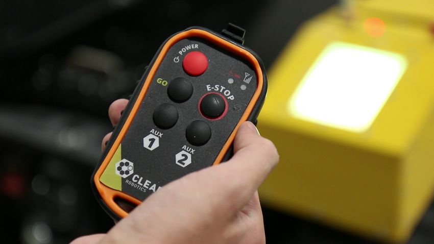
Wireless Stop Remote
Included with the Warthog is a wireless stop remote, shown in Figure Figure 2 below, which is needed for
operation. If the wireless stop remote is out of range ( 900m), it will cause the system to stop. Likewise, if the
wireless stop remote is inactive for 15 minutes, it will cause the system to stop.
To turn on the remote, hold down the red ’POWER’ button until the battery and signal strength flash. The
vehicle’s lights will give an indication of the state of the stop system.
To assert a stop during operation, simply press the ’Stop’ button which will be verified by the Warthog’s lights
flashing red. Similarly, to release the stop system to resume operation, press ’Stop’ followed by ’GO’.
Figure 2: Warthog’s Wireless Stop Remote
If you’re not seeing any change in behaviour, please contact our support team.
Rev. 1.0.0 8 Warthog UGVFutaba Controller
The long range remote control (RC) Futaba radio transmitter can be used to tele-operate the Warthog. To
begin, slide the power switch to the ON position which is labelled in Figure ??.
Caution: The speed adjustment knob should be turned initially all the way to the left while familiarizing yourself
with the transmitter and slowly increasing it to get it moving.
The position of the speed adjustment scale is shown in Figure 4 as ’CH4’. The transmitter needs to be enabled
which is done using the Enable/Disable switch that is a three position switch where only the down position
enables it.
The left joy stick is used for the forward and reverse motion of the robot and the right joystick is used for
turning.
Antenna
Speed Adjustment
Enable/Disable
Left/Right
Forward/Reverse
Power&Display
switch
Figure 3: Futaba Radio Transmitter
If you’re not seeing any action, check Contact on section 6 to get in touch with support.
Rev. 1.0.0 9 Warthog UGVEnable/Disable Control
Speed Scale
Figure 4: Futaba Radio Transmitter Screen
Body Lights
Warthog includes eight RGB body lights, stacked in a pair on each corner of the chassis. These lights ex-
press system status according to Table 3, but in the absence of one of the low-level conditions, they can be
commanded from ROS to display indications from autonomy or other higher-level software.
See http://wiki.ros.org/warthog_base for information on commanding the body lights.
Rev. 1.0.0 10 Warthog UGVSolid red The MCU is not in contact with the computer. That is, the rosserial connection
is not active. This condition will be seen briefly on startup while Warthog’s
computer is booting up. If it persists, or is seen after initialization, either
the base node on the PC has crashed, the network switch has failed, or a
serious MCU error has occurred. If you suspect one of these conditions,
please contact our support team.
Red flashing Stop circuit is broken. Twist the mushroom buttons to ensure that they are
unlatched, and check any external stop hardware, if present.
Flashing yellow Motor drivers not yet ready to drive. The motors have a brief initialization
sequence which must complete after a stop condition clears before they are
ready to drive. If this condition persists, please contact our support team.
Headlights/taillights When Warthog is ready to drive, the front will change from red to white. The
intensity of the head and tail lights will increase slightly when actually in mo-
tion. This is the status which may be overridden by publishing your own light
patterns to the cmd_lights ROS topic.
Table 3: Warthog Body Light Indications
Wireless Access
To get Warthog connected to your local wifi, you must first access the internal computer using a wired connec-
tion. Connect to one of the the network ports with a standard ethernet cable. Now, set your laptop’s ethernet
port to a static IP such as 192.168.131.51, and connect via SSH to administrator@192.168.131.1. The default
password is clearpath.
Once connected via wire, execute connmanctl to enter the command line interface for Connman, from which
you can configure Warthog to either join an existing network, or supply its own standalone access point. An
example session to connect to an existing network:
connmanctl > enable wifi
connmanctl > scan wifi
connmanctl > services
connmanctl > agent on
connmanctl > connect wifi_123456_123456789123456789_managed_psk
After the connect line, connman will prompt you for your network’s passphrase. Once connected, connman
will remember and attempt to reconnect on successive power-ons.
Rev. 1.0.0 11 Warthog UGVRemote ROS Connectivity Now that Warthog is on the wireless network, you can access it via SSH or as a remote ROS master. Note that in the default configuration, the background ROS process running on Warthog launches with the robot_upstart package, which is configured to set the ROS_HOSTNAME environment variable to the Warthog PC’s hostname. If your network resolves hostnames properly, connecting should be a matter of executing the following two lines in your desktop (or sourcing a script containing these lines): export ROS_MASTER_URI=http://cpr-warthog:11311 # Your robot’s hostname export ROS_IP=192.168.131.1 # Your computer ’s wireless IP address If your network doesn’t resolve hostnames, you may need to add the following line to your /etc/hosts file: 192.168.131.1 cpr-warthog # The robot’s wireless IP address. Once everything is set up correctly, try running rostopic list, which will verify that your machine can see the robot’s ROS master, and rostopic echo /mcu/status, which will verify that the robot PC can see your machine in order to stream topics to it. Please contact Clearpath Support if guidance is required in selecting and executing a remote access strategy. For more general details on how ROS works over TCP with multiple machines, please see: http://wiki.ros.org/ROS/Tutorials/MultipleMachines For help troubleshooting a multiple machines connectivity issue, see: http://wiki.ros.org/ROS/NetworkSetup Visualizing Warthog To command or observe Warthog from your desktop computer, first set up a basic ROS installation. See the following page for details: http://wiki.ros.org/indigo/Installation/Ubuntu When your ROS install is set up, install the Warthog desktop packages: sudo apt-get install ros-indigo -warthog -desktop Once your remote access to Warthog’s ROS master is configured (as above), you can launch rviz, the stan- dard ROS robot visualization tool: roslaunch warthog_viz view_robot.launch From within rviz, you can use interactive markers to drive Warthog, you can visualize its published localization estimate, and you can visualize any attached sensors which have been added to its robot description XML (URDF). Rev. 1.0.0 12 Warthog UGV
From your desktop, you can also launch the standard RQT Robot Monitor, which reports the diagnostic output
from Warthog’s self-monitoring capabilities, as shown in Figure 5:

rosrun rqt_robot_monitor rqt_robot_monitor

                                           Figure 5: Robot Monitor

Drive Train
The Warthog has the ability to be put into neutral which is controlled be the four levers (two per side) in the
rockers. The lever can be seen in Figure 6. Use the bolts to restrict the lever from moving as down in Figure 7
where the drivetrain is in neutral. The grove for the neutral position is marked with white and the bolt is also
marked. Pull the handle on the lever to move it into gear which can be seen in Figure 8. Ensure the lever is
in the green grove. If the lever is difficult to move, rock the Warthog back and forth. Do not try to force the
lever to move.

Rev. 1.0.0                                            13                                         Warthog UGV
Figure 6: Drivetrain lever
Figure 7: Drivetrain in Neutral
Rev. 1.0.0 14 Warthog UGVFigure 8: Drivetrain in Gear Rev. 1.0.0 15 Warthog UGV
SAFETY CONSIDERATIONS
Warthog is a powerful, heavy, fast moving robotic platform. Please read the following safety information
carefully.
General Warnings
For the safety of yourself and others, always conduct initial experiments and software development with the
motors not engaged. Whenever the robot is not being operated and the motors are engaged, keep it in a stop
state. Do not ride on the vehicle, it can accelerate and brake quickly.
When starting out, favour slower wheel speeds. Warthog’s control loops can accurately maintain velocities
as low as 0.1 m/s. Operating at such speeds will give you more time to react if things don’t go quite as you
expect.
When enabling the system using the GO button on the wireless remote, be sure to stand well back from the
Warthog. User code running on the Warthog may still be trying to command the motors, and this can result in
sudden and unexpected movement of the vehicle. Be prepared to stop the system again using the wireless
remote.
Maneuverability in Water
Before entering the water it is important to ensure that:
• Bilge pumps are functioning properly. See Bilge Pump section on page 6 for more information.
• The side panels and top cover are properly fastened down
• All access panels are fastened down
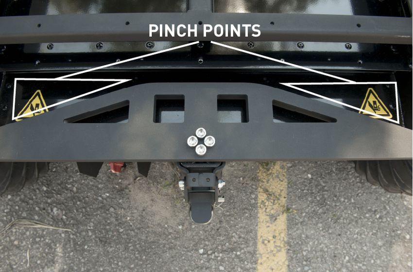
Pinch Points
When operating the Warthog it is important to maintain a safe distance away from the unit. The suspension
seen in Figure 9 has the ability to pivot. Do not place fingers anywhere along the suspension link as it can
result in injury.
Rev. 1.0.0 16 Warthog UGVFigure 9: Warthog Pinch Points Stop Buttons The Stop system on the Warthog has two major components: The hardwired Stop switches and the wireless stop remote. Hardwired Stop Pressing down one of the 4 red mushroom Stop buttons around the Warthog will disable power to the SEVCON devices (Key switch input on PIN 1). This disables the large contactors and also enables the brakes (passive, spring activated when not powered). The status indicator lights around the Warthog will flash red. To reset a Stop button, the top of the button should be twisted until the button pops out again. The GO button on Wireless remote must then pressed. The Warthog is fully enabled once a relay click is heard, and the front lights change to white. Wireless Remote Stop To operate the Warthog, the wireless remote stop also has to be powered on (by holding the Power button for at least 1 second). The remote Stop button toggles the Stop status, so it must be pressed once to enable Stop, and pressed again to return to an Stop reset ready state, much like the hardwired Stop buttons. The GO button on the remote will then reset the stop condition. The wireless remote will shut itself off after 15 minutes of inactivity. Thus, the user is suggested to toggle the reset button (or either AUX 1 or 2) every few Rev. 1.0.0 17 Warthog UGV
minutes to keep the remote awake. This is done to ensure that the user does not forget about the wireless
remote, leading to a safety hazard.

Always ensure the Stop button is accessible at all times. Avoid mounting payloads that extend over the rear
of Warthog and would occlude the Stop buttons.

Electrical System
The largest electrical safety consideration with the Warthog system is the VBat connection. As it is pulled
straight from the batteries, it may have a voltage of 48V (depleted) - 62V (Charging) and can be used to
power large external devices. This voltage can cause electrical shock if directly contacted, and is fused
internally with an inline fuse at 10A. In general, take care to connect or disconnect devices preferably only
when the entire system is powered off via the external switch on the rear (main power switch).

Take note that triggering a Stop condition only disables voltage to the SEVCON drivers and motors, not the
rest of the system which includes the connectors.

The labelled status LEDS on the user panels indicate status of the system voltages. If an LED is not lit, most
likely a system fuse has blown, and contacting Clearpath support is the best option.

To ensure saftey, please also observe the following precautions:

    •   Do not tamper with the battery terminals or wiring.
    •   Consult Clearpath Robotics support if you need to service the battery pack.
    •   Do not lay tools or other objects on top of the battery.
    •   Do not move the robot while charging the battery.
    •   Charge the battery only with the charger provided by Clearpath Robotics.
    •   Please dispose of the batteries properly, or return the batteries to Clearpath Robotics to do so.

Rev. 1.0.0                                             18                                        Warthog UGV
PAYLOAD INTEGRATION GUIDE
If you want to attach custom hardware to Warthog, you will have to take care of mechnical mounting, electrical
supply, and software integration. This section aims to equip you with respect to these challenges.
System Architecture
Like most robotic systems, Warthog has an onboard PC coupled to a custom microcontroller board. The micro-
controller board handles IO, system and battery monitoring, and provides an interface to the CAN-controlled
motor drivers. See the diagram in Figure 10 for more details.
Wireless
AP Futaba Body Lights Wireless Stop Stop button
USB
breakouts
On-board
Serial Computer MCU Stop system
breakouts
Ethernet
breakouts
Stop System
DIO
Ethernet
USB/serial
Left Motor Driver Right Motor Driver Stop reset button
CANBUS
Figure 10: System Architecture
Using ROS to interface with the Warthog, the ROS API described in Table 4 can be used and the node
connections can be seen in Figure 11
Rev. 1.0.0 19 Warthog UGVTopic Message Type Purpose
/cmd_vel geometry_msgs/Twist Input to Warthog’s kinematic controller. Publish
here to make Warthog go.
/odometry/filtered nav_msgs/Odometry Published by robot_localization, a filtered local-
ization estimate based on wheel odometry (en-
coders) and integrated IMU.
/imu/data sensor_msgs/IMU Published by imu_filter_madgwick, an orientation
estimate based on Warthog’s internal gyroscope,
accelerometer, and magnetometer.
/status warthog_msgs/Status Low-frequency status data for Warthog’s systems.
This information is republished in human readable
form on the diagnostics topic and is best con-
sumed with the Robot Monitor.
/cmd_lights warthog_msgs/Lights Input to controlling the Warthog’s body lights when
not in an error state.
/SIDE/speed std_msgs/Float64 Input velocity for each motor where SIDE is either
left or right. This should not be published to di-
rectly, commands from /cmd_vel will be converted
to this.
/SIDE/status/speed std_msgs/Float64 Reported velocity from each motor’s encoder
where SIDE is either left or right.
/SIDE/status/fault std_msgs/Bool Reported state from each motor controller where
SIDE is either left or right.
/SIDE/status/motor_temperature std_msgs/Int32 Reported temperature from each motor controller
where SIDE is either left or right.
Table 4: Warthog ROS API Topics
Rev. 1.0.0 20 Warthog UGVFigure 11: Warthog Node and Topic connections Rev. 1.0.0 21 Warthog UGV
Mechanical Mounting
The payload integration area can be used to mount external payloads on top of the Warthog.

Payload Integration Guidelines

    • 27.75” is the maximum allowed width of any installed payload (this assumes that the payload is also
      centered across the width of the UGV chassis.
    • No part of the payload may extend over the sheet metal housings of the drive units or into the small
      ( 2”) gaps between the chassis and drive units. Damage to both the UGV and the payload WILL result.
    • The chassis has a removable access cover measuring 46.25” x 26.25”. This access cover is supported
      underneath by two adjustable cross members. Regardless of payload, it is imperative that both cross
      members remain installed (approximately evenly spaced) to provided required support to the access
      cover. Consider that any payload installed above the top deck will prevent access to the chassis
      through the access cover, without first removing the installed payload.
    • The rotation of the suspension differential link in the horizontal plane will allow the payload to extend
      beyond the chassis top deck in both fore and aft locations. The amount of this payload extension
      (overhang) is dependent on several factors, including the weight and method of attachment of the
      payload as well as the terrain in which the UGV will operate. Ensure that the amount of overhanging
      payload allows the UGV to operate safely and does not contact the terrain, especially when crossing
      steep and/or deep gullies.
    • The available internal chassis volume is approximately 17.5” long x 26” wide x 9.5” high. This space is
      located at the center of the chassis between two battery packs. Consider that anything placed inside
      the chassis MUST be secured as to not move or shift during UGV operation. Any payload secured
      inside the chassis must also be insulated from coming into contact with the battery wiring and terminals.

Permanent damage resulting from custom modifications to the mounting plate is not covered under warranty
and may not be supported by Clearpath Support. Please contact our support team if you require assistance
or have any questions relating to custom modifications.

Rev. 1.0.0                                           22                                         Warthog UGV
Electrical Integration
The user power receptacles located in the User Panel are capable of supplying 5Vdc, 12Vdc, and unregu-
lated battery voltage (approximately 48Vdc) for powering Warthog’s payloads. See Figure 12 for an labelled
illustration and Figure 13 the pin assignments. Ensure you select contact appropriate for the gauge of wire
used. The electrical system for the chassis can be seen in Figure 14. Additionally, left and right drive units
electrical system is described in Figure 15 and Figure 16 respectively.
HDMI
Serial
Ethernet
USB 3.0
User Power
Figure 12: Warthog User Panel
Risk of Fire
For continued protection against risk of fire, always replace fuses only with those of the same type and rating.
Unregulated Rail
The unregulated battery output may range from as low as 40Vdc up to 60Vdc or more depending on the state
of charge of the battery pack and the electrical loading on the system. Ensure any accessories connected to
that rail are able to deal with unregulated battery voltages.
Rev. 1.0.0 23 Warthog UGVSoftware Integration ROS has a large ecosystem of sensor drivers, some of which include pre-made URDF description and even simulation configurations. Please see the following page on the ROS wiki for a partial list: http://wiki.ros.org/Sensors For the best experience, consider purchasing supported accessories from Clearpath Robotics for your Warthog, which will include simulation, visualization, and driver support. However, we will happily help you get started with integrating your own devices as well. Rev. 1.0.0 24 Warthog UGV
����������������������

                                                  ����������

                  ���                          ���             ���                            ���

                            �             �                               �               �
                                                    ����
             ��         �          �          �                       �           �           �     ���
                                                        ���                    ��
                             �           �                                �               �
                  ���                         ���              ���                            ���

                                               �����������

                                                            ���                           ���

                                                                      �               �

                                                                  �           �           �       ���
                                                     ���                  ��
                                                                      �               �
                                                            ���                           ���

             �����������������������������������
             ��������������������������������������������

                        Figure 13: Warthog Power User Connector Pinout

Rev. 1.0.0                                              25                                                Warthog UGV
�����������������
���
���
�� �������
���� ������
���������� ����
������
����� �����
������ ������
�������������
����������������
������������� �������� ��������������������
���������������� ��������
���
��������������
������������
�������������
���� ���
����������������
���������������������
���������� �����������
��������
�����������������
�����������������
����������������� ���������
����
����������
�����������
Figure 14: Warthog Chassis Electrical System
Rev. 1.0.0 26 Warthog UGV���������������
�� ��
������������ ������������
���������� ������
���
������
����
���������� ������
���� ������
��������� ���������
�������
���������������
���������
�������������
����� ����� ����� ��
����������������
�� ���������������
���������
������
����� �����
�������
�������������
����� �����
Figure 15: Warthog Left Drive Unit Electrical System
Rev. 1.0.0 27 Warthog UGV����������������
�� ��
������������ ������������
���
���������� ������
���� ������
���� ���������� ������
������
���������
�������������
����� �����
����� �� ����������
��
������
����� �����
������������
�������
����� �����
Figure 16: Warthog Right Drive Unit Electrical System
Rev. 1.0.0 28 Warthog UGVMAINTENANCE
Battery & Charging
General
Warthog contains 48V lead-acid or lithium-ion battery packs. Each battery pack consists of four 12V lead-acid
or lithium-ion batteries.
Battery configuration may vary with each unit. In order to maximize performance it is important to ensure that
the battery level across each set of lead-acid or lithium-ion batteries is within 0.1-0.2V of each other. If the
battery packs exceed this tolerance, it is advised to charge them to within tolerance before wiring these packs
in parallel. The overall battery life will vary depending upon the usage of the unit.
Always exercise caution and observe the following safety practices connecting, disconnecting or handling
batteries:
• Batteries are high voltage, high current
• Battery packs must be properly fastened down to ensure they do not move when the Warthog is in
operation.
• Ensure that the battery packs are evenly distributed throughout the Warthog to maximize stability.
• Battery levels on the unit should be checked on a regular basis. It is important to maintain the battery
voltage at a suitable level for proper operation.
• When additional battery packs are added to the system it is important to connect the positive terminal
first to the main power of the Warthog before connecting ground.
• When installing additional battery packs, disconnect the ground on all battery packs presently in the
unit before connecting the positive terminal of the new battery packs.
Long-term Storage
When storing Warthog for long periods of time, its important to properly maintain the batteries to fully maximize
their life. Consider one of the following two procedures when placing Warthog in long-term storage:
• Fully charge Warthog, turn it off and put it into storage. Once a week, connect power to the charger
and allow the charger to top up the battery for an hour or so.
• Fully charge Warthog, turn it off and put it into storage, but leave the charger connected and powered
the entire time Warthog is in storage. The charger will monitor the battery and will automatically charge
it up as needed.
Please contact Clearpath Robotics for additional information about Warthog’s battery pack.
Rev. 1.0.0 29 Warthog UGVCONTACT Clearpath is committed to your success with Warthog. Please get in touch with us and we’ll do our best to get you rolling again quickly: support@clearpathrobotics.com. To get in touch with a salesperson regarding Warthog or other Clearpath Robotics products, please email sales@clearpathrobotics.com. If you have an issue that is specifically about ROS and is something which may be of interest to the broader community, consider asking it on answers.ros.org. If you don’t get a satisfactory response, please ping us and include a link to your question as posted there. If appropriate, we’ll answer in the ROS Answers context for the benefit of the community.
APPENDIX 1

Delta-Q IC650
650W Industrial Battery Charger

Product Manual
This manual contains important safety and operating
instructions for the Delta-Q IC650 Industrial Battery
Charger. Please read this information in its entirety before
using your Delta-Q IC650 Charger. For technical support,
please contact the manufacturer of your vehicle or
machine, as their version of this charger may require special
instructions.

            Warning                                                        Attention
Use charger only with an algorithm selected that is             Utiliser le chargeur seulement avec un algorithme
appropriate to the specific battery type. Other usage may       approprié au type spécifique de batterie. D´autres types
cause personal injury and damage. Lead acid batteries           de batteries pourraient éclater et causer des blessures
may generate explosive hydrogen gas during normal               ou dommages. Les batteries peuvent produire des gaz
operation. Keep sparks, flames, and smoking materials           explosifs en service normal. Ne jamais fumer près de la
away from batteries. Provide adequate ventilation during        batterie et éviter toute étincelle ou flamme nue à proximité
charging. Never charge a frozen battery. Observe all battery    des batteries. Fournissez une ventilation adéquate du
manufacturers’ specific precautions (e.g. maximum charge        chargement. Ne jamais charger une batterie gelée. Prendre
rates and if cell caps should be removed while charging).       connaissance des mesures de précaution spécifiées par le
                                                                fabricant de la batterie, p. ex., vérifier s´il faut enlever les
                                                                bouchons des cellules lors du chargement, et les taux de
                                                                chargement.

            Danger
Risk of electric shock. Connect charger power cord to an
outlet that has been properly installed and grounded in                    Danger
accordance with all local codes and ordinances. A grounded
                                                                Risque de décharge électrique. Ne pas toucher les parties
outlet is required to reduce risk of electric shock—do
                                                                non isolées du connecteur de sortie ou les bornes non
not use ground adapters or modify plug. Do not touch
                                                                isolées de la batterie. Toujours connecter le chargeur à une
uninsulated portions of output connector or uninsulated
                                                                prise de courant mise à la terre. Déconnectez la source
battery terminals. Disconnect the AC supply before making
                                                                AC avant de faire ou défaire les connections à la batterie
or breaking the connections to the battery. Do not open
                                                                en chargement. Ne pas utiliser le chargeur si le cordon
or disassemble charger. Do not operate this charger if the
                                                                d’alimentation AC est endommagé ou si le chargeur est
AC supply cord is damaged or if the charger has received
                                                                abîmé suite à une chute ou autre indicent. Ne pas ouvrir
a sharp blow, been dropped, or is damaged in any way.
                                                                ni désassembler le chargeur – référer toute réparation
Refer all repair work to the manufacturer, or qualified
                                                                aux personnes qualifiées. Cet appareil n’est pas destiné
personnel. This charger is not intended for use by persons
                                                                à un usage par des personnes (dont les enfants) avec des
(including children) with reduced physical, sensory or
                                                                facultés motrices, sensorielles ou mentales réduites, ou
mental capabilities, or lack of experience and knowledge on
                                                                ayant une expérience et des connaissances insuffisantes,
electrical systems and battery charging, unless they have
                                                                à moins qu’elles sont sous la supervision ou reçoivent les
been given supervision or instruction concerning use of the
                                                                instructions sur l’utilisation de l’appareil d’un répondant
charger by a person responsible for their safety. Children
                                                                garant de leur sécurité. Les enfants devraient être surveillés
should be supervised to ensure that they do not play with
                                                                afin qu’il ne jouent en aucun temps avec l’appareil.
the charger.

© 2013 Delta-Q Technologies Corp. All rights reserved.
(PN: 710-0138 Rev 1 Date: 04/04/2013)                                                                                          1
Delta-Q IC650 Charger Manual
Maintenance Instructions
1. Do not expose charger to oil, dirt, mud or direct heavy water spray when cleaning the vehicle or machine.
2. The enclosure of the charger meets IP66, making it dust-tight and protected against powerful water jets. The AC inlet
connection itself, when mated, is rated to IP20, which is not protected against water. Protect the AC connection if
used in wet or dusty environments.
3. If the detachable input power supply cord set is damaged, replace with a cord that is appropriate for your region:
North America: UL or CSA listed / approved detachable cord at least 1.8m in length (≥ 6 feet), 3 conductor,
16AWG minimum and rated SJT; terminated in a grounding type IEC 60320 C14 plug rated 250V, 13A minimum.
All other regions: Safety approved detachable cord, 3 conductor, 1.5mm² minimum, rated appropriately for
industrial use. The cord set must be terminated on one end with a grounding type input connector appropriate
for use in the country of destination and, on the other end, an output grounding type IEC 60320 C14 plug.
Operating Instructions
The charger may become hot during charging. Use hand protection to safely handle the charger during charging.
Extension cords must be 3-wire cord no longer than 30m (100’) at 10 AWG or 7.5m (25’) at 16 AWG, per UL guidelines.
Fault / Error / USB Indicator
Battery Charging Indicator
Charging Output Indicator2
AC Power Indicator
Charge Profile / Error Display3
USB Host Port1
Select Charge Profile Button4
Solid red = Charger fault
Solid blue = AC power available
See display panel for details
Flashing amber = External error condition - caution Flashing green = Low state of charge
See display panel for details Solid green = High state of charge
Flashing green = USB port active Flashing green = High state of charge
Solid green = Safe to remove USB flash drive Solid green = charge completed
1. The USB Host Port allows data to be transferred to and from the charger using a standard USB flash drive, including the
downloading of charge tracking data and updating of the charger’s software and / or charge profiles.
2. The Charging Output Indicator means that the charger output is active, and there is a potential risk of electric shock.
3. The Charge Profile / Error Display shows one of four possible codes to indicate different conditions:
‘F’ codes meaning that an internal fault condition has caused charging to stop.
‘E’ codes meaning that an external error condition has caused charging to stop.
‘P’ code meaning that the charger programming mode is active.
‘USB’ code meaning that the USB interface is active, and the USB flash drive should not be removed.
The ‘E,’ ‘F’ and ‘P’ codes will appear, then are followed by three numbers and a period to indicate different conditions (e.g.
E-0-0-4). See the “Charger Fault Codes” or “Charger Error Codes” sections for details on these conditions and their solutions.
4. The Select Charge Profile Button is used to select a charge profile from those stored on the charger. Up to 25 charge
profiles can be stored. See the “Selecting A Charge Profile” section for instructions.
www.delta-q.com 2Delta-Q IC650 Charger Manual
Selecting A Charge Profile
1. Disconnect AC input from the charger, or from the wall *Process will time out and profile will remain unchanged if
outlet. Wait 30 seconds for the input relay to open. there is 15 seconds of inactivity, a profile number is allowed to
display three times, or if AC power is cycled.
4. Once desired charging profile is displayed, press and hold
button for 10 seconds (see Figure 3) to confirm selection
and exit Profile Selection Mode.
Figure 1:
Disconnect AC 5. Press the Select Charge Profile Button to check that the
input from the desired profile is selected.
charger.
Use this table to record the charging profiles on your
charger.
Model: IC650-___________________
Serial No.: DQS_____________________
2. While reconnecting AC input, press and hold the Select
Charge Profile Button. Hold the button until Error Indicator Profile No. Battery Type
is on and Battery Charging Indicator starts flashing.
Figure 2:
Reconnect AC
input while
holding the
Select Charge
Profile Button.
3. Press and release the Select Charge Profile Button to
advance through charging profiles loaded on the charger.
The selected charging profile will be displayed up to three
times (e.g. “P-0-1-1” for Profile 11).*
Figure 3:
Press the
Select Charge
Profile Button
to advance
through
the charge
profiles. Hold
the button for
10 seconds to
confirm your
selection.
Charger Fault Codes
Code Solution
F-0-0-1, F-0-0-2 Internal charger fault. Remove AC and battery for minimum 30 seconds and retry charger. If it fails
F-0-0-3, F-0-0-4 again, please contact the manufacturer of your vehicle or machine.
F-0-0-6
Visit www.youtube.com/deltaqtechnologies for instructional videos. 3Delta-Q IC650 Charger Manual
Charger Error Codes
Code Description Solution
E-0-0-1 Battery high voltage Check the battery voltage and cable connections. Check battery size and condition.
E-0-2-1 This error will automatically clear once the condition has been corrected.
E-0-0-2 Battery low voltage Check the battery voltage and cable connections. Check battery size and condition.
E-0-2-2 This error will automatically clear once the condition has been corrected.
E-0-0-3 Charge timeout Possible causes: Charger output reduced due to high temperatures, poor battery
caused by battery health, very deeply discharged battery and /or poorly connected battery. Possible
pack not reaching solutions: Operate at lower ambient temperature. Replace battery pack. Check DC
required voltage connections. This error will automatically clear once the charger is reset by cycling
within safe time DC.
limit.
E-0-0-4 Battery could not Check for shorted or damaged cells. Replace battery pack. Check DC connections.
meet minimum This error will automatically clear once the charger is reset by cycling DC.
voltage
E-0-0-5 Charger temperature Ensure sufficient cooling air flow and reset charger by disconnecting DC or AC for 10
limit exceeded minutes, then reconnect. This error will automatically clear once the condition has
been corrected.
E-0-0-6 Low AC voltage error Connect charger to an AC source that provides stable AC between 85 - 270 VAC / 45-
65 Hz. This error will automatically clear once the condition has been corrected.
E-0-0-7 Battery amp hour Possible causes include poor battery health, very deeply discharged battery, poorly
limit exceeded connected battery, and / or high parasitic loads on battery while charging. Possible
solutions: Replace battery pack. Check DC connections. Disconnect parasitic loads.
This error will automatically clear once the charger is reset by cycling DC.
E-0-0-8 Battery temperature Possible battery temperature sensor error. Check temperature sensor and
is out of range connections. Reset charger. This error will automatically clear once the condition
has been corrected.
E-0-1-2 Reverse polarity Battery is connected to the charger incorrectly. Check the battery connections. This
error error will automatically clear once the condition has been corrected.
E-0-1-6 USB operation failed Software upgrade failure or script operation failure. Ensure the USB flash drive is
E-0-1-8 properly formatted and retry inserting the USB flash drive into the charger.
E-0-2-6
E-0-2-3 High AC voltage Connect charger to an AC source that provides stable AC between 85 - 270 VAC / 45-
error (>270VAC) 65 Hz. This error will automatically clear once the condition has been corrected.
E-0-2-4 Charger failed to The charger has failed to turn on properly. Disconnect AC input and battery for 30
initialize seconds before retrying.
E-0-2-5 Low AC voltage AC source is unstable. Could be caused by undersized generator and /or severely
oscillation error undersized input cables. Connect charger to an AC source that provides stable
AC between 85 - 270 VAC / 45-65 Hz. This error will automatically clear once the
condition has been corrected.
www.delta-q.com 4You can also read