PCA9615 2-channel multipoint Fast-mode Plus differential I2C-bus buffer with hot-swap logic Rev. 2 - 16 September 2021

Page created by Elmer Jordan
 
CONTINUE READING
PCA9615 2-channel multipoint Fast-mode Plus differential I2C-bus buffer with hot-swap logic Rev. 2 - 16 September 2021
PCA9615
                                                                                       2
                2-channel multipoint Fast-mode Plus differential I C-bus
                buffer with hot-swap logic
                Rev. 2 — 16 September 2021                                        Product data sheet

1   General description
                                                                  2
              The PCA9615 is a Fast-mode Plus (Fm+) SMBus/I C-bus buffer that extends the normal
                                       2
              single-ended SMBus/I C-bus through electrically noisy environments using a differential
                         2         2                                                        2
              SMBus/I C-bus (dI C) physical layer, which is transparent to the SMBus/I C-bus protocol
              layer. It consists of two single-ended to differential driver channels for the SCL (serial
              clock) and SDA (serial data).
                                                                            2
              The use of differential transmission lines between identical dI C bus buffers removes
              electrical noise and common-mode offsets that are present when signal lines must pass
              between different voltage domains, are bundled with hostile signals, or run adjacent to
              electrical noise sources, such as high energy power supplies and electric motors.
                           2
              The SMBus/I C-bus was conceived as a simple slow speed digital link for short runs,
              typically on a single PCB or between adjacent PCBs with a common ground connection.
              Applications that extend the bus length or run long cables require careful design to
              preserve noise margin and reject interference.
                    2
              The dI C-bus buffers were designed to solve these problems and are ideally suited for
              rugged high noise environments and/or longer cable applications, allow multiple targets,
              and operate at bus speeds up to 1 MHz clock rate. Cables can be extended to at least
                                                                                2
              3 meters (3 m), or longer cable runs at lower clock speeds. The dI C-bus buffers are
                                                2
              compatible with existing SMBus/I C-bus devices and can drive Standard, Fast-mode, and
              Fast-mode Plus devices on the single-ended side.
              Signal direction is automatic, and requires no external control. To prevent bus latch up,
                                     2
              the standard SMBus/I C-bus side of the bus buffer, the PCA9615 employs static offset,
                                                                               2
              care should be taken when connecting these to other SMBus/I C-bus buffers that may
              not operate with offset.
                                                                                                  2
              This device is a bridge between the normal 2-wire single-ended wired-OR SMBus/I C-
                                    2
              bus and the 4-wire dI C-bus.
              Additional circuitry allows the PCA9615 to be used for ‘hot swap’ applications, where
              systems are always on, but require insertion or removal of modules or cards without
              disruption to existing signals.
              The PCA9615 has two supply voltages, VDD(A) and VDD(B). VDD(A), the card side supply,
              only serves as a reference and ranges from 2.3 V to 5.5 V. VDD(B), the line side supply,
              serves as the majority supply for circuitry and ranges from 3.0 V to 5.5 V.
NXP Semiconductors
                                                                                                                                          PCA9615
                                                                                                                      2
                     2-channel multipoint Fast-mode Plus differential I C-bus buffer with hot-swap logic

                                                                                             dI2C-bus
                                                                                      (differential I2C-bus,
                         single-ended                                                  1 of 2 lines shown)                                         single-ended
                            I2C-bus        VDD(A)1 VDD(B)                   VDD(B)                                   VDD(B)   VDD(B) VDD(A)2          I2C-bus

                                  SCL                                                                                                               SCL

                                               PCA9615                                                                         PCA9615
                                  SDA                                                                                                               SDA
                                                                                        twisted-pair cable
                                  EN                                                                                                                EN

                                                   GND1                                                                           GND2
                                                                                                                                                       aaa-011961
                                              2                                             2                                         2
                     Figure 1. SMBus/I C-bus translation to dI C-bus and back to SMBus/I C-bus

2         Features and benefits
                              2
                     • New dI C-bus buffers offer improved resistance to system noise and ground offset up
                          1
                       to ⁄2 of supply voltage
                                     2               2
                     • 2 channel dI C (differential I C-bus) to Fm+ single-ended buffer operating up to 1 MHz
                       with 30 mA SDA/SCL drive capability
                     • Hot swap (allows insertion or removal of modules or card without disruption to bus
                       data)
                     • EN signal (PCA9615 input) controls PCA9615 hot swap sequence
                     • Bus idle detect (PCA9615 internal function) waits for a bus idle condition before
                       connection is made
                                           2
                     • Compatible with I C-bus Standard/Fast-mode and SMBus, Fast-mode Plus up to
                       1 MHz
                                        2
                     • Single-ended I C-bus on card side up to 540 pF
                                     2
                     • Differential I C-bus on cable side supporting multi-drop bus
                       – Maximum cable length: 3 m (approximately 10 feet) (longer at lower frequency)
                            2
                       – dI C output: 1.5 V differential output with nominal terminals
                       – Differential line impedance (user defined): 100 Ω nominal suggested
                       – Receive input sensitivity: ±200 mV
                       – Hysteresis: ±30 mV typical
                       – Input impedance: high-impedance (200 kΩ typical)
                       – Receive input voltage range: -0.5 V to +5.5 V
                     • Lock-up free operation
                                                                                2
                     • Supports arbitration and clock stretching across the dI C-bus buffers
                                                                        2
                     • Powered-off and powering-up high-impedance I C-bus pins
                     • Operating supply voltage (VDD(A)) range of 2.3 V to 5.5 V with single-ended side 5.5 V
                       tolerant
                                     2
                     • Differential I C-bus operating supply voltage (VDD(B)) range of 3.0 V to 5.5 V with 5.5 V
                       tolerant. Best operation is at 5 V.
                     • ESD protection exceeds 2000 V HBM per JESD22-A114 and 1000 V CDM per
                       JESD22-C101
                     • Latch-up testing is done to JEDEC Standard JESD78 which exceeds 100 mA
                     • Package offering: TSSOP10

PCA9615                                 All information provided in this document is subject to legal disclaimers.                        © NXP B.V. 2021. All rights reserved.

Product data sheet                                 Rev. 2 — 16 September 2021
                                                                                                                                                                      2 / 30
NXP Semiconductors
                                                                                                                                            PCA9615
                                                                                                                                  2
                                2-channel multipoint Fast-mode Plus differential I C-bus buffer with hot-swap logic

3         Applications
                               •   Monitor remote temperature/leak detectors in harsh environment
                               •   Control of power supplies in high noise environment
                                                    2
                               •   Transmission of I C-bus between equipment cabinets
                               •   Commercial lighting and industrial heating/cooling control
                                                                       2
                               •   Any application that requires long I C-bus runs in electrically noisy environments
                               •   Any application with multiple power suppliers and the potential for ground offsets up to
                                   2.5 V

4         Ordering information
Table 1. Ordering information
Type number             Topside                 Package
                        marking
                                                Name                       Description                                                                 Version
PCA9615DP               P9615                   TSSOP10                    plastic thin shrink small outline package; 10 leads;                        SOT552-1
                                                                           body width 3 mm

                       4.1 Ordering options
Table 2. Ordering options
                                                                                                            [1]
Type number            Orderable part              Package                 Packing method                               Minimum order   Temperature range
                       number                                                                                           quantity
                                         [2]
PCA9615DP              PCA9615DPJ                  TSSOP10                 Reel 13" Q1/T1                               2500            Tamb = –40 °C to +85 °C
                                                                           *standard mark SMD
PCA9615DP              PCA9615DPZ                  TSSOP10                 Reel 13" Q1/T1                               2500            Tamb = –40 °C to +85 °C
                                                                           *standard mark SMD
                                                                               [3]
                                                                           SSB

[1]   Standard packing quantities and other packaging data are available at www.nxp.com/packages/
[2]   Discontinuation Notice 202104010DN - PCA9615DPZ is drop in replacement in accordance with PCN 202104008A.
[3]   This packing method uses a Static Shielding Bag (SSB) solution. Material should be kept in sealed bag between uses.

PCA9615                                              All information provided in this document is subject to legal disclaimers.              © NXP B.V. 2021. All rights reserved.

Product data sheet                                              Rev. 2 — 16 September 2021
                                                                                                                                                                         3 / 30
NXP Semiconductors
                                                                                                                                    PCA9615
                                                                                                                  2
                     2-channel multipoint Fast-mode Plus differential I C-bus buffer with hot-swap logic

5         Block diagram

                                                                                       PCA9615                    connect
                                                                 connect
                                                                                                                                          DSCLP
                                  SCL
                                                                                                                                          DSCLM

                                                                                                                                          DSDAP
                                  SDA
                                                                                                                                          DSDAM
                                               VDD(A)

                                   EN                                               I2C-BUS
                                                                                HOT SWAP LOGIC

                                                                                  en
                                VDD(A)                                         POWER-ON RESET,
                                VDD(B)                                        PLUG-IN DETECTION
                                                                               AND DEBOUNCING
                                  VSS

                                                                                                                            002aah765

                     Figure 2. Block diagram (level 0)

                                                                                                  DSCLP, DSDAP

                                                                              VDD

                                                                                                  DSCLM, DSDAM
                                                                                                             aaa-011989

                     Figure 3. Differential output driver simplified circuit

PCA9615                              All information provided in this document is subject to legal disclaimers.                         © NXP B.V. 2021. All rights reserved.

Product data sheet                              Rev. 2 — 16 September 2021
                                                                                                                                                                    4 / 30
NXP Semiconductors
                                                                                                                                    PCA9615
                                                                                                                        2
                         2-channel multipoint Fast-mode Plus differential I C-bus buffer with hot-swap logic

6         Pinning information

                     6.1 Pinning

                                                                    VDD(A)        1                                     10 VDD(B)
                                                                        SDA       2                                     9 DSDAM
                                                                          EN      3        PCA9615DP                    8   DSDAP
                                                                        SCL       4                                     7   DSCLP
                                                                        VSS       5                                     6   DSCLM

                                                                                                        002aah766

                          Figure 4. Pin configuration for TSSOP10

                     6.2 Pin description
                         Table 3. Pin description
                         Symbol        Pin              Description
                                                         2
                         VDD(A)        1                I C-bus side power supply (2.3 V to 5.5 V)
                         SDA           2                card side open-drain serial data input/output
                         EN            3                enable input (active HIGH); internal pull-up resistor to VDD(A)
                         SCL           4                card side open-drain serial clock input/output
                         VSS           5                ground supply voltage (0 V)
                         DSCLM         6                line side differential open-drain clock minus input/output
                         DSCLP         7                line side differential open-drain clock plus input/output
                         DSDAP         8                line side differential open-drain data plus input/output
                         DSDAM         9                line side differential open-drain data minus input/output
                         VDD(B)        10               differential side power supply (3.0 V to 5.5 V)

PCA9615                                    All information provided in this document is subject to legal disclaimers.               © NXP B.V. 2021. All rights reserved.

Product data sheet                                    Rev. 2 — 16 September 2021
                                                                                                                                                                5 / 30
NXP Semiconductors
                                                                                                                               PCA9615
                                                                                                                           2
                          2-channel multipoint Fast-mode Plus differential I C-bus buffer with hot-swap logic

7         Functional description
                         Refer to Figure 2.
                                                                                                          2
                         The PCA9615 is used at each node of the dI C-bus signal path, to provide conversion
                                     2                                      2
                         from the dI C-bus signal format to conventional I C-bus/SMBus, allowing the connection
                                      2
                         of existing I C-bus/SMBus devices as targets or the bus controller. Because the signal
                                             2                                                   2
                         voltages on the I C-bus/SMBus bus side may be different from the dI C-bus side, there
                                                                                                            2
                         are two power supply pins and a common ground. To prevent bus latch-up, the I C-bus/
                                                                                                    2
                         SMBus side employs static offset. Signal direction is determined by the I C-bus/SMBus
                         bus protocol, and does not require a direction signal, as these bus buffers automatically
                         set signal flow direction. An enable pin (EN) is provided to disable the bus buffer, and is
                         useful for fault finding, power-up sequencing, or reconfiguration of a large bus system by
                         isolating sections not needed at all times.
                         Construction of the differential transmission line is not device-dependent. PCB traces,
                         open wiring, twisted-pair cables or a combination of these may be used. Twisted-pair
                         cables offer the best performance. A typical twisted-pair transmission line cable has a
                         characteristic impedance of ‘about 100 Ω’ and must be terminated at both ends in 100 Ω
                                                                                                  2
                         to prevent unwanted signal reflections. Multiple nodes (each using a dI C-bus buffer)
                         may be connected at any point along this transmission line, however, the stub length
                         degrades the bus performance, and should therefore be minimized.

                          2
                     7.1 I C-bus/SMBus side
                                  2
                         The I C-bus/SMBus side of the PCA9615 differential bus buffer is connected to other
                          2
                         I C-bus/SMBus devices and requires pull-up resistors on each of the SCL and SDA
                         signals. The value of the resistor should be chosen based on the bus capacitance and
                         desired data speed, being careful not to overload the driver current rating of 3 mA for
                                                                                             2
                         Standard and Fast modes, 30 mA for Fast-mode Plus (Fm+). The I C-bus/SMBus side of
                         the PCA9615 is powered from the VDD(A) supply pin.

                              2
                     7.2 dI C-bus side differential pair
                                          2
                         In previous I C-bus/SMBus designs, the nodes (Controller and one or more Targets)
                         are connected by wired-OR in combination with a single pull-up resistor. This simple
                         arrangement is not suited for long distances more than 1 meter (1 m) or about 3 feet (3
                         ft), due to ringing and reflections on the un-terminated bus. The use of a transmission line
                         with correct termination eliminates this problem, and is further improved by differential
                                                  2
                         signaling used in the dI C-bus scheme. Each node acts as both a driver and a receiver
                         to allow bidirectional signal flow, but not at the same time. Switching from transmit to
                                                                 2
                         receive is done automatically. The dI C-bus side of the PCA9615 is powered from the
                         VDD(B) supply pin.
                                      2
                         The dI C-bus is also biased to an idle state (D+ more positive than D-) to be compatible
                                   2
                         with the I C-bus/SMBus wired-OR scheme, when not transmitting traffic (data). This
                         allows every node to receive broadcast messages from the Controller, and return
                         ACK/NACK and data in response. Biasing is done with additional resistors, connected
                         to VDD(B) and VSS (the local ground), as shown in Figure 5. The transmission line is
                         terminated in the characteristic impedance of the cable, typically 100 Ω. This is the value
                         defined by three resistors, the other two resistors providing the idle condition bias to the
                         twisted pair.

PCA9615                                       All information provided in this document is subject to legal disclaimers.       © NXP B.V. 2021. All rights reserved.

Product data sheet                                       Rev. 2 — 16 September 2021
                                                                                                                                                           6 / 30
NXP Semiconductors
                                                                                                                                       PCA9615
                                                                                                                      2
                         2-channel multipoint Fast-mode Plus differential I C-bus buffer with hot-swap logic

                                                                DxxxP                                                        DxxxP

                                                                DxxxM                                                        DxxxM
                                                                                        twisted-pair cable

                                                                                                                          aaa-011061
                                     2
                         Figure 5. dI C-bus terminations

                7.2.1 Noise rejection
                                                                          2                                                              2
                         Impulse noise coupled into the I C-bus/SMBus signals can prevent the I C-bus/SMBus
                         bus from operating reliably. The hostile signals may appear on the SCL line, SDA line,
                         or both. Impulse noise may also enter the common ground connection, or be caused by
                         current in the ground path caused by DC power supplies, or other signals sharing the
                         common ground return path. This problem is removed by using a differential transmission
                                                2                                2                          2
                         line, in place of the I C-bus/SMBus signal path. The dI C-bus receiver (at each dI C-
                         bus node) subtracts the signals on the two differential lines (D+ and D-), and eliminates
                                                                             2
                         any common-mode noise that is coupled into the dI C-bus. The receiver amplifies the
                         signals which are also attenuated by the bulk resistance of the transmission line cable
                         connection, and does not rely on a common ground connection at each node.

                7.2.2 Rejection of ground offset voltage
                                                                              2
                         Hostile signals interfere with the I C-bus/SMBus bus through the common ground
                         connection between each node. Current in this ground path causes an offset that may
                                                         2
                         cause false data or push the I C-bus/SMBus signals outside of an acceptable range.
                         Unwanted ground offset can be caused by heavy DC current in the ground path, or
                         injection of ground current from AC signals, either of which may show up as false signals.
                                         2
                         Because the dI C-bus node receiver responds only to the difference between the two
                           2
                         dI C-bus transmission lines, common-mode signals are ignored. There is no need to
                         have a ground connection between each of the nodes, which may be powered locally.
                                                                                                               2
                         Nodes may also be powered by extra conductors (for VDD and ground) run with the dI C-
                         bus signals. Voltage offsets caused by DC current in these additional wires are ignored
                                  2
                         by the dI C-bus receiver, which subtracts the two differential signals (D+ and D-).

                     7.3 EN pin
                         Enable input to connect the device into the bus. When this pin is LOW, the device never
                         connects to the bus, and disconnect the SCL/SDA from differential SCL/SDA. When
                         EN is driven HIGH, and VDD(A) and VDD(B) are stable, the EN pin connects SDA/SCL to
                         differential SDA/SCL after a stop bit or bus idle has been detected on differential line
                                                                        2
                         bus. It should never change state during an I C-bus/SMBus operation because disabling
                         during a bus operation hangs the bus and enabling part way through a bus cycle could
                                       2
                         confuse the I C-bus/SMBus parts being enabled. The EN pin should only change state
                         when the global bus and the buffer port are in an idle state to prevent system failures.

PCA9615                                  All information provided in this document is subject to legal disclaimers.                    © NXP B.V. 2021. All rights reserved.

Product data sheet                                  Rev. 2 — 16 September 2021
                                                                                                                                                                   7 / 30
NXP Semiconductors
                                                                                                                                               PCA9615
                                                                                                                       2
                         2-channel multipoint Fast-mode Plus differential I C-bus buffer with hot-swap logic

                     7.4 Hot swap and power-on reset
                         During a power-on sequence, an initialization circuit holds the PCA9615 in a
                         disconnected state, meaning all outputs — SDA, SCL and the differential pins DSCLP/
                         DSCLM and DSDAP/DSDAM — are in a high-impedance state. As the power supply
                         rises (either power-up or live insertion), the initialization circuit enters a state where the
                         internal references are stabilized and an internal timer is triggered. After 1 ms, power is
                         applied to the rest of the circuitry and the PCA9615 detects the status on the differential
                         DSCLP/DSCLM and DSDAP/DSDAM lines. When the differential lines are detected as
                         connected to a bus with valid termination, that is, both DSCLM/DSDAM < 0.9 × VDD(B)
                         and DSCLP/DSDAP > 0.1 × VDD(B), another timer is triggered. At the end of 10 ms,
                         hot-swap logic (Figure 2) is enabled and the EN pin can detect a Stop Bit and Bus Idle
                         condition. However, there is still no connection between SDA and DSDAP/DSDAM or
                         between SCL and DSCLP/DSCLM. A successful EN pin sequence must occur for actual
                         connection.
                         When the EN pin is set HIGH and the DSDAP and DSCLP pins have been HIGH for
                         the bus idle time or when both the SCL and SDA pins are HIGH and a STOP condition
                         has been seen on the differential bus (DSDAP/DSDAM and DSCLP/DSCLM pins), a
                         connection is established between the differential and the single-ended buses. Whenever
                         disconnected status is detected or the device is unpowered, the PCA9615 disconnects
                         the single-ended to differential buses, and the hot swap sequence repeats again before
                         the PCA9615 connects SDA to DSDAP/DSDAM and SCL to DSCLP/DSCLM.
                         Remark: Start-up process is the same for both PCA9616PW and PCA9615DP, except
                         that PIDET and READY signals are only available in 16-pin package.

                                        VDD(A), VDD(B)                                           ~11 ms
                                                                                              ten for power-on
                                                                                              and stabilization
                                                                                   ~1 ms

                                                    pwon
                                                                                                 ~10 ms
                                                                                                                  plug-in debouncing time

                                                                          not allowed
                                                                                                                       only when EN goes HIGH,
                                                        EN                                                             11 ms after plug-in,
                                                                                                                       will the bus idle/stop detector
                                                                                                                       start functioning

                                           SCL/SDA,
                                         DSCL/DSDA
                                                                                                                           tidle
                                                                                                        tstop

                                          connect differential
                                          to single-ended bus

                                                                                                                                             002aah774

                         For PCA9615, the ready time is at least 11 ms (1 ms for power ready, 10 ms for plug-in
                         debouncing delay), which means the device can only be in operation after 11 ms with VDD(A),
                         VDD(B) ON and a bus idle/stop detected; tidle = 100 μs
                         Figure 6. Hot swap related timings

PCA9615                                   All information provided in this document is subject to legal disclaimers.                            © NXP B.V. 2021. All rights reserved.

Product data sheet                                   Rev. 2 — 16 September 2021
                                                                                                                                                                            8 / 30
NXP Semiconductors
                                                                                                                                  PCA9615
                                                                                                                      2
                          2-channel multipoint Fast-mode Plus differential I C-bus buffer with hot-swap logic

8         Application design-in information
                          2
                     8.1 I C-bus
                                                     2
                         As with the standard I C-bus system, pull-up resistors are required to provide the logic
                         HIGH levels on the single-ended buffered bus (standard open-drain configuration of
                              2
                         the I C-bus). The size of these pull-up resistors depends on the system. The device is
                                                                                                    2
                         designed to work with Standard-mode, Fast-mode and Fast-mode Plus I C-bus devices
                                                                                           2
                         in addition to SMBus devices. Standard-mode and Fast-mode I C-bus and SMBus
                         devices only specify 3 mA output drive; this limits the termination current to 3 mA in
                                    2
                         a generic I C-bus system where Standard-mode devices and multiple controllers are
                         possible. When only Fast-mode Plus devices are used, then higher termination currents
                         can be used due to their 30 mA sink capability.

                                         2
                     8.2 Differential I C-bus application
                         See Figure 7 through Figure 9.
                                                                                                                          2
                         The simple application (Figure 7) shows an existing SMBus/I C-bus being extended over
                                        2
                         a section of dI C-bus transmission line, containing a dedicated twisted pair for SCL and
                         SDA. At one end of the transmission line, a resistor network (R1-R2-R1) terminates the
                         twisted-pair cable and biases D+ positive with respect to D-. An identical resistor network
                         at the other end of the transmission line terminates the twisted-pair cable. DC power for
                         each end of the transmission line and the VDD(B) of each PCA9615 bus buffer can be
                         from separate and isolated power supplies, or use the same supply and ground run in
                                                                        2
                         separate wires along the same path as the dI C-bus signal twisted pairs.
                         Telecom category 5 (‘CAT 5’) data cable is well suited for this task, but loose wires may
                         also be used, with a reduction in performance. Assuming VDD(B) is 5 V, and using CAT 5
                         cable, R2 is 120 Ω, R1 is 600 Ω. The parallel combination yields a termination of 100 Ω at
                         each end of the twisted pairs.
                                                 2                                                                                 2
                         Either side of the dI C-bus buffer pair is connected to standard SMBus/I C buses,
                         which require their own pull-up resistors to VDD(A) of the PCA9615 bus buffers. VDD(A)
                         and VDD(B) can be the same supply, however, making them different voltages enables
                                                                                           2               2
                         the PCA9615 bus buffers to level translate between the SMBus/I C-bus and dI C-bus
                         sections of the bus, or to have different supply voltages and level translate at either end
                                  2                    2
                         of the dI C-bus and SMBus/I C-bus system.
                         For example, the left-hand bus controller (and local target) may operate on a 3.3 V
                                               2                  2
                         supply and SMBus/I C-bus while the dI C-bus transmission lines are at 5 V, and the
                                                                                                 2
                         right-hand target is operated from a different 3.3 V supply and SMBus/I C-bus, or even a
                         different bus voltage other than 3.3 V.
                         Depending upon the timing from the system controller, clock toggle rates can vary from
                                                                  2
                         10 kHz for the SMBus (or less for SMBus/I C-bus protocol) up to 100 kHz (Standard
                         mode), 400 kHz (Fast mode), or up to 1 MHz (Fast-mode Plus).
                                                                                                                              2
                         The bus path is bidirectional. Assume that the left side SMBus/I C-bus becomes active.
                         A START condition (SDA goes LOW while SDA is HIGH) is sent. This upsets the idle
                                            2
                         condition on the dI C-bus section of the bus, because D+ was more positive than D- and
                         now they are reversed. The right side bus buffer sees the differential lines change polarity
                                                                     2
                         and in turn pulls SDA LOW on the SMBus/I C-bus side of the bus buffer, transmitting the
                                                                                      2
                         START condition to the target on that section of the SMBus/I C-bus.

PCA9615                                  All information provided in this document is subject to legal disclaimers.               © NXP B.V. 2021. All rights reserved.

Product data sheet                                   Rev. 2 — 16 September 2021
                                                                                                                                                              9 / 30
NXP Semiconductors
                                                                                                                          PCA9615
                                                                                                                  2
                     2-channel multipoint Fast-mode Plus differential I C-bus buffer with hot-swap logic

                     If the data clocked out by the left side controller contains a valid address of the right
                     side target, that target responds by pulling SDA LOW on the ninth clock. This condition
                                                  2
                     is transmitted across the dI C-bus section that has now changed flow direction, and
                     received by the left side bus buffer (again, D+ was more positive than D- and now they
                     are reversed).
                     This sequence continues until the controller sends the STOP condition (SCL HIGH while
                     SDA goes HIGH), placing the active target (on the right side) back to idle. When idle, the
                                       2
                     normal SMBus/I C-bus (both left and right sections) are pulled up by their respective pull-
                                         2
                     ups. In turn, the dI C-bus section of the bus rests with D+ more positive than D-.
                                                                                                                      2
                     The idle condition can be changed by any node on either SMBus/I C-bus section or an
                                  2                                 2
                     additional dI C-bus node, if present, on the dI C-bus section of the system. This allows
                                          2                                                                2
                     the existing SMBus/I C-bus protocol to operate transparently over a mix of SMBus/I C
                            2
                     and dI C bus segments.
                                             2
                     Due to the SMBus/I C-bus handshake protocol (ACK/NACK on the ninth clock pulse),
                                                 2
                     the direction of the SMBus/I C-bus is reversed often. The ‘time of flight’ for the signals to
                     pass through each bus buffer and for the target to respond defines the maximum speed
                                                                                 2
                     of the bus, regardless of how fast the clock toggles. The dI C-bus section of the bus
                                                                                                   2
                     requires two additional PCA9615 bus buffers, further delaying the SMBus/I C-bus traffic.
                              2
                     If the dI C-bus transmission line section is made longer, the bus operates much slower,
                     regardless of the clock toggle speed.
                                                                                                                                  2
                     It is not necessary to have a ground connection between each end of the dI C section
                                       2
                     of the bus. The dI C-bus receiver responds to reversal of the polarity of the D+ and D-
                     signals, and ignores the common-mode voltage that may be present.
                     Ideally, the common-mode voltage is the same at each end of the twisted pairs, and no
                                                                                                        2
                     current flows along the twisted pair when the bus is idle, because the D+ and D- dI C-
                     bus drivers are both high-impedance, the bus is biased by R1-R2-R1 at each end. If the
                     common-mode voltage is not 0 V, current flows along the twisted pair, returning through
                     the common ground or common power supply connection if present.
                     If both ends of the twisted pair are powered by the same VDD(B) supply and one end is
                                                                                                        2
                     remote, there will be a common-mode offset between them. This is ignored by the dI C-
                     bus receivers, which only respond to the difference between D+ and D-.
                     However, a large common-mode offset voltage forces the D+ and D- signals out of the
                     range of the receiver, and data are lost. The PCA9615 bus buffers use standard ESD
                     protection networks to protect the external pins, and therefore should not be biased
                     above or below the VDD(B) and VSS pins respectively. This limits the common-mode range
                     to approximately 0.5 × VDD(B).
                     DC resistance of the transmission line attenuates the signals, more so over longer
                                                                                               2
                     distances. The loss of signal amplitude is made up by the gain of the dI C-bus receiver.
                                                        2
                     There is a limit to how long the dI C-bus section can be made, as it is necessary for the
                     driver to overcome the bias on the transmission line, in order to signal a polarity change
                     (D+ and D- reversal) at the receiver end.

PCA9615                              All information provided in this document is subject to legal disclaimers.           © NXP B.V. 2021. All rights reserved.

Product data sheet                               Rev. 2 — 16 September 2021
                                                                                                                                                    10 / 30
NXP Semiconductors
                                                                                                                       PCA9615
                                                                                                                   2
                       2-channel multipoint Fast-mode Plus differential I C-bus buffer with hot-swap logic

 Figure 7. Typical application for PCA9615

PCA9615                               All information provided in this document is subject to legal disclaimers.       © NXP B.V. 2021. All rights reserved.

Product data sheet                               Rev. 2 — 16 September 2021
                                                                                                                                                 11 / 30
NXP Semiconductors                                                                                                                                                                                                                     PCA9615
                                                                                                                                                                                                             2
                                                                                                        2-channel multipoint Fast-mode Plus differential I C-bus buffer with hot-swap logic
                                                                         V DD(B)

                                   VDD(A)
                                                                 DSCLP

                                                                                                                                                                               termination
                                                                 DSCLM
                                                 SCL

                                                       PCA9615
                                                                 DSDAP
                                                 SDA                                                                                                                                             V DD(B)

                                                                 DSDAM                                                                                                                          VDD(B)
                                CONTROLLER   TARGET

                                                                                                                       V DD                                              VDD
                                                                         VSS                                           VSS                                               VSS

                                CARD
                                                                                             PCA9615                                      PCA9615                                            PCA9615

                                                                                                                                                                               optional

                                                                                   TARGET      CONTROLLER                      TARGET      CONTROLLER                                 TARGET    CONTROLLER

                                                                                                                VDD(A)                                          VDD(A)                                       V DD(A)
                                                                               CARD                                           CARD                                             CARD
                                                                                                                                                                                                                  002aah768

 Remark: Keep drops as short as possible.
                                                                                                 2
 Remark: There is only one ground pin on the PCA9615, so the single-ended I C-bus signals that are not ground offset tolerant must be referenced to the ground pin on the part.
 And any ground offset must be on the differential side where the differential input and output can tolerate a ground offset of up to 0.5 × VDD(B).
 Figure 8. PCA9615 application diagram; VDD and VSS are routed through the cable

PCA9615                                                                            All information provided in this document is subject to legal disclaimers.                                                                 © NXP B.V. 2021. All rights reserved.

Product data sheet                                                                            Rev. 2 — 16 September 2021
                                                                                                                                                                                                                                                        12 / 30
NXP Semiconductors                                                                                                                                                                                                                           PCA9615
                                                                                                                                                                                                                 2
                                                                                                            2-channel multipoint Fast-mode Plus differential I C-bus buffer with hot-swap logic
                                                                      V DD(B)

                                                                                                            PCA9615                                 PCA9615                                      PCA9615

                                                                                                 TARGET      CONTROLLER                  TARGET      CONTROLLER                    TARGET        CONTROLLER
                                                                         VSS
                                                                                                CARD                          V DD(A)   CARD                         VDD(A)        CARD                       V DD(A)
                                                                      V DD(B)

                                V DD(A)
                                                              DSCLP

                                              SCL             DSCLM

                                                    PCA9615
                                              SDA
                                                              DSDAP

                             CONTROLLER   TARGET
                                                              DSDAM

                             CARD                                        VSS

                                                                                           PCA9615                                 PCA9615                               PCA9615                           PCA9615

                                                                                TARGET      CONTROLLER                 TARGET       CONTROLLER                 TARGET     CONTROLLER             TARGET    CONTROLLER

                                                                                CARD                        VDD(A)     CARD                         VDD(A)    CARD                     V DD(A)   CARD                    V DD(A)

                                                                                                                                                                                                                        002aah769

 Figure 9. PCA9615 application diagram; VDD and VSS are not routed through the cable

PCA9615                                                                                All information provided in this document is subject to legal disclaimers.                                                                   © NXP B.V. 2021. All rights reserved.

Product data sheet                                                                                Rev. 2 — 16 September 2021
                                                                                                                                                                                                                                                              13 / 30
NXP Semiconductors
                                                                                                                                   PCA9615
                                                                                                                           2
                            2-channel multipoint Fast-mode Plus differential I C-bus buffer with hot-swap logic

                                      Backplane connector                                                   PCA9615
            3.3 V
                                                                                                       VDD(A)
            5V
                                                                                                       VDD(B)               EN

                                                                                                       DSCL                SCL   CONTROLLER

                                                                                                       DSDA                SDA

                                                                                                       VSS

          Differential terminations
          are always on backplane.                                       Card with controller.

                                                                                                            PCA9615
                                                                                                       VDD(A)
                                                                                                       VDD(B)               EN

                                                                                                       DSCL                SCL     TARGET

                                                                                                       DSDA                SDA

                                                                                                       VSS

                                                                         Card without controller.

                                                                                                                                   002aah770

 Figure 10. Hot swap application

PCA9615                                       All information provided in this document is subject to legal disclaimers.            © NXP B.V. 2021. All rights reserved.

Product data sheet                                       Rev. 2 — 16 September 2021
                                                                                                                                                              14 / 30
NXP Semiconductors
                                                                                                                                           PCA9615
                                                                                                                     2
                       2-channel multipoint Fast-mode Plus differential I C-bus buffer with hot-swap logic

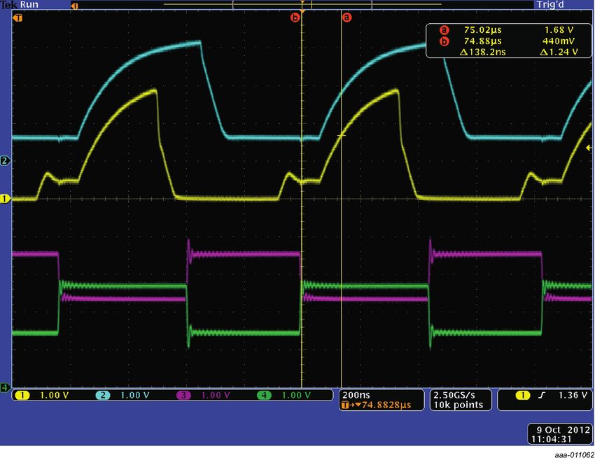
 Figure 11. Differential bus waveform

                                        9th clock pulse
                                         acknowledge

            SCL

                                                                                                            VOL of PCA9615 (from target)

            SDA

                                                                                                                                            002aah771
                                        VOL of controller

 Figure 12. Single-ended bus waveform (controller side of bus)

PCA9615                                 All information provided in this document is subject to legal disclaimers.                         © NXP B.V. 2021. All rights reserved.

Product data sheet                                 Rev. 2 — 16 September 2021
                                                                                                                                                                     15 / 30
NXP Semiconductors
                                                                                                                                    PCA9615
                                                                                                                         2
                            2-channel multipoint Fast-mode Plus differential I C-bus buffer with hot-swap logic

9         Limiting values
Table 4. Limiting values
In accordance with the Absolute Maximum Rating System (IEC 60134).
Symbol        Parameter                             Conditions                                                               Min        Max                Unit
VDD(B)        supply voltage port B                 differential bus; 3.0 V to 5.5 V                                         -0.5       +6                 V
VDD(A)        supply voltage port A                 single-ended bus; 2.3 V to 5.5 V                                         -0.5       +6                 V
VO(dif)       differential output voltage                                                                                    -0.5       +6                 V
                                                                          2
Vbus          bus voltage                           voltage on I C-bus A side, or enable (EN)                                -0.5       +6                 V
II/O          input/output current                  SDA, SCL, Dxxxx                                                          -          80                 mA
IDD(B)        supply current port B                                                                                          -          160                mA
Ptot          total power dissipation                                                                                        -          100                mW
Tstg          storage temperature                                                                                            -55        +125               °C
Tamb          ambient temperature                   operating in free air                                                    -40        +85                °C
Tj            junction temperature                                                                                           -          125                °C

PCA9615                                     All information provided in this document is subject to legal disclaimers.              © NXP B.V. 2021. All rights reserved.

Product data sheet                                     Rev. 2 — 16 September 2021
                                                                                                                                                              16 / 30
NXP Semiconductors
                                                                                                                                                PCA9615
                                                                                                                         2
                           2-channel multipoint Fast-mode Plus differential I C-bus buffer with hot-swap logic

10 Static characteristics
Table 5. Static characteristics
VDD(B) = 3.0 V to 5.5 V; VSS = 0 V; Tamb = -40 °C to +85 °C; unless otherwise specified.
Symbol     Parameter                     Conditions                                                                            Min       Typ        Max                   Unit
Supplies
VDD(B)     supply voltage port B         differential bus                                                                      3.0       -          5.5                   V
                                                                                                                         [1]
VDD(A)     supply voltage port A         single-ended bus                                                                      2.3       -          5.5                   V
IDD(VDDA) supply current on pin                                                                                                -         -          16                    μA
          VDD(A)
IDDH(B)    port B HIGH-level supply      both channels HIGH; VDD(B) = 5.5 V; SDAn                                              -         0.8        1.6                   mA
           current                       = SCLn = VDD(A) = 5.5 V
IDDL(B)    port B LOW-level supply       both channels LOW; VDD(B) = 5.5 V; SDA                                                -         1.1        1.8                   mA
           current                       and SCL = VSS; differential I/Os open
                                         driving termination; 2 channel                                                        -         70         91                    mA
Input and output SDA and SCL
VIH        HIGH-level input voltage                                                                                            0.7VDD(A) -          5.5                   V
VIL        LOW-level input voltage                                                                                             -0.5      -          +0.4                  V
VIK        input clamping voltage        II = -18 mA                                                                           -1.5      -          0                     V
ILI        input leakage current         VI = VDD(A)                                                                           -         -          ±2                    μA
IIL        LOW-level input current       SDA, SCL; VI = 0.2 V                                                                  -         -          12                    μA
VOL        LOW-level output voltage      IOL = 200 μA or 30 mA                                                                 0.47      0.52       0.6                   V
VOL-VIL    difference between LOW-       guaranteed by design                                                                  -         -          90                    mV
           level output and LOW-
           level input voltage
ILOH       HIGH-level output leakage VO = VDD(A)                                                                               -         -          ±2                    μA
           current
Cio        input/output capacitance      VI = VDD(A) or 0 V; disabled or VDD(A) = 0 V                                          -         7          10                    pF
Input and output DSDAP/DSDAM and DSCLP/DSCLM
Vcm        common-mode voltage                                                                                                 0         -          VDD(B)                V
ILI        input leakage current         VI = VDD(B)                                                                           -         -          ±40                   μA
IIL        LOW-level input current       VI = 0.2 V                                                                            -         -          ±40                   μA
RPU        pull-up resistance            internal pull-up resistor on DSCLM and                                                -         200        -                     kΩ
                                         DSDAM connected to VDD(B) rail
Rpd        pull-down resistance          internal pull-down resistor on DSCLP and                                              -         200        -                     kΩ
                                         DSDAP connected to VSS rail
Vth(dif)   differential receiver         0 V ≤ Vcm ≤ VDD(B)                                                                    -200      -          +200                  mV
           threshold voltage
VI(hys)    hysteresis of input voltage receiver; 0 V ≤ Vcm ≤ VDD(B)                                                            -         30         -                     mV
Vo(dif)(p-p) peak-to-peak differential   single-ended input LOW
             output voltage
                                             no load                                                                           -VDD(B)   -          -                     V
                                             RL = 54 Ω at VDD(B) = 5 V                                                         -5.0      -1.5       -1.0                  V

PCA9615                                     All information provided in this document is subject to legal disclaimers.                          © NXP B.V. 2021. All rights reserved.

Product data sheet                                     Rev. 2 — 16 September 2021
                                                                                                                                                                          17 / 30
NXP Semiconductors
                                                                                                                                                                  PCA9615
                                                                                                                                    2
                                   2-channel multipoint Fast-mode Plus differential I C-bus buffer with hot-swap logic

Table 5. Static characteristics...continued
VDD(B) = 3.0 V to 5.5 V; VSS = 0 V; Tamb = -40 °C to +85 °C; unless otherwise specified.
Symbol         Parameter                           Conditions                                                                           Min               Typ         Max                   Unit
Cio            input/output capacitance            VI = VDD(B) or 0 V; disabled or VDD(B) = 0 V                                         -                 7           10                    pF
Input EN
VIH            HIGH-level input voltage                                                                                                 0.7VDD(A) -                   5.5                   V
VIL            LOW-level input voltage                                                                                                  -0.5              -           +0.3VDD(A) V
ILI            input leakage current               VI = VDD(B)                                                                          -1                -           +1                    μA
IIL(EN)        LOW-level input current             VI = 0.2 V, EN; VDD(A) = 5.5 V                                                       -                 -20         -54                   μA
               on pin EN
Ci             input capacitance                   VI = VDD(A)                                                                          -                 6           10                    pF
RPU            pull-up resistance                  internal pull-up resistor connected to                                               -                 300         -                     kΩ
                                                   VDD(A) rail

[1]    LOW-level supply voltage.

11 Dynamic characteristics
Table 6. Dynamic characteristics
                                                                                     [1][2]
VDD = 2.7 V to 5.5 V; VSS = 0 V; Tamb = -40 °C to +85 °C; unless otherwise specified.
                                                                                                                                                                     [3]
Symbol          Parameter                                     Conditions                                                                           Min        Typ            Max            Unit
                                                                                                                                             [4]
tPLH            LOW to HIGH propagation delay single-ended side to differential side;                                                              -140       -120           -              ns
                                              Figure 15
tPLH2           LOW to HIGH propagation delay single-ended side to differential side;                                                              -          -              100            ns
                2                             Figure 15
                                                                                                                                             [5]
tPHL            HIGH to LOW propagation delay single-ended side to differential side;                                                              -          -              120            ns
                                              Figure 13
SRr             rising slew rate                              differential side; Figure 13                                                         -          -              1              V/ns
                                                                                                                                             [5]
SRf             falling slew rate                             differential side; Figure 13                                                         -          -              1              V/ns
                                                                                                                                             [6]
tPLH            LOW to HIGH propagation delay differential side to single-ended side;                                                              -          -              150            ns
                                              Figure 14
                                                                                                                                             [6]
tPHL            HIGH to LOW propagation delay differential side to single-ended side;                                                              -          -              150            ns
                                              Figure 14
SRf             falling slew rate                             single-ended side; Figure 14                                                         -          -              0.1            V/ns
                                                                                                                                             [7]
tdis            disable time                                  EN LOW to disable                                                                    -          -              200            ns

[1]    Times are specified with loads of 1.35 kΩ pull-up resistance and 50 pF load capacitance on the A side, and 50 Ω termination network resistance and 50
       pF load capacitance on the B side. Different load resistance and capacitance alters the RC time constant, thereby changing the propagation delay and
       transition times.
[2]    Pull-up voltages are VDD(A) on the A side and termination network on the B side.
[3]    Typical values were measured with VDD(A) = 3.3 V at Tamb = 25 °C, unless otherwise noted.
[4]    The tPLH delay data from B side to A side is measured at 0 V differential on the B side to 0.5VDD(A) on the A side.
[5]    Typical value measured with VDD(A) = 3.3 V at Tamb = 25 °C.
[6]    The proportional delay data from A side to B side is measured at 0.5VDD(A) on the A side to 0 V on the B side.
[7]    The enable pin (EN) should only change state when the global bus and the repeater port are in an idle state.

PCA9615                                                All information provided in this document is subject to legal disclaimers.                                 © NXP B.V. 2021. All rights reserved.

Product data sheet                                                Rev. 2 — 16 September 2021
                                                                                                                                                                                            18 / 30
NXP Semiconductors
                                                                                                                                                        PCA9615
                                                                                                                                   2
                                  2-channel multipoint Fast-mode Plus differential I C-bus buffer with hot-swap logic

                     11.1 AC waveforms
                                                            VDD(A)
          input     0.5VDD(A)           0.5VDD(A)                                                                                                                  0.3 V
                                                            0.1 V                                     input                                                        differential
                                                                                                                          0V                     0V                voltage
                   tPHL                 tPLH
                                                                                                                                                                   - 0.3 V
                                                                                                                        tPHL                     tPLH
                                                                 0.3 V
                  80 %                           80 %            differential
     output               0V             0V                                                                                                                            VDD(A)
                                                                 voltage                                            80 %                                80 %
                          20 %        20 %
                                                                 - 2.5 V                            output                        0.5VDD(A) 0.5VDD(A)
                           tTHL                     tTLH                                                                           20 %        20 %
                                                            002aag416                                                               tTHL                  tTLH
 VDD(A) = 3.0 V.                                                                                                                                                 002aag417

 SRf = 0.6 × (Vhigh - Vlow) / tTHL                                                         VDD(A) = 3.0 V.
 SRr = 0.6 × (Vhigh - Vlow) / tTLH                                                         SRf = 0.6 ´ VDD(A) / tTHL
 Figure 13. Propagation delay and transition times;                                        Figure 14. Propagation delay and transition times;
 single-ended side to differential side                                                    differential side to single-ended side
                                                                               tPLH
                                                                                           0.5VDD(A)
                                                   input
                                               SDA, SCL
                                                                    0.5 V

                                                                                                                                    0.3 V
                                               output
                                                                                0V
                                        DSCLP/DSCLM,
                                        DSDAP/DSDAM
                                                                                                                                    - 2.5 V
                                                                   tPLH2
                                                                                                                                  002aag418

 Figure 15. Propagation delay

PCA9615                                              All information provided in this document is subject to legal disclaimers.                         © NXP B.V. 2021. All rights reserved.

Product data sheet                                              Rev. 2 — 16 September 2021
                                                                                                                                                                                  19 / 30
NXP Semiconductors
                                                                                                                                            PCA9615
                                                                                                                  2
                     2-channel multipoint Fast-mode Plus differential I C-bus buffer with hot-swap logic

12 Test information
                                                                                                                           VDD(B)
                                                                                           VDD(A)
                                                                                                        VDD(B)                 300
                                                                                                  VDD(A)
                                                                                     VI                                                VO
                                PULSE                     I2C-BUS                                                 P                         DIFFERENTIAL
                                                                                                        DUT                    60              PROBE
                              GENERATOR                LEVEL SHIFTER                                              M

                                                  RT
                                                                                                                               300

                                                                                                                                                   002aag419

                     RL = load resistor; 1.35 kΩ on single-ended side.
                     RT = termination resistance should be equal to Zo of pulse generators.
                     Figure 16. Test circuit for differential outputs

                                                                                                                             VDD(A)
                                                                                                            VDD(A)
                                                                                                  VDD(B)
                                                                                                                                RL
                                                                                                                      VO
                                                                                                    P
                                                          DIFFERENTIAL                     RT         DUT
                                                                                                    M

                                                                                                                                CL

                                                                                                                           002aag420

                     RL = load resistor; 1.35 kΩ on single-ended side.
                     CL = load capacitance includes jig and probe capacitance; 50 pF.
                     RT = termination resistance should be equal to Zo of pulse generators.
                     Figure 17. Test circuit for open-drain output

PCA9615                              All information provided in this document is subject to legal disclaimers.                              © NXP B.V. 2021. All rights reserved.

Product data sheet                              Rev. 2 — 16 September 2021
                                                                                                                                                                       20 / 30
NXP Semiconductors
                                                                                                                                                                            PCA9615
                                                                                                                                                  2
                                   2-channel multipoint Fast-mode Plus differential I C-bus buffer with hot-swap logic

13 Package outline

  TSSOP10: plastic thin shrink small outline package; 10 leads; body width 3 mm                                                                                                             SOT552-1

                                                 D                                                                                 E                       A
                                                                                                                                                                  X

                                                                                                 c

                                    y                                                                                             HE                                    v M A

                                            Z

                               10                              6

                                                                                                      A2                                                   (A3)         A
                                                                                                             A1
                                     pin 1 index

                                                                                                                                                                   θ
                                                                                                                                                    Lp
                                                                                                                                                L
                               1                               5
                                                                                                                                       detail X
                                        e                                 w M
                                                          bp

                                                                        0                             2.5                         5 mm
                                                                                                     scale

     DIMENSIONS (mm are the original dimensions)
                  A                                                          D (1)       E (2)
          UNIT          A1      A2              A3   bp             c                                  e          HE        L          Lp           v      w      y         Z (1)      θ
                 max.
                        0.15   0.95                  0.30          0.23       3.1        3.1                      5.0                  0.7                                  0.67       6°
          mm     1.1                        0.25                                                      0.5                 0.95                    0.1     0.1     0.1
                        0.05   0.80                  0.15          0.15       2.9        2.9                      4.8                  0.4                                  0.34       0°

     Notes
     1. Plastic or metal protrusions of 0.15 mm maximum per side are not included.
     2. Plastic or metal protrusions of 0.25 mm maximum per side are not included.

            OUTLINE                                                         REFERENCES                                                                    EUROPEAN
                                                                                                                                                                                    ISSUE DATE
            VERSION                  IEC                           JEDEC                          JEITA                                                  PROJECTION

                                                                                                                                                                                     99-07-29
             SOT552-1
                                                                                                                                                                                     03-02-18

 Figure 18. Package outline SOT552-1 (TSSOP10)

PCA9615                                                            All information provided in this document is subject to legal disclaimers.                                 © NXP B.V. 2021. All rights reserved.

Product data sheet                                                            Rev. 2 — 16 September 2021
                                                                                                                                                                                                        21 / 30
NXP Semiconductors
                                                                                                                       PCA9615
                                                                                                                   2
                      2-channel multipoint Fast-mode Plus differential I C-bus buffer with hot-swap logic

14 Soldering of SMD packages
                     This text provides a very brief insight into a complex technology. A more in-depth account
                     of soldering ICs can be found in Application Note AN10365 "Surface mount reflow
                     soldering description."

                14.1 Introduction to soldering
                     Soldering is one of the most common methods through which packages are attached
                     to Printed Circuit Boards (PCBs), to form electrical circuits. The soldered joint provides
                     both the mechanical and the electrical connection. There is no single soldering method
                     that is ideal for all IC packages. Wave soldering is often preferred when through-hole
                     and Surface Mount Devices (SMDs) are mixed on one printed wiring board; however, it is
                     not suitable for fine pitch SMDs. Reflow soldering is ideal for the small pitches and high
                     densities that come with increased miniaturization.

                14.2 Wave and reflow soldering
                     Wave soldering is a joining technology in which the joints are made by solder coming
                     from a standing wave of liquid solder. The wave soldering process is suitable for the
                     following:
                     • Through-hole components
                     • Leaded or leadless SMDs, which are glued to the surface of the printed circuit board
                     Not all SMDs can be wave soldered. Packages with solder balls, and some leadless
                     packages which have solder lands underneath the body, cannot be wave soldered. Also,
                     leaded SMDs with leads having a pitch smaller than ~0.6 mm cannot be wave soldered,
                     due to an increased probability of bridging.
                     The reflow soldering process involves applying solder paste to a board, followed by
                     component placement and exposure to a temperature profile. Leaded packages,
                     packages with solder balls, and leadless packages are all reflow solderable.
                     Key characteristics in both wave and reflow soldering are:
                     •   Board specifications, including the board finish, solder masks and vias
                     •   Package footprints, including solder thieves and orientation
                     •   The moisture sensitivity level of the packages
                     •   Package placement
                     •   Inspection and repair
                     •   Lead-free soldering versus SnPb soldering

                14.3 Wave soldering
                     Key characteristics in wave soldering are:
                     • Process issues, such as application of adhesive and flux, clinching of leads, board
                       transport, the solder wave parameters, and the time during which components are
                       exposed to the wave
                     • Solder bath specifications, including temperature and impurities

PCA9615                               All information provided in this document is subject to legal disclaimers.       © NXP B.V. 2021. All rights reserved.

Product data sheet                               Rev. 2 — 16 September 2021
                                                                                                                                                 22 / 30
NXP Semiconductors
                                                                                                                              PCA9615
                                                                                                                  2
                     2-channel multipoint Fast-mode Plus differential I C-bus buffer with hot-swap logic

                14.4 Reflow soldering
                     Key characteristics in reflow soldering are:
                     • Lead-free versus SnPb soldering; note that a lead-free reflow process usually leads
                       to higher minimum peak temperatures (see Figure 19) than a SnPb process, thus
                       reducing the process window
                     • Solder paste printing issues including smearing, release, and adjusting the process
                       window for a mix of large and small components on one board
                     • Reflow temperature profile; this profile includes preheat, reflow (in which the board
                       is heated to the peak temperature) and cooling down. It is imperative that the peak
                       temperature is high enough for the solder to make reliable solder joints (a solder
                       paste characteristic). In addition, the peak temperature must be low enough that the
                       packages and/or boards are not damaged. The peak temperature of the package
                       depends on package thickness and volume and is classified in accordance with Table 7
                       and Table 8

                     Table 7. SnPb eutectic process (from J-STD-020D)
                     Package thickness (mm)                  Package reflow temperature (°C)
                                                                                      3
                                                             Volume (mm )
                                                             < 350                                                    ≥ 350
                     < 2.5                                   235                                                      220
                     ≥ 2.5                                   220                                                      220

                     Table 8. Lead-free process (from J-STD-020D)
                     Package thickness (mm)                  Package reflow temperature (°C)
                                                                                      3
                                                             Volume (mm )
                                                             < 350                                      350 to 2 000          > 2 000
                     < 1.6                                   260                                        260                   260
                     1.6 to 2.5                              260                                        250                   245
                     > 2.5                                   250                                        245                   245

                     Moisture sensitivity precautions, as indicated on the packing, must be respected at all
                     times.
                     Studies have shown that small packages reach higher temperatures during reflow
                     soldering, see Figure 19.

PCA9615                              All information provided in this document is subject to legal disclaimers.                © NXP B.V. 2021. All rights reserved.

Product data sheet                              Rev. 2 — 16 September 2021
                                                                                                                                                         23 / 30
NXP Semiconductors
                                                                                                                                PCA9615
                                                                                                                   2
                     2-channel multipoint Fast-mode Plus differential I C-bus buffer with hot-swap logic

                                                                maximum peak temperature
                             temperature                         = MSL limit, damage level

                                                              minimum peak temperature
                                                        = minimum soldering temperature

                                                                                                                          peak
                                                                                                                       temperature

                                                                                                                                             time
                                                                                                                                     001aac844

                     MSL: Moisture Sensitivity Level
                     Figure 19. Temperature profiles for large and small components

                     For further information on temperature profiles, refer to Application Note AN10365
                     "Surface mount reflow soldering description".

PCA9615                               All information provided in this document is subject to legal disclaimers.                 © NXP B.V. 2021. All rights reserved.

Product data sheet                               Rev. 2 — 16 September 2021
                                                                                                                                                           24 / 30
NXP Semiconductors
                                                                                                                                PCA9615
                                                                                                                            2
                               2-channel multipoint Fast-mode Plus differential I C-bus buffer with hot-swap logic

15 Soldering: PCB footprints
 Footprint information for reflow soldering of TSSOP10 package                                                                                 SOT552 -1

                                                                                 Hx

                                                                 P1

                                       Hy   Gy

                       solder land

                       occupied area

    Dimensions in mm

          Gy    Hy     Hx      P1
                                                       11-04-19
          3.1   5.0    3.1     0.5      Issue date
                                                       13-05-02                                                                                sot552-1_fr

 Figure 20. PCB footprint for SOT552-1 (TSSOP10); reflow soldering

PCA9615                                        All information provided in this document is subject to legal disclaimers.       © NXP B.V. 2021. All rights reserved.

Product data sheet                                        Rev. 2 — 16 September 2021
                                                                                                                                                          25 / 30
NXP Semiconductors
                                                                                                                             PCA9615
                                                                                                                    2
                       2-channel multipoint Fast-mode Plus differential I C-bus buffer with hot-swap logic

16 Abbreviations
                       Table 9. Abbreviations
                       Acronym            Description
                       CDM                Charged-Device Model
                            2
                       dI C-bus           differential Inter-Integrated Circuit bus
                       ESD                ElectroStatic Discharge
                       HBM                Human Body Model
                        2
                       I C-bus            Inter-Integrated Circuit bus
                       I/O                Input/Output
                       LED                Light Emitting Diode
                       SMBus              System Management Bus

17 Revision history
Table 10. Revision history
Document ID          Release date         Data sheet status                                 Change notice               Supersedes
PCA9615 v.2          20210916             Product data sheet                                PCN 202104008A              PCA9615 v.1.1
Modifications        • The format of this data sheet has been redesigned to comply with the new identity guidelines
                       of NXP Semiconductors, N.V. Legal texts have been adapted to the new company name where
                       appropriate.
                     • Global changes, revised as follows:
                       – "Master" or "master": revised to "Controller" or "controller" to conform with NXP inclusive
                         language guidelines.
                       – "Slave" or "slave": revised to "Target" or "target" to conform with NXP inclusive language
                         guidelines.
                     • Section 4.1, Table 2, added footnote on PCA9615DPJ and inserted new part number
                       PCA9615DPZ.
PCA9615 v.1.1        20160510             Product data sheet                                -                           PCA9615 v.1
PCA9615 v.1          20140502             Product data sheet                                -                           -

PCA9615                                All information provided in this document is subject to legal disclaimers.             © NXP B.V. 2021. All rights reserved.

Product data sheet                                Rev. 2 — 16 September 2021
                                                                                                                                                        26 / 30
NXP Semiconductors
                                                                                                                                                  PCA9615
                                                                                                                                    2
                                  2-channel multipoint Fast-mode Plus differential I C-bus buffer with hot-swap logic

18 Legal information

18.1 Data sheet status
                    [1][2]                                       [3]
 Document status                               Product status                                Definition
 Objective [short] data sheet                  Development                                   This document contains data from the objective specification for product
                                                                                             development.
 Preliminary [short] data sheet                Qualification                                 This document contains data from the preliminary specification.
 Product [short] data sheet                    Production                                    This document contains the product specification.

[1]   Please consult the most recently issued document before initiating or completing a design.
[2]   The term 'short data sheet' is explained in section "Definitions".
[3]   The product status of device(s) described in this document may have changed since this document was published and may differ in case of multiple
      devices. The latest product status information is available on the Internet at URL http://www.nxp.com.

                                                                                                notice. This document supersedes and replaces all information supplied prior
                                                                                                to the publication hereof.
18.2 Definitions
                                                                                                Suitability for use — NXP Semiconductors products are not designed,
Draft — A draft status on a document indicates that the content is still                        authorized or warranted to be suitable for use in life support, life-critical or
under internal review and subject to formal approval, which may result                          safety-critical systems or equipment, nor in applications where failure or
in modifications or additions. NXP Semiconductors does not give any                             malfunction of an NXP Semiconductors product can reasonably be expected
representations or warranties as to the accuracy or completeness of                             to result in personal injury, death or severe property or environmental
information included in a draft version of a document and shall have no                         damage. NXP Semiconductors and its suppliers accept no liability for
liability for the consequences of use of such information.                                      inclusion and/or use of NXP Semiconductors products in such equipment or
                                                                                                applications and therefore such inclusion and/or use is at the customer’s own
Short data sheet — A short data sheet is an extract from a full data sheet                      risk.
with the same product type number(s) and title. A short data sheet is
intended for quick reference only and should not be relied upon to contain                      Applications — Applications that are described herein for any of these
detailed and full information. For detailed and full information see the                        products are for illustrative purposes only. NXP Semiconductors makes
relevant full data sheet, which is available on request via the local NXP                       no representation or warranty that such applications will be suitable
Semiconductors sales office. In case of any inconsistency or conflict with the                  for the specified use without further testing or modification. Customers
short data sheet, the full data sheet shall prevail.                                            are responsible for the design and operation of their applications and
                                                                                                products using NXP Semiconductors products, and NXP Semiconductors
Product specification — The information and data provided in a Product                          accepts no liability for any assistance with applications or customer product
data sheet shall define the specification of the product as agreed between                      design. It is customer’s sole responsibility to determine whether the NXP
NXP Semiconductors and its customer, unless NXP Semiconductors and                              Semiconductors product is suitable and fit for the customer’s applications
customer have explicitly agreed otherwise in writing. In no event however,                      and products planned, as well as for the planned application and use of
shall an agreement be valid in which the NXP Semiconductors product                             customer’s third party customer(s). Customers should provide appropriate
is deemed to offer functions and qualities beyond those described in the                        design and operating safeguards to minimize the risks associated with
Product data sheet.                                                                             their applications and products. NXP Semiconductors does not accept any
                                                                                                liability related to any default, damage, costs or problem which is based
                                                                                                on any weakness or default in the customer’s applications or products, or
                                                                                                the application or use by customer’s third party customer(s). Customer is
18.3 Disclaimers                                                                                responsible for doing all necessary testing for the customer’s applications
                                                                                                and products using NXP Semiconductors products in order to avoid a
                                                                                                default of the applications and the products or of the application or use by
Limited warranty and liability — Information in this document is believed                       customer’s third party customer(s). NXP does not accept any liability in this
to be accurate and reliable. However, NXP Semiconductors does not                               respect.
give any representations or warranties, expressed or implied, as to the
accuracy or completeness of such information and shall have no liability                        Limiting values — Stress above one or more limiting values (as defined in
for the consequences of use of such information. NXP Semiconductors                             the Absolute Maximum Ratings System of IEC 60134) will cause permanent
takes no responsibility for the content in this document if provided by an                      damage to the device. Limiting values are stress ratings only and (proper)
information source outside of NXP Semiconductors. In no event shall NXP                         operation of the device at these or any other conditions above those
Semiconductors be liable for any indirect, incidental, punitive, special or                     given in the Recommended operating conditions section (if present) or the
consequential damages (including - without limitation - lost profits, lost                      Characteristics sections of this document is not warranted. Constant or
savings, business interruption, costs related to the removal or replacement                     repeated exposure to limiting values will permanently and irreversibly affect
of any products or rework charges) whether or not such damages are based                        the quality and reliability of the device.
on tort (including negligence), warranty, breach of contract or any other
legal theory. Notwithstanding any damages that customer might incur for
                                                                                                Terms and conditions of commercial sale — NXP Semiconductors
any reason whatsoever, NXP Semiconductors’ aggregate and cumulative
                                                                                                products are sold subject to the general terms and conditions of commercial
liability towards customer for the products described herein shall be limited
                                                                                                sale, as published at http://www.nxp.com/profile/terms, unless otherwise
in accordance with the Terms and conditions of commercial sale of NXP
                                                                                                agreed in a valid written individual agreement. In case an individual
Semiconductors.
                                                                                                agreement is concluded only the terms and conditions of the respective
                                                                                                agreement shall apply. NXP Semiconductors hereby expressly objects to
Right to make changes — NXP Semiconductors reserves the right to                                applying the customer’s general terms and conditions with regard to the
make changes to information published in this document, including without                       purchase of NXP Semiconductors products by customer.
limitation specifications and product descriptions, at any time and without

PCA9615                                                All information provided in this document is subject to legal disclaimers.                   © NXP B.V. 2021. All rights reserved.

Product data sheet                                                Rev. 2 — 16 September 2021
                                                                                                                                                                              27 / 30
NXP Semiconductors
                                                                                                                                                 PCA9615
                                                                                                                                    2
                                 2-channel multipoint Fast-mode Plus differential I C-bus buffer with hot-swap logic

No offer to sell or license — Nothing in this document may be interpreted                       Security — Customer understands that all NXP products may be subject
or construed as an offer to sell products that is open for acceptance or                        to unidentified or documented vulnerabilities. Customer is responsible
the grant, conveyance or implication of any license under any copyrights,                       for the design and operation of its applications and products throughout
patents or other industrial or intellectual property rights.                                    their lifecycles to reduce the effect of these vulnerabilities on customer’s
                                                                                                applications and products. Customer’s responsibility also extends to other
Export control — This document as well as the item(s) described herein                          open and/or proprietary technologies supported by NXP products for use
may be subject to export control regulations. Export might require a prior                      in customer’s applications. NXP accepts no liability for any vulnerability.
authorization from competent authorities.                                                       Customer should regularly check security updates from NXP and follow up
                                                                                                appropriately. Customer shall select products with security features that best
Non-automotive qualified products — Unless this data sheet expressly                            meet rules, regulations, and standards of the intended application and make
states that this specific NXP Semiconductors product is automotive qualified,                   the ultimate design decisions regarding its products and is solely responsible
the product is not suitable for automotive use. It is neither qualified nor                     for compliance with all legal, regulatory, and security related requirements
tested in accordance with automotive testing or application requirements.                       concerning its products, regardless of any information or support that may
NXP Semiconductors accepts no liability for inclusion and/or use of non-                        be provided by NXP. NXP has a Product Security Incident Response Team
automotive qualified products in automotive equipment or applications. In                       (PSIRT) (reachable at PSIRT@nxp.com) that manages the investigation,
the event that customer uses the product for design-in and use in automotive                    reporting, and solution release to security vulnerabilities of NXP products.
applications to automotive specifications and standards, customer (a) shall
use the product without NXP Semiconductors’ warranty of the product for
such automotive applications, use and specifications, and (b) whenever
customer uses the product for automotive applications beyond NXP                                18.4 Trademarks
Semiconductors’ specifications such use shall be solely at customer’s own
risk, and (c) customer fully indemnifies NXP Semiconductors for any liability,                  Notice: All referenced brands, product names, service names and
damages or failed product claims resulting from customer design and use                         trademarks are the property of their respective owners.
of the product for automotive applications beyond NXP Semiconductors’
standard warranty and NXP Semiconductors’ product specifications.                                2
                                                                                                I C-bus — logo is a trademark of NXP B.V.
Translations — A non-English (translated) version of a document is for                          NXP — wordmark and logo are trademarks of NXP B.V.
reference only. The English version shall prevail in case of any discrepancy
between the translated and English versions.

PCA9615                                                All information provided in this document is subject to legal disclaimers.                  © NXP B.V. 2021. All rights reserved.

Product data sheet                                                Rev. 2 — 16 September 2021
                                                                                                                                                                             28 / 30
NXP Semiconductors
                                                                                                                                                           PCA9615
                                                                                                                                   2
                               2-channel multipoint Fast-mode Plus differential I C-bus buffer with hot-swap logic

Tables
Tab. 1.    Ordering information ..........................................3                    Tab. 6.             Dynamic characteristics .................................. 18
Tab. 2.    Ordering options ................................................3                  Tab. 7.             SnPb eutectic process (from J-STD-020D) ..... 23
Tab. 3.    Pin description ...................................................5                Tab. 8.             Lead-free process (from J-STD-020D) ............ 23
Tab. 4.    Limiting values ................................................ 16                 Tab. 9.             Abbreviations ...................................................26
Tab. 5.    Static characteristics ....................................... 17                   Tab. 10.            Revision history ...............................................26

Figures
Fig. 1.    SMBus/I2C-bus translation to dI2C-bus and                                           Fig. 12.            Single-ended bus waveform (controller side
           back to SMBus/I2C-bus .................................... 2                                            of bus) ............................................................. 15
Fig. 2.    Block diagram (level 0) ..................................... 4                     Fig. 13.            Propagation delay and transition times;
Fig. 3.    Differential output driver simplified circuit .......... 4                                              single-ended side to differential side ............... 19
Fig. 4.    Pin configuration for TSSOP10 ......................... 5                           Fig. 14.            Propagation delay and transition times;
Fig. 5.    dI2C-bus terminations ....................................... 7                                         differential side to single-ended side ............... 19
Fig. 6.    Hot swap related timings ...................................8                       Fig. 15.            Propagation delay ........................................... 19
Fig. 7.    Typical application for PCA9615 ..................... 11                            Fig. 16.            Test circuit for differential outputs ....................20
Fig. 8.    PCA9615 application diagram; VDD and                                                Fig. 17.            Test circuit for open-drain output .....................20
           VSS are routed through the cable ...................12                              Fig. 18.            Package outline SOT552-1 (TSSOP10) ..........21
Fig. 9.    PCA9615 application diagram; VDD and                                                Fig. 19.            Temperature profiles for large and small
           VSS are not routed through the cable ............. 13                                                   components ..................................................... 24
Fig. 10.   Hot swap application ....................................... 14                     Fig. 20.            PCB footprint for SOT552-1 (TSSOP10);
Fig. 11.   Differential bus waveform ................................15                                            reflow soldering ............................................... 25

PCA9615                                               All information provided in this document is subject to legal disclaimers.                            © NXP B.V. 2021. All rights reserved.

Product data sheet                                               Rev. 2 — 16 September 2021
                                                                                                                                                                                      29 / 30
You can also read