ARCHIMATE COOKBOOK PATTERNS & EXAMPLES
←
→
Page content transcription
If your browser does not render page correctly, please read the page content below
ArchiMate Cookbook
Patterns & Examples

Document information
Version                1.0
Created                2019-07-20
Modified               2020-10-16
Author                 Eero Hosiaisluoma (EHo)
ArchiMate Cookbook
Patterns & Examples

Table Of Contents

1. Introduction ................................................................................................................................................................4
    1.1 Purpose And Scope ............................................................................................................................................4
    1.2 References ..........................................................................................................................................................4
2. ArchiMate Diagram Types .........................................................................................................................................5
    2.1 Motivation View (Goals View) .............................................................................................................................5
        2.1.1 Motivation View - Example ..........................................................................................................................6
        2.1.2 Risk Analysis View.......................................................................................................................................7
    2.2 Business Model View ..........................................................................................................................................8
        2.2.1 Business Model Canvas (BMC)...................................................................................................................8
        2.2.2 SWOT Analysis View ...................................................................................................................................8
        2.2.3 Value Stream View ......................................................................................................................................9
        2.2.4 Strategy & Capability View ........................................................................................................................11
        2.2.5 Implementation Roadmap View.................................................................................................................14
    2.3 Layered View ....................................................................................................................................................16
        2.3.1 Layered View - Business- and Application Layers Example .....................................................................17
        2.3.2 Layered View - Business Layer .................................................................................................................17
        2.3.3 Layered View - Customer Service Journey ...............................................................................................18
        2.3.4 Layered View - Swimline Process View ....................................................................................................19
        2.3.5 Layered View - Service Design View ........................................................................................................20
        2.3.6 Layered View - Service Blueprint ..............................................................................................................21
    2.4 Interaction View (Co-operation View) ...............................................................................................................21
        2.4.1 Actor Interaction (Co-operation) View .......................................................................................................22
        2.4.2 Process Interaction (Co-operation) View ...................................................................................................22
        2.4.3 Application Interaction (Co-operation) View ..............................................................................................22
    2.5 Business Process View .....................................................................................................................................23
        2.5.1 Business Process Functional Decomposition View ..................................................................................23
    2.6 Conceptual Data Model View............................................................................................................................24
    2.7 Data Model View ...............................................................................................................................................25
    2.8 Technology Platform View (Infrastructure View) ..............................................................................................25
    2.9 Application Structure View (Solution Architecture View) ..................................................................................26
        2.9.1 Application Design Pattern (Basic Model) .................................................................................................26
        2.9.2 Application Logical Structure View (Application Structure / Internal Structure) ........................................27
        2.9.3 Component Model (CM) ............................................................................................................................28
        2.9.4 Database....................................................................................................................................................30
        2.9.5 Application Integrations .............................................................................................................................32
        2.9.6 Sequence Diagrams ..................................................................................................................................32
        2.9.7 Application Integration Patterns.................................................................................................................34
        2.9.8 Use Case View ..........................................................................................................................................35
3. ArchiMate-Elements (subset) ..................................................................................................................................37
    3.1 ArchiMate Motivation -Elements .......................................................................................................................38
    3.2 ArchiMate Strategy -Elements ..........................................................................................................................39

                                                                           Eero Hosiaisluoma ©
                                                                                                                                                                               2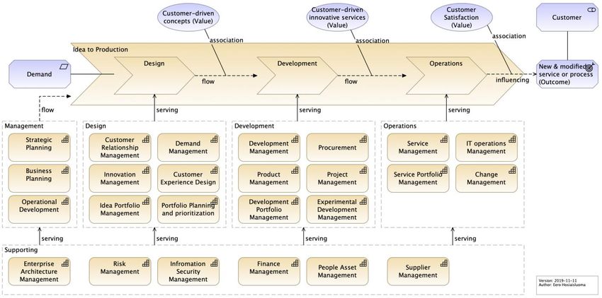
ArchiMate Cookbook
Patterns & Examples

    3.3 ArchiMate Business Layer -Elements ...............................................................................................................40
    3.4 ArchiMate Application Layer -Elements ............................................................................................................41
    3.5 ArchiMate Technology Layer -Elements ...........................................................................................................42
4. ArchiMate Relationships ..........................................................................................................................................43
5. Metamodel ...............................................................................................................................................................45
    5.1 Metamodel - Core .............................................................................................................................................45
    5.2 Metamodel - Full ...............................................................................................................................................46
6. Diagram Types ........................................................................................................................................................47
    6.1 Basic Views .......................................................................................................................................................48
    6.2 Business Model Views ......................................................................................................................................48
    6.3 Customer Views ................................................................................................................................................48
    6.4 Maps..................................................................................................................................................................48
    6.5 Solution Architecture Views ..............................................................................................................................49
7. Frameworks, Methods & Tools................................................................................................................................50
    7.1 Lean EA Framework (LEAF) .............................................................................................................................50
    7.2 Lean EA Development (LEAD) .........................................................................................................................51
    7.3 Goal-Driven Approach (GDA) ...........................................................................................................................52
    7.4 Service-Driven Approach (SDA) .......................................................................................................................53
    7.5 ArchiMate 1-2-3 .................................................................................................................................................55
    7.6 EA Content Frameworks ...................................................................................................................................56
        7.6.1 Layered Framework ...................................................................................................................................56
        7.6.2 Aspect-Oriented Framework ......................................................................................................................56
        7.6.3 Views & Maps Framework .........................................................................................................................56
    7.7 SIPOC (Suppliers, Inputs, Process, Outputs, Customers) ...............................................................................57
8. Appendixes ..............................................................................................................................................................58
    8.1 Appendix 1: Cloud Service Models ...................................................................................................................58
    8.2 Appendix 2: Modelling Tips & Tricks + Extra Patterns .....................................................................................58
        8.2.1 Line Width And Color .................................................................................................................................58
        8.2.2 Legend .......................................................................................................................................................59
        8.2.3 Grouping ....................................................................................................................................................59
        8.2.4 Abstracting Elements .................................................................................................................................59
        8.2.5 Enterprise Application Integration (EAI) patterns ......................................................................................60
        8.2.6 Information Resource ................................................................................................................................61
        8.2.7 API (Application Programming Interface) ..................................................................................................62

                                                                          Eero Hosiaisluoma ©
                                                                                                                                                                              3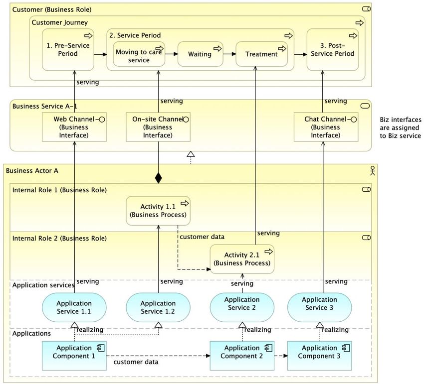
ArchiMate Cookbook
Patterns & Examples

1. Introduction
1.1 Purpose And Scope
This document covers ArchiMate -patterns and examples, those of which can be used for modelling concepts and
solutions related to the development work of an organization.
Almost all the business relevant behavioral and structural elements of an organization can be modelled with the
ArchiMate. ArchiMate is a comprehensive and powerful notation, with a wide range of elements and relationships.
However, only a subset of ArchiMate-elements and only a small set of diagram types are enough for most of the
modelling purposes (80% of the cases).
This document introduces the most useful diagram types and related ArchiMate-elements. This subset of
ArchiMate-elements is grouped into the layers of ArchiMate Framework (figure below).

Figure 1: ArchiMate Framework.
The diagrams in this document are modelled according to ArchiMate specification [1]. More ArchiMate -examples
can be found from the blog [2]. This document is updated continuously, more interesting topics are to be added,
and existing content is to be updated according to new information. This document can be freely used and shared.

1.2 References
[1] ArchiMate 3.1, Open Group, 2019. https://pubs.opengroup.org/architecture/archimate3-doc/
[2] Enterprise Architecture at Work, 4th Edition, Marc Lankhorst et al., Springer, 2017.
[3] Mastering ArchiMate, Edition III, Gerben Wierda, 2017.
[4] Lean Enterprise Architecture Method For Value Chain Based Development In Public Sector, Hosiaisluoma et
    al, 2018. https://www.hosiaisluoma.fi/blog/lean-enterprise-architecture-method-for-value-chain-based-
    development-in-public-sector/
[5] “ArchiMate Examples” blog, Eero Hosiaisluoma. https://www.hosiaisluoma.fi/blog/archimate-examples/
[6] “Holistic Enterprise Development” blog, Eero Hosiaisluoma https://www.hosiaisluoma.fi/blog/
[7] “ArchiMate Cookbook” blog, Eero Hosiaisluoma https://www.hosiaisluoma.fi/blog/archimate-cookbook/
[8] Value analysis with Value Stream and Capability modeling, Christine Dessus, 2019,
    https://www.slideshare.net/chdessus/value-analysis-with-value-stream-and-capability-modeling

                                                  Eero Hosiaisluoma ©
                                                                                                                   4
ArchiMate Cookbook
Patterns & Examples

2. ArchiMate Diagram Types
2.1 Motivation View (Goals View)

Figure 2: Motivation View - Design Pattern.
A Motivation View (a.k.a. Goals View) can be used for to depict why a demand is meaningful: WHY this change is
needed. With the Motivation View it is possible to model crucial drivers and root causes behind the demand, actual
goals and related outcomes, as well as concrete requirements for further development. The Motivation View
answers the questions to WHOM, WHY and WHAT. Whenever appropriate, a Value can be associated with the
Motivation View, if it is important to illustrate the concrete benefits of the demand (development target).
This diagram type is modelled with ArchiMate Motivation- and Strategy -elements.

                                                 Eero Hosiaisluoma ©
                                                                                                                 5
ArchiMate Cookbook
Patterns & Examples

2.1.1 Motivation View - Example

Figure 3: Motivation View - Example.
The Motivation View can be applied to many kinds of purposes, such as to depict a strategy of the whole
organization or to define the business case or requirements of a single development target.
ArchiMate Motivation- and Strategy -elements are quite self-descriptive when illustrated within the titled groups (as
shown in the figure above). Diverse stakeholder groups (managers, process- and software developers etc.) can
read the Motivation View without deep knowledge of ArchiMate. As a result of this, the Motivation View is very
multipurpose diagram type. It would be important and valuable to create a Motivation View for each and every
demand for change - before any (“build or buy”) actions are to be taken.

                                                  Eero Hosiaisluoma ©
                                                                                                                    6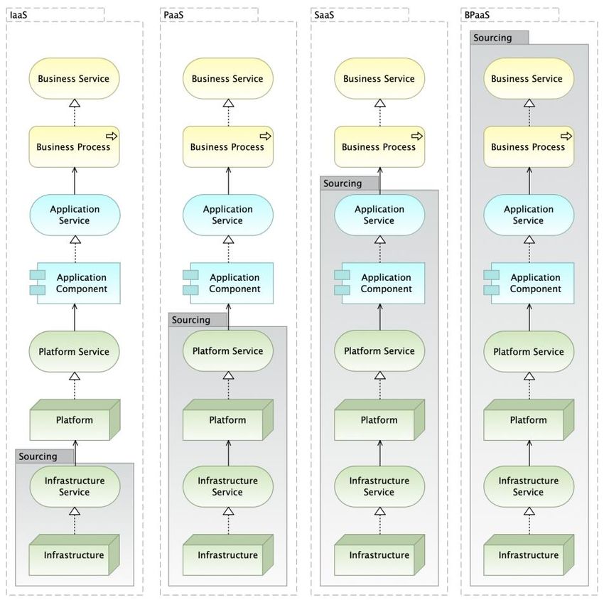
ArchiMate Cookbook
Patterns & Examples

2.1.2 Risk Analysis View

Figure 4: Risk and Security View - Pattern.
Risk and Security View. Mapping of Risk and Security Concepts to the ArchiMate. Security and data protection
matters are part of the risk management. This modelling approach covers them both.
This diagram type is modelled with ArchiMate Motivation -elements.
References:
   •   How to Model Enterprise Risk Management and Security with the ArchiMate® Language, Open Group,
       DocumentNo: W172, 2017.
   •   Modeling Enterprise Risk Management and Security with the ArchiMate® Language, Open Group, 2015.

                                                Eero Hosiaisluoma ©
                                                                                                               7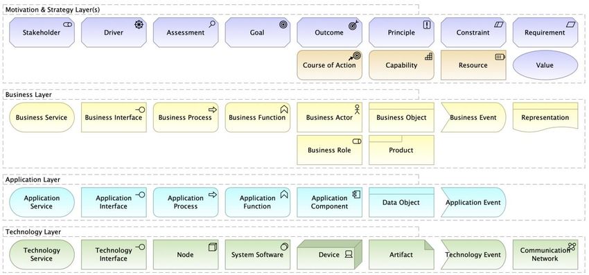
ArchiMate Cookbook
Patterns & Examples

2.2 Business Model View
2.2.1 Business Model Canvas (BMC)

Figure 5: Business Model - Business Model Canvas (BMC).
A Business Model Canvas (BMC) -diagram can be used for modelling a business model or a business case.
This diagram type is modelled primarily with ArchiMate Business Layer -elements together with certain Motivation-
and Strategy -elements.

2.2.2 SWOT Analysis View

Figure 6: SWOT Analysis - Design Pattern.
A development target can be analyzed and depicted with the SWOT View -diagram. (SWOT stands for Strengths,
Weaknesses, Opportunities and Threats.) This diagram type is modelled with ArchiMate Assessments -elements.

                                                Eero Hosiaisluoma ©
                                                                                                                    8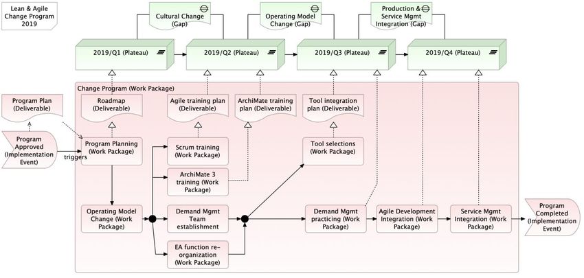
ArchiMate Cookbook
Patterns & Examples

2.2.3 Value Stream View

Figure 7: Value Stream - Design Pattern.
A Value Stream diagram defines e.g. how value is created for the customers according to the Business Model. In
addition, value stream modelling can be used to depict how the business capabilities are connected to the value
stream. This makes it visible what is the role and meaning of each capability (and related resources), and what is
the actual value-add of each capability in the overall end2end value creation stream (process). As such, the value
stream description (with capability connections) visualizes both the beneficial and unproductive capabilities, when
measured with pure value-creation factors. How an organization creates value for the customers, and with what
capabilities. A value stream focuses us to “start talking business value instead of architecture”. Architecture, in turn,
defines the behavior and structure behind each capability.
This diagram type is modelled with ArchiMate Strategy -elements. (The Value Stream -element is introduced in the
ArchiMate 3.1 [1]).

                                                   Eero Hosiaisluoma ©
                                                                                                                        9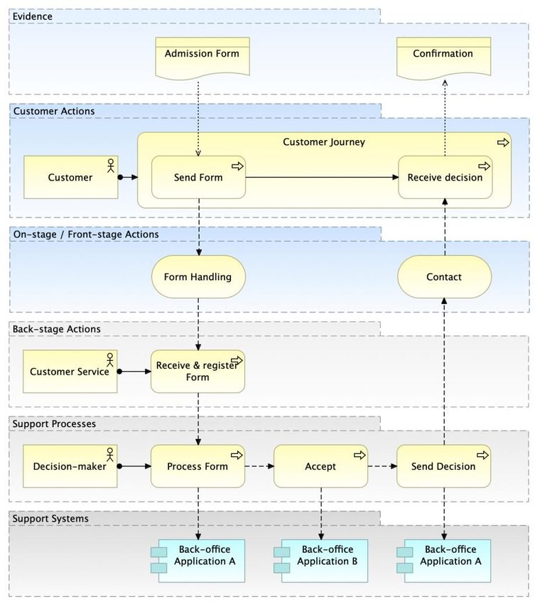
ArchiMate Cookbook
Patterns & Examples

2.2.3.1 Value Stream - Example

Figure 8: Value Stream - Example.
The Value Stream (figure above) represents the Business Model (added with value elements), whereas the
Business Process (figure below) represents the Operating Model (the implementation of the Value Stream). In that
case the value stream and process describe the same “thing”, but in different abstraction levels.

Figure 9: Relation of the Value Stream and the Business Process.
“A Business Model should also provide a very high-level view of the key parameters that together combine to
produce the value proposition. An Operating Model explains the configuration of the enterprise resources
considered optimal by the leadership team for the realization of the business model. In other words, how will the
business model be realized by some suitable combination of People, Process, and Technology (PPT)”. [Ed
Walters, Modeling the Business Model Canvas with the ArchiMate® Specification, Document No.: W195, Published
by The Open Group, May 2019.]
The topic of value stream analysis is covered in more detailed by Christine Dessus in “Value analysis with Value
Stream and Capability modeling” (see [8] ).

                                                 Eero Hosiaisluoma ©
                                                                                                                   10
ArchiMate Cookbook
Patterns & Examples
2.2.4 Strategy & Capability View
For the successful and efficient operational development of an
organization, it is crucial that the strategy and strategic goals can be
connected to the Business Model, to the Capability Model, to the
Operating Model, and preferably to all the development targets.
The strategy can be modelled with ArchiMate Strategy -elements: Course
of Action, Value Stream, Capability ja Resource. With these elements, the
organization can be analyzed and depicted according to Resource Based
View (RBV) -approach.
Figure 10: Strategy - Design
Pattern.
A Capability Map View, the Capability Model, is valuable to identify the following:
1) the strategic core capabilities, which constitute the fundaments of the existence of the organization (incl.
value creation, competitive advantage), and
2) the basic capabilities, which enables the daily operations of the organization.
For capability assessment and identification, the following can be considered:
• a capability defines WHAT the organization does (whereas a resource defines HOW),
• a capability is unambiguous (no overlaps), and relatively stable by its nature,
• a capability can be divided into more detailed, lower-level capabilities,
• a capability can be grouped into a capability group,
• a capability can be:
a. organizational (intangible, related to the existence, strategy or value creation of an organization)
or
b. operational (produced by tangible or intangible resources, related to the operating model).
2.2.4.1 Capability Map View
Figure 11: Capability Map View - Example.
A Capability Map View is modelled with ArchiMate Capability -elements. Capability Groups can be modelled with
either Capability- or Group-elements.
Eero Hosiaisluoma ©
11ArchiMate Cookbook
Patterns & Examples
2.2.4.2 Strategy & Capability Planning View
Figure 12: Strategy & Capability Planning View - Example (ref. “Strategy to Capability” Value Stream).
The Strategy View & Capability Planning View is modelled with ArchiMate Motivation- and Strategy-elements
(figure above). This view and these elements can be used for Capability-Based Planning (CBP) purposes.
Eero Hosiaisluoma ©
12ArchiMate Cookbook
Patterns & Examples
2.2.4.3 Strategy To Capability View
Figure 13: Strategy To Capability View - Example.
Another example of how Capability-Based Planning (CBP) can be supported by modelling. Capabilities can be
identified based on the strategic course of actions, which can be derived from strategic goals and -outcomes.
For the sake of enabling strategy execution in practice, the strategy statements should be expressed as
imperatives, actionable clearly stated clauses. These imperative actions can be modelled with ArchiMate Course of
Action -elements. A suggested form is use imperative as follows: “Focus on Customer Experience”, “Automatize
Biz Processes”, “Establish Demand Management virtual team” etc.
Eero Hosiaisluoma ©
13ArchiMate Cookbook
Patterns & Examples
2.2.4.4 Capability Planning View
Figure 14: Capability Planning View - Example.
This view can be used for designing the actual architectural building blocks to realize a capability. The Grouping -
element can be used for aggregating the elements into a logical entity.
2.2.5 Implementation Roadmap View
Figure 15: Implementation Roadmap View - Example.
This view can be used for modelling the implementation plan of a strategy or capability etc.
An implementation roadmap can be added with the core enterprise architecture elements (such as application
services) that are to be implemented in certain phases as illustrated in the figure below.
Eero Hosiaisluoma ©
14ArchiMate Cookbook
Patterns & Examples
Figure 16: Implementation Roadmap View - Example 2.
This version (figure above) can be used for grouping the changes into the implementation phases.
Eero Hosiaisluoma ©
15ArchiMate Cookbook
Patterns & Examples
2.3 Layered View
Figure 17: Layered View (Overview) - Basic Design Pattern.
The Layered View combines ArchiMate-elements from different ArchiMate-layers as follows: Business-,
Application- and Technology Layers.
The Layered View enables the development target to be analyzed and depicted as a layered “stack” as follows: first
the business aspects on the top, then application aspects in the next layer, and finally the technology aspects on
the bottom. This approach makes the overall big picture visible with all the necessary relationships between all the
behavioral and structural elements, which are meaningful in the context of the development target in hand.
The layers are connected with the services (of different kinds), so in that sense the Layered View is enabling the
Service-Driven Approach (SDA) to analyze and depict a development target. This diagram type is one of the most
useful and informative, because that makes it possible to visualize all the important relationships from bottom-up
and top-down between all the necessary elements on each layer (biz, app, tech).
This diagram type can be modelled with any elements of the ArchiMate layers.
Eero Hosiaisluoma ©
16ArchiMate Cookbook
Patterns & Examples
2.3.1 Layered View - Business- and Application Layers Example
Figure 18: Layered View Example - business and application layers.
This example diagram of the Layered View connects business and application layers via the application services.
2.3.2 Layered View - Business Layer
Figure 19: Layered View, Business Layer - Design Pattern. Note: business interfaces as “channels”.
Note! Business Interfaces 1-3 are nested into higher level business interface “Channels” with relation type
Composition. Accordingly, Business Services 1-3 are nested into higher level business service.
Eero Hosiaisluoma ©
17ArchiMate Cookbook
Patterns & Examples
The Layered View can be applied to what is appropriate for the purpose. For example, layers can be left out and
depict the development target from the certain viewpoint, e.g. from the business point of view like in the figure
above. However, the layered approach is always based on the top-down order of the elements: customers on the
top, then the business services and so on.
2.3.3 Layered View - Customer Service Journey
Figure 20: Customer Service Journey - Design Pattern.
The Layered View can also be taken from the customer viewpoint. Customer centric diagrams can be modelled as
Customer Service Journey or Service Blueprint diagrams. These diagram types combine the customer- and
organization viewpoints together. These are the “outside-in” and “inside-out” approaches.
2.3.3.1 Layered View - Customer Journey View - Example
Figure 21: Customer Service Journey - Example.
Eero Hosiaisluoma ©
18ArchiMate Cookbook
Patterns & Examples
The Customer Service Journey is a specialization of the Layered View, which combines business- and application
layer elements.
2.3.4 Layered View - Swimline Process View
Figure 22: Swimline Process View - Design Pattern.
This version of the Layered View combines business layer elements and application layer elements. This cross-
layer view can be used for modelling high-level process flow, in which application services and/or applications are
linked to. With this view, a business process can be illustrated at high-level with ArchiMate – without need for
BPMN modelling. In addition, this view enables connecting process steps to actual application services used.
In this example above Business process steps are performed by distinct business roles. Practically, business roles
A, B and C are assigned to business process elements with ArchiMate Assignment-relationship type. Business role
-elements are visualized as large objects that represent the “swimlanes”, and then the business process -elements
are “nested” into those business roles.
Eero Hosiaisluoma ©
19ArchiMate Cookbook
Patterns & Examples
2.3.5 Layered View - Service Design View
Figure 23: Service Design View - Design Pattern.
This version of the Layered View using “swimline style”, is focused on customer role. This view can be used for
service design purposes, for integrating “outside-in” and “inside-out” approaches into a one view. The customer
journey with phases (Pre-service period, Service period and Post-service period) is added into the customer role,
and channels added in between customer and personnel roles.
Business Process -elements are nested into Business Role -elements, which means that Business Roles are
assigned to Business Processes (in the model repository). In addition, Business Roles are nested into the Business
Actor, so the roles are assigned to the actor. Hence, there are relations between these elements, even though they
are not visible. This layout of the element saves space in the diagram. The value of this view is that we can use
ArchiMate and its relations when visualizing a “swimlines of roles with connected application services and
applications”.
The service layer is can be divided into distinct business services, if that is the case. Whether there is a certain
specific business service that is to be designed, or there are several business services with specific channels that
are serving the customer role. However, the focus is on the customer service path – on the customer journey, the
customer perspective. As such, this approach is focusing on the outside-in approach, by linking the inside-out
behavior and structure to customer facing process steps.
Eero Hosiaisluoma ©
20ArchiMate Cookbook
Patterns & Examples
2.3.6 Layered View - Service Blueprint
Figure 24: Service Blueprint - Example.
2.4 Interaction View (Co-operation View)
There are three variants of the Interaction View diagram type as follows:
1) Actor Interaction View,
2) Process Interaction View and
3) Application Interaction View.
The Interaction View (also known as Co-operation View or Integration View) can be used for modelling
relationships between the actors, processes or applications. The main advantage of this diagram type is to
visualize the direction of switching information, and to illustrate the amount of the interacting elements. This
diagram type has been found very informative and the easiest way to visualize the complexity of the development
target.
This diagram type is to be used for modelling WHAT information flows in WHICH direction, from WHERE to
WHERE. This diagram type is not applied for modelling the “dynamics” of the information switching: which element
starts the interaction or what interfaces are used.
The ArchiMate Flow-relationship type is used here to model the information flow between the elements. The
“information” can also be modelled as ArchiMate Business Objects or Data Objects.
Eero Hosiaisluoma ©
21ArchiMate Cookbook
Patterns & Examples
2.4.1 Actor Interaction (Co-operation) View
Figure 25: Actor Interaction (Co-operation) View - Design Pattern.
2.4.2 Process Interaction (Co-operation) View
Figure 26: Process Interaction (Co-operation) View - Design Pattern.
2.4.3 Application Interaction (Co-operation) View
Figure 27: Application Interaction (Co-operation) View - Design Pattern.
This version of this diagram type is used for modelling application integrations at high level: what data flows from
which application to which application, in which direction. For more detailed level integration modelling, these
diagrams can be added with e.g. application interfaces or -services, and Trigger-relationships (see chapter 2.9.7 ).
Eero Hosiaisluoma ©
22ArchiMate Cookbook
Patterns & Examples
2.5 Business Process View
Figure 28: Process View - Example.
Process View is modelled with ArchiMate Business Layer -elements as follows: Business Process), Business
Actor), Business Role, Business Object and Business Event. Relationship types are Trigger and Access.
2.5.1 Business Process Functional Decomposition View
Figure 29: Business Function View – A process may span multiple business functions.
“A business function represents a collection of business behavior based on a chosen set of criteria (typically
required business resources and/or competencies), closely aligned to an organization, but not necessarily explicitly
governed by the organization.” [1]
A business function view can be used when it is necessary to model high-level business behavior, which groups
more detailed behavior (such as processes). A business function is a behavioral element, which is performed by a
structural element, typically by an organizational unit (e.g. department or group). A business function is meaningful
behavior for the organization. Business functions can be used for dividing the business into parts, each of which
has certain logical cohesion based on the business services they provide.
Eero Hosiaisluoma ©
23ArchiMate Cookbook
Patterns & Examples
Figure 30: Business Process Map with Function-Based Decomposition.
A business process map can be defined based on functional decomposition (figure above). Note! Business units
shown here just to illustrate the typical mapping between business functions and business actors. Business actors
may not necessarily be shown in actual business process maps.
Examples of business functions are e.g. as follows: Finance and Accounting, Human Resources (HR),
Procurement (Buying/Purchasing), Legal, Customer Service, Property Management. A business function is close to
business capability, but they define business behavior in different abstraction levels: a business function represents
business behavior in the operating model level, whereas a business capability represents business behavior on the
business model level.
For more detailed discussion covering the relation of business processes and business functions, see the Gerben
Wierda’s book Mastering ArchiMate III [3].
2.6 Conceptual Data Model View
Figure 31: Conceptual Data Model View - Example.
The Conceptual Data Model View can be used for modelling the business concepts and their relations of the
development target.
This diagram type is modelled with ArchiMate Business Object -element, and Association, Composition,
Aggregation and Specialization relationship types. Some tools allow cardinality indicators (such as “one”, “many”,
“0..n”) to be modelled on both ends of the association relations between the elements.
Eero Hosiaisluoma ©
24ArchiMate Cookbook
Patterns & Examples
2.7 Data Model View
Figure 32: Data Model View - Example.
The Data Model View can be used for modelling the detailed, logical application level information and their relations
of the development target.
This diagram type is modelled with ArchiMate Data Object -element and Association, Composition, Aggregation
and Specialization relationship types. Some tools allow cardinality indicators (such as “one”, “many”, “0..n”) to be
modelled on both ends of the association relations between the elements.
2.8 Technology Platform View (Infrastructure View)
Figure 33: Technology Platform View - Design Pattern.
The Technology Platform View (Infrastructure View) can be used e.g. for modelling the underlying infrastructure
and deployment of an application (softwares, servers, clustering, communication networks, load balancing etc.).
This diagram type is modelled with ArchiMate Technology layer elements such as Node, Technology Service,
Artifact, Device, System Software, Technology Interface and Communication Network.
Eero Hosiaisluoma ©
25ArchiMate Cookbook
Patterns & Examples
Figure 34: Technology Platform - Example.
2.9 Application Structure View (Solution Architecture View)
The Solution Architecture defines the behavior and structure of a single solution, which is a part of the Enterprise
Architecture (EA). A solution is a logically and physically independent, autonomous building block of the
organization wide EA. In the EA, a solution is a “black box”: its interfaces and services are interesting, but its
internal structure is irrelevant. As such, a solution is the smallest meaningful unit of EA. EA is composed of
solutions. A solution can also be comprised as a “system”, whereas EA is a “system of systems”. Systemic thinking
takes the holistic view by identifying and considering all the aspects of business, application and technology.
Solution Architecture, instead, covers the application as a “white box”: its internal structure and interfaces with
adjacent applications are interesting. The solution architecture comprehends the internal structure of an
application: the modularization (sub-components and their services/interfaces and dependencies). In addition, the
solution architecture typically takes the technology aspect into account - in the form of “technology platform”.
2.9.1 Application Design Pattern (Basic Model)
Figure 35: Application View - Design Pattern (Basic Model).
Solution Architecture modelling can be done with the elements of ArchiMate Business, Application and Technology
layers. The logical view of the structure of a solution is modelled with ArchiMate Application layer elements such as
Application Component, Application Service, Application Interface, Application Process and Application Function.
The logical structure of a solution is modelled with ArchiMate Application Component -elements. The internal
behavior of an application is modelled with the Application Process and Application Function -elements. Provided
services and interfaces (to adjacent solutions) are modelled with Application Service and Application Interface -
elements. The Application Interface -element is used for modelling the user interfaces (GUIs) and app2app
interfaces (APIs).
Eero Hosiaisluoma ©
26ArchiMate Cookbook
Patterns & Examples
According to ArchiMate derivation rules (introduced in the ArchiMate specification), the basic application design
pattern can be depicted as shown below.
Figure 36: Application View - Design Pattern (Simplification of the Basic Model).
Note! Application services and application interfaces are the “different sides of the same coin”: a) behavioral
services and b) structural interfaces. Both can be used for modelling the behavior of an application that is exposed
for external use (interactions). Which one to use depends on the case. Application services can be used for
modelling functional dependencies and interactions. Application interfaces instead, can be used for modelling
concrete user interfaces (GUIs) or app2app interfaces (APIs) with operations. As such, application interfaces can
be used for modelling actual dynamics between applications, or between users and applications. Access -
relationship can be bi-directional (in case of read & write accessibility).
If an application interface is to be modelled instead of an application service, then the application interface is
connected with the application component with a Composition -relation type (figure below).
Figure 37: Application Component and (provided) Application Interface.
GUI = Graphical User Interface, API = Application Programming Interface, both interfaces of an
application. The former provides application services to the users, whereas the latter provides application
services to other applications. According to ArchiMate specification: “An application interface represents a
point of access where application services are made available to a user, another application component,
or a node” [1].
2.9.2 Application Logical Structure View (Application Structure / Internal Structure)
Figure 38: Application Logical Structure (functional decomposition into sub-components /modularization).
This view is useful in designing or understanding the main structure of an application and its sub-components and
the associated data. This diagram can be used e.g. to break down the structure of the application system under
construction, to illustrate modularization /decomposition: what are the sub-systems / sub-components what are the
application services (or application interfaces) they provide. The sub-components are nested into the main
component (Aggregation relationship).
Eero Hosiaisluoma ©
27ArchiMate Cookbook
Patterns & Examples
Figure 39: Application Logical Structure: sub-components and application services.
This view is useful in designing or understanding the main structure of an application, its sub-components and their
functions. This diagram can be used e.g. to break down the structure of the application system under construction,
to illustrate modularization (functional decomposition): what are the sub-systems / sub-components, what are the
functions and application services (or application interfaces) they provide.
Figure 40: Application Logical Structure: Application Functions assigned to modules of an application (A).
Note! The behavior (functions) of an application can be modelled with either ArchiMate Application Function or
Application Process -elements. The latter can also be used for modelling e.g. Robotic Process Automation (RPA)
or (scheduled) batch-processing behavior.
2.9.3 Component Model (CM)
Application Component Model 0-n (CM 0-n) is an application architecture modelling approach, which consists of
diagrams of different abstraction levels as follows:
• At Component Model 0 (CM-0) -level the diagram describes how the application interacts with its
environment, what are the boundaries and interactions with adjacent applications and users. The target
application is depicted as a black-box.
• At Component Model 1 (CM-1) -level the diagram describes how the target application is decomposed into
modules (main components), their responsibilities, and what application services (or application interfaces)
those modules provide and require. Logical decomposition of an application is based on the functional
aspects, which typically relates to physical decomposition too. The target application is depicted as a white-
box.
• At Component Model 2 (CM-2) -level, the diagrams describe how the main modules are decomposed into
sub-components, and what are their responsibilities, services or interfaces.
The Application Component Model (CM) diagrams below consist of application components and application
services. Alternatively, application interfaces can be used instead of application services depending on the case.
As always, it is important to utilize such a modelling style what is appropriate for the purpose, and model only those
elements that are relevant in the context, to fit for purpose. (Note! Application in this context is analogous to
solution or system.)
Eero Hosiaisluoma ©
28ArchiMate Cookbook
Patterns & Examples
2.9.3.1 Component Model - 0 (CM-0)
Figure 41: Component Model - 0 (CM-0).
The target application ”A” introduced in the middle of the diagram as a “black-box”, with all the application services
it provides, and with all the required services, realized by adjacent applications. This is the Enterprise Architecture
(EA) level view of the application: its internal structure is not relevant, but its services are.
2.9.3.2 Component Model - 1 (CM-1)
Figure 42: Component Model - 1 (CM-1).
The target application ”A” opened as a “white-box”, with all its internal sub-components (modules) shown with the
services they provide and require. This is the Solution Architecture (SA) level view of the application: its internal
behavior and structure is interesting (incl. e.g. internal application components, application processes, application
functions, and application services or application interfaces they provide and require).
Eero Hosiaisluoma ©
29ArchiMate Cookbook
Patterns & Examples
2.9.3.3 Component Model - 2 (CM-2)
Figure 43: Component Model - 2 (CM-2).
One of the main components (“A-2”) of the application “A” opened in a more detailed diagram.
2.9.4 Database
A database is a meaningful unit in the overall enterprise architecture of an organization. E.g. “Client database” or
“Customer database”, “Product database” etc. A logical database is a composition of all the tables of an application
(e.g. “Customer table”, “Orders table”, “Invoices table” etc.), which altogether build up a database.
A logical database can be modelled on the application layer with a) Data Object- or b) Application Component-
element. Which element to use, depends on what kind of database is in question: a) a passive structure or b) an
active structure. Data Object is suitable for modelling the passive data itself: what is the data, how it is structured or
composed (or aggregated) from other data objects, and what are the associations between these data objects.
Application Component is suitable for modelling an active data structure that is capable of data management
behavior such as data processing and/or data storing.
Figure 44: Modelling a logical database with ArchiMate.
A Data Object can be used for modelling for example a logical database, a database table, message structure
(switched between applications) etc.
A Data Model View consists of database tables as shown below. (See also chapter 2.7 ).
Eero Hosiaisluoma ©
30ArchiMate Cookbook
Patterns & Examples
Figure 45: Data Model View.
A logical database can be modelled also with the Application Component, given that the database is capable of
performing data processing or data storing. In such a case, a database is part of an application: a logical
component of an application. (Other modular parts/components of an application can be for example “the front-end
application” and “the business logic application”).
Figure 46: Database as a component of an application system.
In addition, a database can be modelled with technology layer elements such as Node, Artifact or System
Software. All in all, there are several ways to model a database, depending on the abstraction level, as shown in
the figure below. It depends on the case, from which viewpoint a database is to be modelled, e.g. from the
application viewpoint as a logical entity, from technology viewpoint as a physical construct etc.
Figure 47: Database modelling in different abstraction levels.
Eero Hosiaisluoma ©
31ArchiMate Cookbook
Patterns & Examples
2.9.5 Application Integrations
2.9.5.1 Application Interface and Synchronic Request-Reply Design Pattern
Figure 48: Application Interface and Synchronic Request-Reply Design Pattern.
This pattern illustrates the following system case:
The application “A” provides the application interface “A-1”, which is used by application “B”. The
application “B” calls the interface “A-1” and transfers parameters within the request message, and
gets the response back within the message structure “Data Object A-1”. The application “B” is the
active party that initiates the interaction (information switching).
This view is modelled with dynamic relations of ArchiMate: Trigger and Flow.
For more detailed Application Integration Patterns, see Appendix 2 (2.9.7 ).
2.9.5.2 ETL-Process
Figure 49: ETL-process - Design Pattern.
This ETL-process (Extract, Transform, Load) pattern view is modelled with Application Process and Data Object -
elements. An ETL-process reads from the source table(s), performs some processing, and then writes to the target
table(s) (figure above). The ETL-process can be assigned to the Application Component with Assignment-
relationship (figure below). Note! Behavior (such as process or function) is always performed by an active structure
element (e.g. an application component)!
Figure 50: ETL-process, tables and assigned application.
2.9.6 Sequence Diagrams
2.9.6.1 Application Component Sequence Diagram View
Sequence diagrams are not exactly in scope of the ArchiMate (or EA), but instead, those are in scope of the UML
(and SA). However, we can use ArchiMate for modelling sequences of actions taken by e.g. Application
Components as shown below.
Eero Hosiaisluoma ©
32ArchiMate Cookbook
Patterns & Examples
Figure 51: Application Sequence View.
Dynamic relations “Trigger” and “Flow” can be used for modelling dynamics between application components. The
layout of this view can be positioned analogously to the UML sequence diagram.
2.9.6.2 Application Component Sequence Diagram View 2
This version (diagram below) illustrates how ArchiMate can be used for modelling sequences of actions taken by
internal parts of Application Components. The internal parts are such as a) behavioral processes or functions and
b) structural sub-components. These are modelled with Application Process-, Application Function- and Application
Component -elements. Those are shown here just as alternatives.
Figure 52: Application Sequence View (2).
The flow of actions in this sequence diagram (above):
1. The Application Component A’s sub-process X sends a request message with parameter A to the
Application B.
2. The Application Component B’s sub-process B-1 receives the incoming request, and then calls
(synchronously) Application Component C, in which Application Function Y receives the request, performs
some actions and responds back.
3. The Application Component B’s other sub-process B-2 sends a message with parameters to the
Application Component D, and then receives an acknowledgment. The Application Component D contains
a sub-component that executes the processing.
4. The Application Component A receives the response message from the Application Component B.
As shown here, we can model quite complex integration mechanisms with a combination of these elements
(Application Component, Application Process and Application Function and relations (Trigger, Flow). UML
sequence diagram has its own specialized purpose in software design, but ArchiMate can be utilized in quite a
many modelling purposes - also in application design.
Application integration is one of the most important parts of the enterprise architecture. That is why it is
advantageous if we can model more detailed how applications switch data, and what are the interaction
mechanisms used. A good source to dive into integration patterns, see “Enterprise Integration Patterns” -book,
here is the link: https://www.enterpriseintegrationpatterns.com/ .
Eero Hosiaisluoma ©
33ArchiMate Cookbook
Patterns & Examples
2.9.7 Application Integration Patterns
Figure 53: Application Integration Patterns.
Eero Hosiaisluoma ©
34ArchiMate Cookbook
Patterns & Examples
2.9.8 Use Case View
Figure 54: Use Case View - Design Pattern.
ArchiMate can be used for modelling the use case diagrams. A business actor can be associated with the
application services, which represent the use cases of the target application. These application services are the
functionalities of the target application, and they can be used in other diagrams (such as Layered View).
The intrinsic value of this approach: we can use ArchiMate throughout the design cycle. From the business
requirements gathering phase to the further detailed design phase. The same language, the same tool. No need for
switching between UML and ArchiMate, or from one tool to another 1. Application services can be used when we
initially define what the application should do, and how the user roles use the application, and then finally, these
already identified application services can be used in later design phases within diverse diagram types.
Figure 55: Use Case Analysis Views.
Use Case analysis can be performed by the following steps:
1. Use Cases are identified by using application services (analogous to UML Use Case Diagram)
2. Relation types are changed from Association to Serving (optional step)
3. Application is added to realize the application services (optional step)
4. Elements are positioned on the Layered View layout.
1
Some tools support many notations such as ArchiMate, BPMN and UML, like Sparx EA for example.
Eero Hosiaisluoma ©
35ArchiMate Cookbook
Patterns & Examples
The diagrams 1-4 above are just mentioned here for information. Diagrams 1 and 4 can be kept as part of the
documentation of the target application (here: Application Component X).
2.9.8.1 Use Case View - Example
Figure 56: Use Case View - Example.
A use case can be depicted with a layered view (figure above). The main use case can be modelled as a Business
Service, the flow of actions can be modelled with Business Process -elements, and the related system-level use
cases (a.k.a. System Cases) can be modelled with Application Service -elements.
The diagram below just illustrates how we can use add-on visual elements to point which elements are identified as
new or modified parts of the development target area (the problem domain).
Figure 57: Use Case View - Example 2.
Eero Hosiaisluoma ©
36ArchiMate Cookbook
Patterns & Examples
Once again we can see how the layered view can be applied to diverse modelling needs (=“use cases”).
3. ArchiMate-Elements (subset)
Figure 58: Subset of ArchiMate-elements.
These ArchiMate-elements covers the most cases (80% of diagrams can be modelled with these elements).
The subset of ArchiMate -elements are introduced in the following tables (based on ArchiMate specification [1]).
ArchiMate-elements are grouped into following categories: active structure, behavior and passive structure. In
addition, there are certain composite elements as follows: Grouping, Location and Product.
Active structure element can be regarded as a “subject”, behavior element as a “predicate” (verb”), and passive
structure element as an “object”.
Eero Hosiaisluoma ©
37ArchiMate Cookbook
Patterns & Examples
3.1 ArchiMate Motivation -Elements
ArchiMate Motivation- Elements (Motivation View) - Motivation Aspect
Name Description Symbol
Stakeholder The role of an individual, team, or organization that represents
their interests in the outcome of the architecture (development
target).
Driver An external or internal condition that motivates an organization
to define its goals and implement the changes necessary to
achieve them. Defines the WHY a change is important.
Assesment The result of an analysis of the state of affairs of the enterprise
with respect to some driver. Can be used e.g. in SWOT-
analysis.
Goal A high-level statement of intent, direction, or desired end state
for an organization and its stakeholders.
Outcome An end-result that has been achieved. High-level, business-
oriented results produced by capabilities, tangible, possibly
quantitative.
Principle A qualitative statement of intent that should be met by the
architecture.
Requirement A statement of need that must be met by the architecture.
Constraint A factor that prevents or obstructs the realization of goals.
Value The relative worth, utility, or importance of a core element or
an outcome.
Eero Hosiaisluoma ©
38You can also read