Using MCUboot with RA Family MCUs - Renesas
←
→
Page content transcription
If your browser does not render page correctly, please read the page content below
Application Note

Renesas RA Family
Using MCUboot with RA Family MCUs
Introduction
MCUboot is a secure bootloader for 32-bit MCUs. It defines a common infrastructure for the bootloader,
defines system flash layout on microcontroller systems, and provides a secure bootloader that enables easy
software update. MCUboot is operating system and hardware independent and relies on hardware porting
layers from the operating system it works with. The Renesas Flexible Software Package (FSP) integrates an
MCUboot port starting from FSP v3.0.0. Users can benefit from using the FSP MCUboot Module to create a
Root of Trust (RoT) for the system and perform secure booting and fail-safe application updates.
The MCUboot is maintained by Linaro in the GitHub mcu-tools page https://github.com/mcu-tools/mcuboot.
There is a \docs folder that holds the documentation for MCUboot in .md file format. This application note
will refer to the above-mentioned documents wherever possible and is intended to provide additional
information that is related to using the MCUboot Module with Renesas RA FSP v3.0.0 or later.
This application note walks the user through application project creation using the MCUboot Module on
Renesas EK-RA6M4 and EK-RA6M3 kits. Example projects for the use case of designing with TrustZone for
multi-image support is provided for EK-RA6M4. Example projects for the use case of designing with single
image support is provided for EK-RA6M3. The MCUboot Module is supported across the entire RA MCU
Family. Guidelines of how to adapt the example project configurations for other RA Family MCUs are
provided.
Required Resources
Development tools and software
•   The e2 studio ISDE v2021-04 or greater
•   Renesas Flexible Software Package (FSP) v3.0 or later
•   SEGGER J-link® USB driver

The above three software components: the FSP, J-Link USB drivers and e2 studio are bundled in a
downloadable platform installer available on the FSP webpage at renesas.com/ra/fsp.
•   Python v3.8 or later- https://www.python.org/downloads/

Hardware
•   EK-RA6M4 Evaluation Kit for RA6M4 MCU Group (http://www.renesas.com/ra/ek-ra6m4)
•   EK-RA6M3 Evaluation Kit for RA6M3 MCU Group (http://www.renesas.com/ra/ek-ra6m3)
•   Workstation running Windows® 10 and Tera Term console, or similar application
•   Two USB device cables (type-A male to micro-B male)

Prerequisites and Intended Audience
This application note assumes you have some experience with the Renesas e2 studio IDE and Arm®
TrustZone® based development models with e2 studio. Users are required to read the entire FSP User’s
Manual on the MCUboot Port section prior to moving forward with this application project. In addition, the
application note assumes that you have some knowledge of cryptography. Prior knowledge of Python usage
is also helpful.
The intended audience are product developers, product manufacturers, product support, or end users who
are involved with designing application systems involving usage of a secure bootloader.

R11AN0497EU0100 Rev.1.00                                                                       Page 1 of 51
May.12.2021
Renesas RA Family                                                                           Using MCUboot with RA Family MCUs
Contents

1.      Overview of MCUboot ..............................................................................................................4
1.1      History of MCUboot ................................................................................................................................. 4
1.2      MCUboot Functionalities Overview ......................................................................................................... 4
1.2.1      Validate Application before Booting and Updating ................................................................................ 4
1.2.2      Applications Update Strategies ............................................................................................................ 4

2.      Architecting an Application with MCUboot Module using FSP .................................................. 6
2.1      MCU Memory Configuration using MCUboot Module with FSP ............................................................. 6
2.2      Overview of FSP MCUboot Module ........................................................................................................ 6
2.2.1      General Configurations ......................................................................................................................... 7
2.2.2      Application Image Signature Type Options ........................................................................................... 8
2.2.3      Signing Options ..................................................................................................................................... 9
2.2.4      MCU Memory Configuration ................................................................................................................ 10
2.3      Designing Bootloader and the Initial Primary Application Overview ..................................................... 11
2.4      General Guidelines using the MCUboot Module Across RA Family MCUs .......................................... 11
2.5      Customize the Bootloader ..................................................................................................................... 11
2.6      Production Support ................................................................................................................................ 11
2.6.1      Key Provisioning .................................................................................................................................. 11
2.6.2      Make the bootloader immutable for enhanced security ...................................................................... 12
2.6.3      Advance the device lifecycle states prior to the deploy the product to the field. ................................. 12
2.7      MCUboot Module Usage Notes When Using with FSP ........................................................................ 12

3.      Running the Example Projects ............................................................................................... 12
3.1      Set Up the Python Image Signing Environment .................................................................................... 13
3.2      Running the EK-RA6M4 Example Projects with Overwrite Update Modes .......................................... 13
3.2.1      Set Up the Hardware ........................................................................................................................... 14
3.2.2      Import the projects under \ra6m4_overwrite_with_bootloader to a workspace .................... 15
3.2.3      Configure the Python Signing Environment ........................................................................................ 15
3.2.4      Compile all the projects ....................................................................................................................... 16
3.2.5      Debug the Applications ....................................................................................................................... 17
3.2.6      Download the Secure Image ............................................................................................................... 17
3.2.7      Download the Non-Secure Image ....................................................................................................... 17
3.2.8      Open the J-Link RTT Viewer and Set Up Configurations ................................................................... 18
3.2.9      Downloading and Running the Secondary Applications ..................................................................... 19
3.2.10 Non-Secure Secondary image can be updated independent of the secure secondary image ........... 20
3.3      Running the EK-RA6M4 Example Project with Swap Update Modes ................................................... 20
3.4      Running the EK-RA6M3 Example Projects with Overwrite Update Modes .......................................... 24
3.4.1      Import the projects under folder \ra6m3_overwrite_with_bootloader to a workspace .......... 24
3.4.2      Configure the Python Signing Environment ........................................................................................ 24
3.4.3      Compile the projects ............................................................................................................................ 25

R11AN0497EU0100 Rev.1.00                                                                                                                      Page 2 of 51
May.12.2021
Renesas RA Family                                                                           Using MCUboot with RA Family MCUs
3.4.4      Initialize the MCU ................................................................................................................................ 25
3.4.5      Start the debug session from the Primary application......................................................................... 25
3.4.6      Download the Primary image .............................................................................................................. 25
3.4.7      Downloading and Running the Secondary Applications ..................................................................... 27
3.5      Updating the EK-RA6M3 Example Projects from Overwrite to Swap Update Mode ............................ 28

4.      Creating and Using the Bootloader with Existing Application with Cortex-M33....................... 29
4.1      Creating a Bootloader Project for RA Family Cortex-M33 MCU ........................................................... 29
4.1.1      Start Bootloader Project Creation with e2 studio ................................................................................. 29
4.1.2      Resolve the Configurator Dependencies ............................................................................................ 31
4.1.3      Setting up the Booting Authentication Support ................................................................................... 33
4.1.4      Setting up the Application Authentication Signature Type .................................................................. 34
4.2      Configure Existing Application Projects to Use the Bootloader ............................................................ 35
4.2.1      Import the Standalone Application Projects ........................................................................................ 35
4.2.2      Configure the Application Projects to Use the Bootloader .................................................................. 35
4.3      Signing the Existing Application Projects to Use the Bootloader .......................................................... 36
4.3.1      Create the Post Build Signing Command ............................................................................................ 36
4.3.2      Configure the post build command in e2 studio ................................................................................... 39
4.3.3      Click Generate Project Content and compile all four application projects. ......................................... 40
4.3.4      Configure the debug configuration ...................................................................................................... 41

5.      Creating and Using the Bootloader with Existing Cortex-M4 Applications .............................. 43
5.1      Creating a Bootloader Project for RA Family Cortex-M4 MCUs ........................................................... 43
5.1.1      Start the Bootloader Project Creation with e2 studio ........................................................................... 43
5.1.2      Resolve the Configurator Dependencies ............................................................................................ 44
5.2      Configure the Existing Application Projects to Use the Bootloader ...................................................... 45
5.3      Signing the Existing Application to Use the Bootloader ........................................................................ 46

6.      Mastering and Delivering a New Application .......................................................................... 48

7.      Appendix ............................................................................................................................... 49
7.1      Making the Bootloader for Cortex-M33 Immutable ............................................................................... 49
7.2      Making the Bootloader for Cortex-M4 Immutable ................................................................................. 49
7.3      Device Lifecycle Management for Renesas RA Cortex-M33 MCUs ..................................................... 49
7.4      Device Lifecycle Management for Renesas RA Cortex-M4 MCUs ....................................................... 50

8.      References ............................................................................................................................ 50

9.      Website and Support ............................................................................................................. 50

Revision History ............................................................................................................................ 51

R11AN0497EU0100 Rev.1.00                                                                                                                      Page 3 of 51
May.12.2021
Renesas RA Family                                               Using MCUboot with RA Family MCUs
1. Overview of MCUboot
1.1     History of MCUboot
MCUboot has evolved out of the Apache Mynewt bootloader, which was created by runtime.io. MCUboot
was then acquired by JuulLabs in November 2018. The MCUboot github repo was later migrated from
JuulLabs to the mcu-tools github project. In year 2020, the MCUboot was moved under the Linaro
Community Project umbrella as an open source project.
1.2     MCUboot Functionalities Overview
MCUBoot handles the firmware authenticity check after start-up and the firmware switch part of the firmware
update process. Downloading the new version of the firmware is out-of-scope for MCUBoot. Typically,
downloading the new version of the firmware is functionality that is provided by the application project itself.
1.2.1    Validate Application before Booting and Updating
For applications using MCUboot, the MCU memory is separated into MCUboot, Primary App, Secondary App
and the Scratch Area. Below is an example of the single image MCUboot memory map. For more
information on the MCUboot memory layout, refer to the Flash Map section of the reference MCUboot
website.

                             Figure 1. Single Image MCUboot Memory Flash Map
The functionality of the MCUboot during booting and updating follows the process below:
The bootloader is started when CPU is released from reset. For TrustZone-based MCUs, MCUboot is
designed to run in secure mode with all access privileges available to it. If there are images in the Secondary
App memory marked as to be updated, the bootloader performs the following actions:
1. The bootloader will authenticate the Secondary image
2. Upon successful authentication, the bootloader will switch to the new image based on the update
   method selected. Available update methods are introduced in section 1.2.2.
3. The bootloader will boot the new image
If there is no new image in the Secondary App memory region, the bootloader will authenticate the Primary
applications and boot the Primary image.
The authentication of the application is configurable in terms of the authentication methods and whether the
authentication is to be performed with MCUboot. If authentication is to be performed, the available methods
are RSA or ECDSA. The firmware image is authenticated by hash (SHA-256) and digital signature validation.
The public key used for digital signature validation can be built into the bootloader image or provisioned into
the MCU during manufacturing. In the examples included in this application project, the public key is built into
the bootloader images.
There is a signing tool included with the MCUboot: imgtool.py. This tool provides services for creating Root
keys, key management, and signing and packaging an image with version controls. User needs to read the
MCUboot documentation to use and understand these operations.
1.2.2    Applications Update Strategies
The following are the update strategies supported by MCUboot. The Renesas FSP MCUboot Module in FSP
v3.0.0 does not yet support all of the MCUboot update strategies. The analysis of pros and cons is based on
the MCUboot functionality, but not the FSP v3.0.0 MCUboot Module functionality. In addition, this application
note is not intended to provide all details on the MCUboot application update strategies. We recommed
acquiring more details on these update strategies by referring to the MCUboot design page:

R11AN0497EU0100 Rev.1.00                                                                           Page 4 of 51
May.12.2021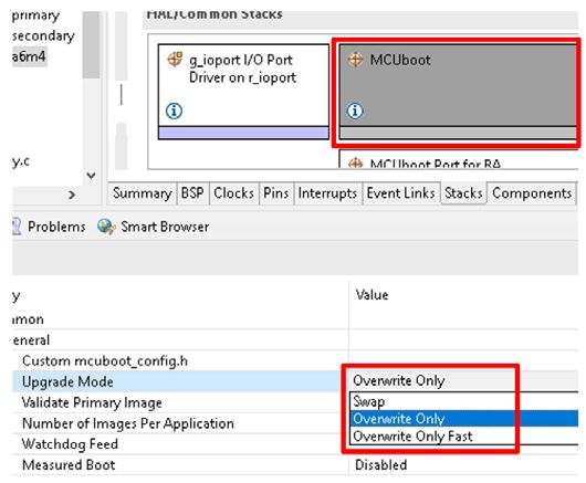
Renesas RA Family                                             Using MCUboot with RA Family MCUs
https://github.com/mcu-tools/mcuboot/blob/master/docs/design.md.
•   Overwrite
    In the Overwrite update mode, the active firmware image is always executed from the Primary slot, and
    the Secondary slot is a staging area for new images. Before the new firmware image is executed, the
    entire contents of the primary slot is overwritten with the contents of the secondary slot (the new
    firmware image).
    • Pros
         • Fail-safe and resistant to power-cut failures.
         • Less memory overhead, with a smaller MCUboot trailer and no scratch area.
         • Encrypted image support available when using external flash.
    • Cons
         • Does not support pre-testing of the new image prior to overwrite.
         • Does not support automatic application fall-back mechanism.
    Overwrite upgrade mode is supported by Renesas RA FSP v3.0.0 or later. FSP v3.0.0 does not support
    image storage in external flash memory and image encryption.
•   Swap
    In the Swap image upgrade mode, the active image is also stored in the Primary slot and it will always
    be started by the bootloader. If the bootloader finds a valid image in the Secondary slot that is marked
    for upgrade, then contents of the primary slot and the secondary slot will be swapped. The new image
    will then start from the primary slot.
    • Pros
         • The bootloader can revert the swapping as a fallback mechanism to recover the previous
             working firmware version after a faulty update.
         • The application can perform a self-test to mark itself permanent.
         • Fail-safe and resistant to power-cut failures.
         • Encrypted image support available when using external flash.
    • Cons
         • Need to allocate a scratch area
         • Larger memory overhead, due to a larger image trailer and additional scratch area.
         • Larger number of write cycles in the scratch area, faster wearing out of scratch sectors.
    Swap upgrade mode is supported by Renesas RA FSP v3.0.0 or later. Runtime image testing is not
    supported in FSP v3.0.0. In addition, FSP v3.0.0 does not support image storage in external flash
    memory and image encryption.
•   Direct execute-in-place (XIP)
    In the direct execute-in-place mode, the active image slot alternates with each firmware update. If this
    update method is used, then two firmware update images must be generated: one of them is linked to be
    executed from the primary slot memory region, and the other is linked to be executed from the
    secondary slot.
    • Pros
         • Faster boot time, as there is no overwrite or swap of application images needed.
         • Fail-safe and resistant to power-cut failures.
    • Cons
         • Added application-level complexity to determine which firmware image needs to be downloaded.
         • Encrypted image support is not available.
    Direct execute-in-place is not currently supported by the Renesas RA FSP, but it is planned for a future
    release.

R11AN0497EU0100 Rev.1.00                                                                       Page 5 of 51
May.12.2021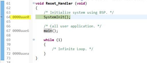
Renesas RA Family                                              Using MCUboot with RA Family MCUs
•     RAM loading firmware update
      Like the direct-xip mode, RAM loading firmware update mode selects the newest image by reading the
      image version numbers in the image headers. However, instead of executing it in place, the newest
      image is copied to RAM for execution. The load address (the location in RAM where the image is copied
      to) is stored in the image header. This upgrade method is not typically used in MCU environment. Please
      refer to the RAM Loading section in the MCUboot page for more information on this update strategy.
      This image update mode does not support encrypted images (see MCUboot documentation on
      encrypted image operation).
      RAM loading update mode is not supported by the Renesas RA FSP.

2. Architecting an Application with MCUboot Module using FSP
This section provides an overview of the FSP MCUboot Module, which integrates MCUboot as a module into
the FSP. The available upgrade modes and memory architecture design are discussed. In addition, signing
and mastering new images are discussed.
2.1     MCU Memory Configuration using MCUboot Module with FSP
For single image projects, the default memory map looks likes exactly like Figure 1 as shown previously. For
applications with two separately updateable images, such as TrustZone applications where the Secure and
Non-Secure images can be updated separately, the default memory map looks like Figure 2 as shown
below.

                       Figure 2. Two Image MCUboot Module Memory Map (TrustZone)
2.2     Overview of FSP MCUboot Module
This section provides a high-level overview of the MCUboot Module in the FSP. Currently, the FSP supports
three firmware update methods:
•     Overwrite Only: The entire primary slot is overwritten with the secondary slot.
•     Overwrite Only Fast: Only sizeof(secondary_image) is copied into primary slot. Unused sectors are not
      copied.
•     Swap: The entire primary and secondary slots are swapped. A scratch region is required.

This application project provides the following example projects for the Overwrite Only and Overwrite Only
Fast update modes:

R11AN0497EU0100 Rev.1.00                                                                        Page 6 of 51
May.12.2021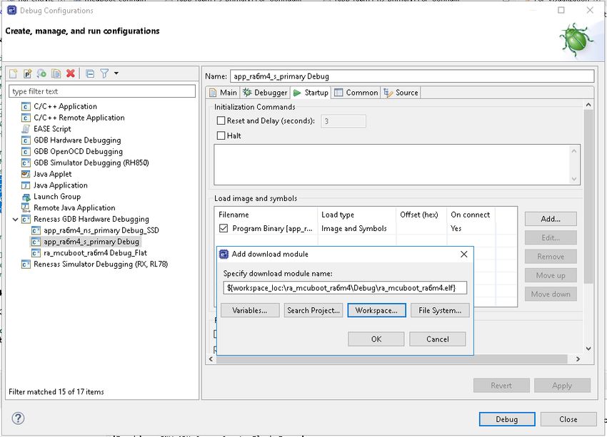
Renesas RA Family                                              Using MCUboot with RA Family MCUs
•   A set of example projects using Overwrite Only update mode are provided for EK-RA6M4 with Cortex-
    M33 TrustZone support
•   A set of example projects using Swap mode are provided for EK-RA6M4 with Cortex-M33 TrustZone
    support
•   A set of example projects using Overwrite Only update mode are provided for EK-RA6M3 with Cortex-
    M4 support.
•   Refer to section 3.5 for instructions on how to reconfigure the Overwrite Update Mode based EK-RA6M3
    projects to Swap Update Mode.

We recommended reviewing the FSP User’s Manual for the MCUboot Port section to understand the Build
Time Configurations for MCUboot. This section is not meant to cover all the configurable properties; only
some of the most frequently used configuration options are introduced.
2.2.1   General Configurations

                     Figure 3. FSP MCUboot Module General Configuration Properties
The following explains the various properties:
•   Custom mcuboot_config.h: The default mcuboot_config.h file contains the MCUboot Module
    configuration that the user selected from the RA configurator. The user can create a custom version of
    this file to achieve additional bootloader functionalities available in MCUboot. For example, the user can
    enable application image rollback prevention for image update when using the Overwrite update mode
    by enabling the macro definition MCUBOOT_DOWNGRADE_PREVENTION.
•   Upgrade Mode: This property configures the application image update method selection explained at
    the beginning of section 2.2. The options are Overwrite Only, Overwrite Only Fast and Swap. Overwrite
    Only is the default setting.

R11AN0497EU0100 Rev.1.00                                                                         Page 7 of 51
May.12.2021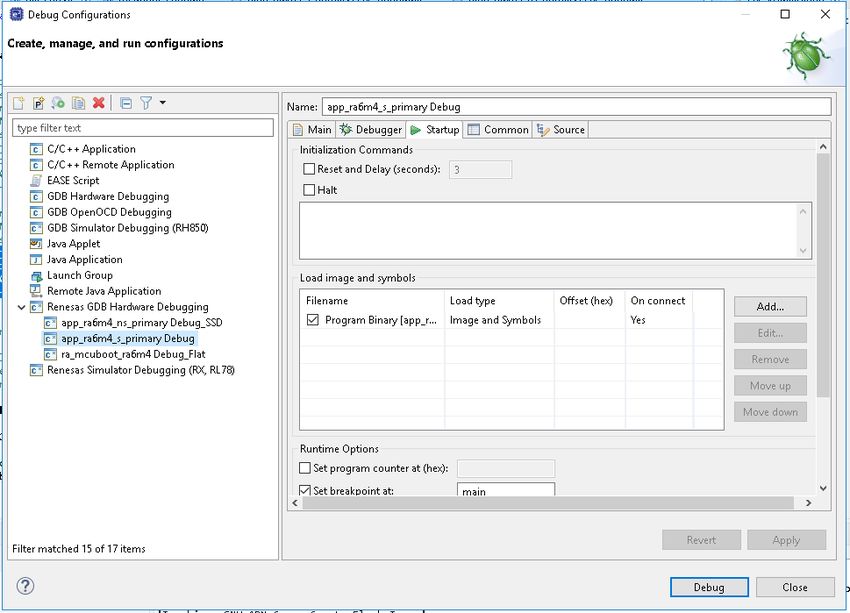
Renesas RA Family Using MCUboot with RA Family MCUs
Figure 4. Application Image Update Mode
• Validate Primary Image: This property allows the user to choose whether to validate the Primary Image
prior to boot. By default, the Primary Image Validation is enabled.
• Number of Images Per Application: This property allows user to choose one image for Non-
TrustZone-based applications and two images for TrustZone-based applications.
2.2.2 Application Image Signature Type Options
Application images using MCUboot must also be signed to work with MCUboot. At a minimum, this involves
adding a hash and an MCUboot-specific constant value in the image trailer.
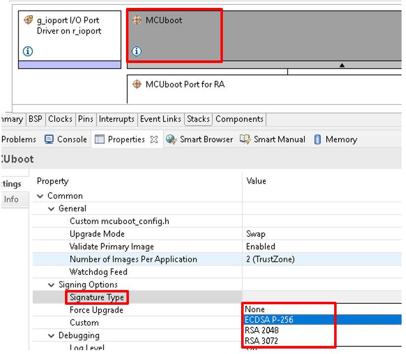
Figure 5 shows the signature types available for the application image signing methods supported by the
MCUboot Module. For memory restricted devices, users can choose None for Signature Type, which will
reduce the bootloader size. For example, the example bootloader for the Overwrite update mode uses a
flash area of 64 KB when using ECDSA P-256 signature type, but when signature support is not used, the
bootloader reduces to about 19 KB.
R11AN0497EU0100 Rev.1.00 Page 8 of 51
May.12.2021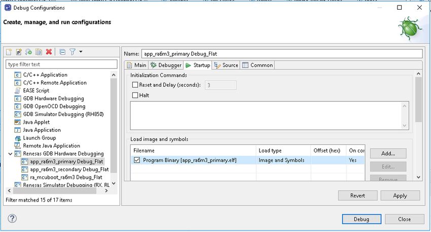
Renesas RA Family                                             Using MCUboot with RA Family MCUs

                  Figure 5. Application Image Signature Type for FSP MCUboot Module
2.2.3   Signing Options
Figure 6 shows the default Custom signing option configuration provided by FSP.

                                    Figure 6. FSP Default Signing Option
By default, FSP sets --confirm for the Custom property for both Image 1 and Image 2 when TrustZone is
used. For TrustZone-based applications, the Secure Image (Image 1) and Non-Secure Image (Image 2) can
have different configuration such that there is different update policy for the Secure and Non-Secure Images.
Below is the explanation of some commonly used signing options.

R11AN0497EU0100 Rev.1.00                                                                        Page 9 of 51
May.12.2021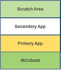
Renesas RA Family Using MCUboot with RA Family MCUs
• Option --pad:
This option places a trailer on the image that indicates that the image should be considered an upgrade.
Writing this image in the secondary slot will then cause the bootloader to upgrade to it. When Swap
mode is selected, this option generates a signing command such that the Secondary image will first be
swapped with the Primary application image. On the next reset, the Primary application previously used
will be swapped back and rebooted.
• Option --confirm:
When Swap mode is selected, this option generates a signing command such that the Secondary image
will first be swapped with the Primary application. At the next reset, there will be no swap between the
Primary and Secondary application and the Secondary application will be booted. Confirm is the default
Force Upgrade configuration.
• No input:
If no option is put in this property, application images signed with the signing command generated from
this setting will not be updated.
When Overwrite mode is selected, the --pad or --confirm options both generate signing commands such
that the overwrite will happen and the Secondary application will overwrite the Primary application.
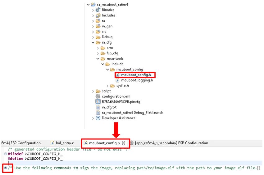
A template for signing the new firmware image based on the properties specified in the MCUboot Module is
output in a comment at the top of ra_cfg/mcu-
tools/include/mcuboot_config/mcuboot_config.h. Signing can be done as a post-build step in
e2 studio.
The image signing tool Imgtool.py is included with MCUboot. It is integrated as a post-build tool in e2 studio
to sign the application image. For detailed information about using this tool with e2 studio, please refer to the
application image signing information in sections 4.3 and 5.3. For more information on the possible options
available for this property setting, refer to the description in the imagetool.py md file and visit the MCUboot
documentation page https://mcuboot.com/mcuboot/imgtool.html.
2.2.4 MCU Memory Configuration
Figure 7 shows the default memory configuration options provided by the FSP configurator.
Figure 7. MCU Memory Configuration Default Settings
For both single-image and two-image configurations, the following four properties need to be defined:
• Bootloader Flash Area: Size of the flash area allocated for the bootloader.
• Image 1 Header Size: Size of the flash area allocated for the application header for single image
configuration or the secure application image header size in the case of a TrustZone-based application.
The recommended size from FSP requirement is 0x80.
• Image 1 Flash Area Size: Size of the flash area allocated for the application image for single image
configuration or the secure application image in the case of a TrustZone-based application.
• Scratch Flash Area Size: This property is only needed for Swap mode. The scratch area must be large
enough to store the largest sector that is going to be swapped. For both RA6M4 and RA6M3, the scratch
area is set up to be 32k (0x8000).
The properties under TrustZone are for TrustZone-based applications.
• Non-Secure Callback Region Size (Bytes): This area is used for the TrustZone Non-Secure Callable
area plus the MCUboot trailer. This property needs to be set to a multiple of 1024 bytes. Each Non-
Secure Callable function takes 8 bytes of flash area. The non-secure callback function usage can be
R11AN0497EU0100 Rev.1.00 Page 10 of 51
May.12.2021Renesas RA Family Using MCUboot with RA Family MCUs
identified by referring to the section .sgstub in the secure application map file. For Swap mode, the
MCUboot trailer size is calculated as 128*(5+(3*BOOT_MAX_IMG_SECTORS).
BOOT_MAX_IMG_SECTORS is the number of flash sectors in either the secure or the non-secure
image, whichever is larger. For Overwrite mode, the image trailer is less than 256 bytes, for a typical
application with limited number of Non-Secure Callable APIs, it is recommended to set the Non-Secure
Callable Region Size to 0x400.
• Non-Secure Flash Area Size: Size of the Non-Secure flash region. The user can compile the non-
secure application to get the size of the image and set this value accordingly. This value must be a
multiple of the flash block size.
• Non-Secure RAM Region Size: Size of the Non-Secure RAM region. This must be non-zero.
• Image 2 Header Size: The non-secure application header size. The recommended size from FSP
requirement is 0x80.
2.3 Designing Bootloader and the Initial Primary Application Overview
A bootloader is typically designed with the initial primary application. The following are the general guidelines
for designing the bootloader and the initial primary application.
• Develop the bootloader and analyze the MCU memory resource allocation needed for the bootloader
and the application. The bootloader memory usage is influenced by the application image update mode,
signature type and whether to validate the Primary Image. The bootloader maintains a memory map of
all the different images shown in Figure 1 and Figure 2.
• Develop the initial primary application, perform the memory usage analysis, and compare with the
bootloader memory allocation for consistency and adjust as needed.
• Determine the bootloader configurations in terms of image authentication and new image update mode.
This may result in adjustment of the memory allocated definition in the bootloader project.
• Test the bootloader and the initial primary application.
Most of these design aspects are addressed in the walk-through in section 4 and section 5. User can refer to
those sections in their specific application design.
2.4 General Guidelines using the MCUboot Module Across RA Family MCUs
The MCUboot Module is supported on all RA Family MCUs.
For the Renesas RA Cortex-M33 MCU series, refer to the RA6M4 example projects demonstrated in this
application project.
For the Renesas RA Cortex-M4 MCUs RA6 MCU series, refer to the RA6M3 example projects demonstrated
in this application project.
For the Renesas RA Cortex-M23 MCU series, the user needs to disable the following options to reduce the
bootloader flash usage size to under 20kB:
• Signing option: set Signature Type to None (refer to Figure 5)
• Follow the MbedTLS (Crypto only) stack RA configurator prompt to remove RSA and ECC.
In addition, for the RA Cortex-M23 MCU series, the user needs to enable Mbed Crypto software-based
SHA256. This is enabled by default through an FSP configurator.
2.5 Customize the Bootloader
The following are some aspects that need to be considered when customizing the bootloader in a product
design.
• Customized method to download the application
• Disable application image validation to reduce code size
• Disable image signing to reduce code size
2.6 Production Support
2.6.1 Key Provisioning
By default, the public key is embedded in the bootloader code and its hash is added to the image manifest
as a KEYHASH TLV entry. See section 4.1.3 for more details about the public key and private key which are
R11AN0497EU0100 Rev.1.00 Page 11 of 51
May.12.2021Renesas RA Family Using MCUboot with RA Family MCUs
used for testing purpose. For production support, the user needs to follow the example shown in key.c to
add their public key. In addition, the user needs to update the private key for application image signing. Refer
to Figure 70. Generated Post Build Command – Overwrite Update ModeFigure 70 and Figure 71 for the
private key selection in the signing command.
As an alternative, the bootloader can be made independent of the included test keys by setting the
MCUBOOT_HW_KEY option. In this case the hash of the public key must be provisioned to the target device
and MCUboot must be able to retrieve the key-hash from there. For this reason, the target must provide a
definition for the boot_retrieve_public_key_hash() function that is declared in
boot/bootutil/include/bootutil/sign_key.h. It is also required to use the full option for the --
public-key-format imgtool argument in order to add the whole public key (PUBKEY TLV) to the image
manifest instead of its hash (KEYHASH TLV).
During boot, the public key is validated before it is used for signature verification. MCUboot calculates the
hash of the public key from the TLV area and compares it with the key-hash that was retrieved from the
device. This way, MCUboot is independent from the public key(s). The key(s) can be provisioned any time
and by different parties.
2.6.2 Make the bootloader immutable for enhanced security
For Cortex-M33 MCU, refer to section 7.1 to make the bootloader immutable. For Cortex-M4 MCU, refer to
section 7.2 to make the bootloader immutable.
2.6.3 Advance the device lifecycle states prior to the deploy the product to the field.
For Cortex-M33 MCU, user can refer to section 7.3 for the device lifecycle management of the MCU. For
Cortex-M4 MCU, user can refer to section 7.4 for the device lifecycle management of the MCU.
2.7 MCUboot Module Usage Notes When Using with FSP
• Adjusting available flash in application images is currently only supported for the GCC compiler. IAR and
AC6 support will be added in a future release.
• RA Family MCU Groups having Flash LP do not support image signing when using the FSP MCUboot
Module. For example, an RA2L1 user needs to select None for the Signature Type and use the SW
SHA256 from Mbed Crypto for image integrity checking.
• If the signing command is updated, the user needs to perform a Clean Project first or manually remove
the .elf file and then recompile the application image; otherwise, the signed image will not be updated.
• To perform the Clean Project, right click on the project, then select Properties > Clean Project.
Alternatively, user can also add a pre-build command to the project property page as shown in Figure
73. In this case, the application project will be rebuilt and the signed image will be regenerated whenever
the build action is initiated.
3. Running the Example Projects
This section provides a walkthrough of running the included example projects. To recreate the bootloader
example projects demonstrated in this section, user can refer to section 4.1 for the Cortex-M33
implementation and section 5.1 for the Cortex-M4 implementation.
Unzip example_projects_with_bootloader.zip and you can see there are three folders each
contains example projects for the specific MCU which include bootloader project and example application
projects.
Figure 8. Example Projects Included in this Application Project with Bootloader Support
R11AN0497EU0100 Rev.1.00 Page 12 of 51
May.12.2021Renesas RA Family Using MCUboot with RA Family MCUs
Folder \ra6m4_overwrite_with_bootloader holds the RA6M4 bootloader with Overwrite update mode
support and application projects configured to use the bootloader. To run this set of the example project,
user can follow section 3.1 to set up the Python environment and then jump to section 3.2.
Figure 9. RA6M4 Example Projects with Bootloader Support using Overwrite Update Mode
Folder \ra6m4_swap_with_bootloader holds the RA6M4 bootloader with Swap Update Mode support
and application projects configured to use the bootloader. To run this set of the example project, user can
follow section 3.1 to set up the Python environment and then jump to section 3.3.
Figure 10. RA6M4 Example Projects with Bootloader Support using Swap Update Mode
Folder \ra6m3_overwrite_with_bootloader holds the RA6M3 bootloader project with Overwrite
Update mode support and application projects configured to use the bootloader. To run this set of the
example project, user can follow section 3.1 to set up the Python environment and then jump to section 3.4
to run this set of the example project.
Figure 11. RA6M3 Example Projects with bootloader Support
Refer to section 3.5 for the steps to update the RA6M3 bootloader and application projects from Overwrite
update mode to Swap update mode.
3.1 Set Up the Python Image Signing Environment
Download and Install Python 3.8.3 or later.
Python v3.8 or later- https://www.python.org/downloads/
Set up the Python development environment by follow section 3.2 step 3.2.3. Note that this step only needs
to be performed once.
3.2 Running the EK-RA6M4 Example Projects with Overwrite Update Modes
Follow the steps below to run the example projects for EK-RA6M4 using the MCUboot Module Overwrite
Only Update mode.
R11AN0497EU0100 Rev.1.00 Page 13 of 51
May.12.2021Renesas RA Family Using MCUboot with RA Family MCUs
3.2.1 Set Up the Hardware
• Jumper setting – default EK-RA6M4 setting
• See EK-RA6M4 User’s Manual
• Connect J10 using a USB micro to B cable from EK-RA6M4 to the development PC to provide power
and debug connection using the on-board debugger.
Once the EK-RA6M4 is powered up, the user needs to initialize the MCU prior to exercising the bootloader
project.
Erase the entire MCU flash and ensure the MCU is in SSD Device Lifecycle State. This can be achieved
using the Renesas Device Partition Manager.
1. Open the Renesas Device Partition Manager.
Figure 12. Open Renesas Device Partition Manager
2. Select Initialize device back to factory default, choose J-Link as the connection method, and click
Run.
Figure 13. Initialize RA6M4 using Renesas Device Partition Manager
The entire flash will be erased if there are no permanently locked down sections. In addition, if the device
is in NSECSD or DPL state, the RA6M4 will be initialized to SSD state.
3. Power cycle the EK-RA6M4 after successfully initializing the device to SSD state by disconnecting both
USB cable and reconnecting it to the development PC.
R11AN0497EU0100 Rev.1.00 Page 14 of 51
May.12.2021Renesas RA Family Using MCUboot with RA Family MCUs
3.2.2 Import the projects under \ra6m4_overwrite_with_bootloader to a workspace
For new users, please refer to the FSP User’s Manual section on Importing Projects into the IDE for
guidelines.
Figure 14. Example projects for RA6M4 Overwrite Update Mode
• ra_mcuboot_ra6m4: The bootloader project configured with Overwrite update mode. User can refer to
Figure 60 for the Flash Layout of the system. User is recommended to make a note of the starting
address of the various memory regions (Secure Primary, Non-Secure Primary, Secure Secondary, Non-
Secure Secondary), these addresses are used in the walk-through execution described in this section.
• app_ra6m4_s_primary: The Primary Secure application project with FSP flash driver support with the
flash driver configured as Non-Secure Callable.
• app_ra6m4_ns_primary: The Primary Non-Secure application project which calls the Non-Secure
Callable flash driver to erase and write to a code flash region at the top of the code flash area. Upon
successful flash operation, all three LEDs blink.
• app_ra6m4_s_secondary: The Secondary Secure application project with FSP flash driver support
with the flash driver configured as Non-Secure Callable. This application image has the same
functionality as the Primary Secure application, user can use this project as a template to update the
different functionality and exercise the operation of updating the Secure image independent of the Non-
Secure Image update.
• app_ra6m4_ns_secondary: The Secondary Non-Secure application project which calls the Non-
Secure Callable flash driver to erase and write to a code flash region at the top of the code flash area.
Upon successful flash operation, only the blue and green LEDs blink.
3.2.3 Configure the Python Signing Environment
If this is NOT the first time you have used the python script signing tool on your computer you can skip to
section 3.2.4.
If this is the first time you are using the Python script signing tool on your system, you will need to install the
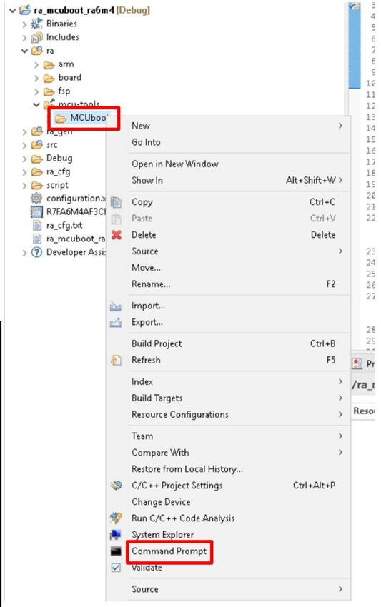
dependencies required for the script to work. Navigate to the ra_mcuboot_ra6m4>ra>mcu-
tools>MCUboot folder in the Project Explorer and select Command Prompt. This will open a command
window with the path set to the \mcu-tools\MCUboot folder.
R11AN0497EU0100 Rev.1.00 Page 15 of 51
May.12.2021Renesas RA Family Using MCUboot with RA Family MCUs
Figure 15. Open the command prompt
We recommend upgrading pip prior to installing the dependencies. Enter the following command to update
pip:
python -m pip install --upgrade pip
Next, in the command window, enter the following command line to install all the MCUboot dependencies:
pip3 install --user -r scripts/requirements.txt
This will verify and install any dependencies that are required.
3.2.4 Compile all the projects
For each project, open the configuration.xlm file, click Generate Project Contents and then click
to build the project. For the application projects (items 2 to 5), the post-build command will also sign the
corresponding images. The signed image for the application project is located under the \Debug folder and
is named _signed.bin (For example,
/app_ra6m4_s_primary/Debug/app_ra6m4_s_primary_signed.bin)
1. ra_mcuboot_ra6m4
2. app_ra6m4_s_primary
3. app_ra6m4_ns_primary
4. app_ra6m4_s_secondary
5. app_ra6m4_ns_secondary
R11AN0497EU0100 Rev.1.00 Page 16 of 51
May.12.2021Renesas RA Family Using MCUboot with RA Family MCUs
3.2.5 Debug the Applications
Choose to debug from the Secure project app_ra6m4_s_primary. This is required as otherwise the IDAU
region will not be set up correctly.
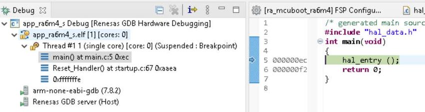
Right click on project app_ra6m4_s_primary and select Debug As > Renesas GDB Hardware
Debugging. The debugger should hit the reset handler in the bootloader. Note the address is in the
bootloader image.
Figure 16. Start the Application Execution
3.2.6 Download the Secure Image
At this point, only the bootloader image has been downloaded to flash and the IDAU has been set up for the
TrustZone settings. Now load the app_ra6m4_ns_primary and app_ra6m4_s_primary images using
the Load Ancillary File button. On the top of the e2 studio toolbar, click the Icon, then browse the secure
project signed image \Debug\app_ra6m4_s_primary_signed.bin file.
Figure 17. Click the Load Ancillary File button
Check the Load as raw binary image and set the address to 0x20000. Press OK to download the image.
Figure 18. Configure the Download Address of the Secure Image for Overwrite Update mode
3.2.7 Download the Non-Secure Image
Now load the app_ra6m4_ns_primary image using the same method as in the prior steps and set the
Address to 0x30000. Click OK to download the image.
R11AN0497EU0100 Rev.1.00 Page 17 of 51
May.12.2021Renesas RA Family Using MCUboot with RA Family MCUs
Figure 19. Load the Primary Non-Secure Application Image for Overwrite Update mode
Click Resume to run the project.
The program should now be paused in main at the hal_entry() call in the bootloader.
Figure 20. Start the Application Execution
Click to run again. The LEDs on the EK-RA6M4 should now be blinking while running in the non-secure
app.
Press the to pause the program. Note that the program counter is in the non-secure image. Click to
run again.
3.2.8 Open the J-Link RTT Viewer and Set Up Configurations
Figure 21. Configure the RTT Viewer
R11AN0497EU0100 Rev.1.00 Page 18 of 51
May.12.2021Renesas RA Family Using MCUboot with RA Family MCUs
Click OK and observe the output on the RTT Viewer. This output shows the Primary application is being
executed and all three LEDs are blinking.
Figure 22. Execution of Primary Non-Secure Application for Overwrite Mode
3.2.9 Downloading and Running the Secondary Applications
During development, the user can use the Ancillary loading capability to load the new secure image to the
intended location. The user can use the example new secure application provided in this application and
follow the steps below to perform an application upgrade.
1. Press the to pause the program.
2. Load the new application images to the secondary slot region using the Ancillary loading capability from
e2 studio.
Figure 23. Load the Secondary Secure Application Image for Overwrite Update Mode
Figure 24. Load the Secondary Non-Secure Application Image for Overwrite Update Mode
3. Click Resume . The overwrite will happen and the new image will be executed. The blue and green
led will be blinking instead of the all the LEDs.
4. Reconnect the J-Link RTT Viewer. Click File > Connect.
R11AN0497EU0100 Rev.1.00 Page 19 of 51
May.12.2021Renesas RA Family Using MCUboot with RA Family MCUs
Figure 25. Reconnect the J-Link RTT Viewer
5. Confirm the same configuration as shown in Figure 21, then click OK. Below output will be printed and
only the blue and green LEDs are blinking.
Figure 26. Executing the Secondary Non-Secure image for Overwrite Update Mode
3.2.10 Non-Secure Secondary image can be updated independent of the secure secondary
image
This step is provided as a reference for user to consider implementation of individual image update when
designing in a TrustZone environment.
Click Pause again and download the Primary Non-Secure application to the Secondary Non-Secure slot
using the Load Ancillary File tool. Click OK. Click Resume again. The three LEDs will start to blink again
and the RTT Viewer will show the same message as Figure 45.
• For Overwrite update mode, so long as the secondary image is marked for update, overwrite always
happens.
• It is possible to update the Secure and Non-Secure applications individually with proper application
design.
Figure 27. Load the Primary Non-Secure Image to the Second Slot
3.3 Running the EK-RA6M4 Example Project with Swap Update Modes
The process of running the EK-RA6M4 Swap Update Modes are similar to the Overwrite Update mode. This
section will focus on the difference in the operation.
R11AN0497EU0100 Rev.1.00 Page 20 of 51
May.12.2021Renesas RA Family Using MCUboot with RA Family MCUs
1. Follow section 3.2 step 3.2.1 to initialize the RA6M4 MCU. This step must be run prior to running the
MCUboot Module based applications.
2. Import the project under folder \ra6m4_swap_with_bootloader to a workspace and see the following
set of example projects.
Figure 28. Example projects for RA6M4 Swap Update Mode
The bootloader project ra_mcuboot_ra6m4 has similar functionality as the bootloader with Overwrite
Update mode introduced in section 3.2 step 3.2.4 except that the memory map definition and application
image update mode are different.
We recommend referring to Figure 61 for the Flash Layout of the system. Make a note of the starting
address of the various memory regions (Secure Primary, Non-Secure Primary, Secure Secondary, Non-
Secure Secondary). These addresses are used in the walk-through execution described in this section.
The functionalities of the application projects are same as the Overwrite update mode application
projects (demonstrated in section 3.2) except that the post build commands are different and signaling
the bootloader for Swap Update Mode.
3. Configure the Python Signing Environment by following section 3.1 and section 3.2 step 3.2.3 if this is
the first time you are signing the application image.
4. Compile the example projects in the same order as the Overwrite update mode by referencing section
3.2 step 3.2.4.
5. Follow section 3.2 step 3.2.5 to start debugging the application.
6. Follow section 3.2 step 3.2.6 to download the Primary Secure image but with a different destination
address as shown below.
Figure 29. Download the Primary Secure Image for Swap Update mode
R11AN0497EU0100 Rev.1.00 Page 21 of 51
May.12.2021Renesas RA Family Using MCUboot with RA Family MCUs
7. Follow section 3.2 step 3.2.7 to download the Primary Non-Secure image but with a different destination
address as shown below.
Figure 30. Download the Primary Non-Secure Image for Swap Update mode
8. Open the J-Link RTT Viewer and set up following configuration.
Figure 31. Configure the RTT Viewer for RA6M4 Swap Update Mode Projects
Click OK and observe the following output on the RTT Viewer. This output shows the Primary application
is being executed and all three LEDs are blinking.
Figure 32. Execution of Primary Non-Secure Application for Swap Update Mode
R11AN0497EU0100 Rev.1.00 Page 22 of 51
May.12.2021Renesas RA Family Using MCUboot with RA Family MCUs
9. Downloading and Running the Secondary Applications.
During development, the user can use the Ancillary loading capability to load the new Secure image to
the intended location. User can use the example new Secure application provided in this application and
follow the steps below to perform an application upgrade.
1. Press the button to pause the program.
2. Load the new application images to the secondary slot region using the Ancillary loading capability
from e2 studio.
Figure 33. Load the Secondary Secure Application Image for Swap Update Mode
Figure 34. Load the Secondary Non-Secure Application Image for Swap Update Mode
3. Click Resume . The swap will happen, and the new image will be executed. Only the blue and
green LEDs will be blinking.
4. Reconnect the J-Link RTT Viewer. Click Connect.
Figure 35. Reconnect the J-Link RTT Viewer
R11AN0497EU0100 Rev.1.00 Page 23 of 51
May.12.2021Renesas RA Family Using MCUboot with RA Family MCUs
5. Confirm the same configuration as shown in Figure 21, then click OK.
Figure 36. Executing the Secondary Non-Secure image for Swap Update Mode
10. Reset the application by clicking and notice that there is no swap happening and the Primary Image
is not swapped back. The secondary image is still executed.
11. Update the post build command for the Secondary application images to signal the bootloader that the
images are test images.
1. Update the post build command to remove --confirm and add --pad as shown in Figure 37 for
both the Secondary Secure and Secondary Non-Secure project.
Figure 37. Update the Post Build Command to Allow Image Testing
2. For the Secondary Secure and Secondary Non-Secure application project, do Project Clean and
then recompile the projects in the order of Secondary Secure project and then Secondary Non-
Secure project.
3. Initialize the MCU following instructions in step 1.
4. Follow step 5 to step 10 to run the application again. Notice that when the application is reset by
clicking , the Primary image will be swapped with the secondary image again. The primary image
is now executed.
3.4 Running the EK-RA6M3 Example Projects with Overwrite Update Modes
Follow the steps below to run the example projects for EK-RA6M3 using the MCUboot Overwrite Only
Update mode.
3.4.1 Import the projects under folder \ra6m3_overwrite_with_bootloader to a
workspace
The following example projects are included in this folder.
Figure 38. Example projects for RA6M3 Overwrite Update Mode
• Project ra_mcuboot_ra6m3 is the bootloader project
• Project app_ra6m3_primary is the initial primary application project. This project blinks the three
LEDs on the EK-RA6M3 kit
• Project app_ra6m3_secondary is the secondary application project. This project blinks the blue LED
on the EK-RA6M3 kit.
3.4.2 Configure the Python Signing Environment
Follow section 3.1 and section 3.2 step 3.2.3 if this is the first time you are signing the application image.
R11AN0497EU0100 Rev.1.00 Page 24 of 51
May.12.2021Renesas RA Family Using MCUboot with RA Family MCUs
3.4.3 Compile the projects
For each project, open the configuration.xlm file, click Generate Project Contents, and then click
to build the project. For the application projects, the post-build command will also sign the corresponding
images. The signed image is located under the \Debug folder and is name
_signed.bin (for example,
/app_ra6m3_primary/Debug/app_ra6m3_primary_signed.bin)
1. ra_mcuboot_ra6m3
2. app_ra6m3_primary
3. app_ra6m3_secondary
3.4.4 Initialize the MCU
Erase the entire MCU flash prior to proceeding to the following steps. This can be done using J-Link Flash
Lite. Launch J-Link Flash Lite and select the RA6M3, as shown in Figure 39.
Figure 39. Open J-Link Flash and Select RA6M3
Click OK and select Erase Chip at the next window.
Figure 40. Erase RA6M3
The entire flash will be erased if there are no permanently locked down sections.
3.4.5 Start the debug session from the Primary application
Right click on project app_ra6m3_primary and select Debug As > Renesas GDB Hardware Debugging.
The debugger should be at the reset handler in the bootloader. Note the address is in the bootloader image.
Figure 41. Start the RA6M3 Application Execution
3.4.6 Download the Primary image
On the top of the toolbar, press the Load Ancillary File Icon . Then click Workspace and select the
signed Primary application image. Check the Load as raw binary image and set the address to 0x10000.
Press OK to download the image.
R11AN0497EU0100 Rev.1.00 Page 25 of 51
May.12.2021Renesas RA Family Using MCUboot with RA Family MCUs
Figure 42. Select the Signed Primary Application Image and Configure the Download Address
Click Resume to run the project.
The program should now be paused in main at the hal_entry() call in the bootloader.
Figure 43. Run to the bootloader hal_entry function
Click Resume to run again. The LEDs on the EK-RA6M3 should now be blinking while the EK-RA6M3
is running in the Non-Secure app.
Press to pause the program. Note that the program counter is in the Primary image.
1. Open the J-Link RTT Viewer and set up the following configuration.
Figure 44. Configure the RTT Viewer for RA6M3 Project
R11AN0497EU0100 Rev.1.00 Page 26 of 51
May.12.2021Renesas RA Family Using MCUboot with RA Family MCUs
Click OK and observe the following output on the RTT Viewer. This output shows the Primary application is
being executed and all three LEDs are blinking.
Figure 45. Execution of Primary Application for Overwrite Mode
3.4.7 Downloading and Running the Secondary Applications
During development, the user can use the Ancillary loading capability to load the new Secure image to the
intended location. Follow the steps below to perform an application upgrade.
1. Press to pause the program.
2. Load the new application images to the secondary slot region using the Ancillary loading capability from
e2 studio. Select Load as raw binary image and configure the address to 0x30000.
Figure 46. Load the Secondary Application Image for Overwrite Mode
3. Click Resume . The overwrite will happen and the new image will be executed. Now only the Blue
LED will be blinking.
4. Reconnect the J-Link RTT Viewer. Click File > Connect.
Figure 47. Reconnect the J-Link RTT Viewer
5. Confirm the same configuration as shown in Figure 44, then click OK. The following output will be printed
and only the blue LED will blink.
Figure 48. Executing the Secondary Application Image for Overwrite Update Mode
R11AN0497EU0100 Rev.1.00 Page 27 of 51
May.12.2021Renesas RA Family Using MCUboot with RA Family MCUs
3.5 Updating the EK-RA6M3 Example Projects from Overwrite to Swap Update
Mode
Follow the steps below to convert the Overwrite Update mode base projects to use Swap Update mode.
1. Update the Upgrade Mode and scratch area as the following:
Figure 49. Update to Swap Mode
2. Update the application image signing command. For details on how to generate the signing command,
refer to section 5.3. Copy below signing command and paste the command to the Primary and
Secondary application post build command.
arm-none-eabi-objcopy -O binary ${ProjName}.elf ${ProjName}.bin & python
${workspace_loc:ra_mcuboot_ra6m3}/ra/mcu-tools/MCUboot/scripts/imgtool.py sign -k
${workspace_loc:ra_mcuboot_ra6m3}/ra/mcu-tools/MCUboot/root-ec-p256.pem --version 1.0.0+0
--header-size 0x80 --align 128 --max-align 128 --slot-size 0x20000 --max-sectors 4 --
confirm --pad-header ${ProjName}.bin ${ProjName}_signed.bin
Figure 50. Signing Command for Swap Update Mode
3. Edit the project Properties for the app_ra6m3_primary (and app_ra6m3_secondary) project and
navigate to the C/C++ Build>Settings. Click on the Build Steps tab and paste the command lines that
you copied from Figure 50 into the Post-build steps > commands and press Apply and Close. Make
sure do this for both Primary and Secondary projects.
R11AN0497EU0100 Rev.1.00 Page 28 of 51
May.12.2021You can also read