2021 DETASSELER TOOL BAR (DTB) OPERATOR'S MANUAL 493884
←
→
Page content transcription
If your browser does not render page correctly, please read the page content below
5 - DASH / AUTO

2021 DETASSELER TOOL BAR (DTB)
      OPERATOR’S MANUAL
            493884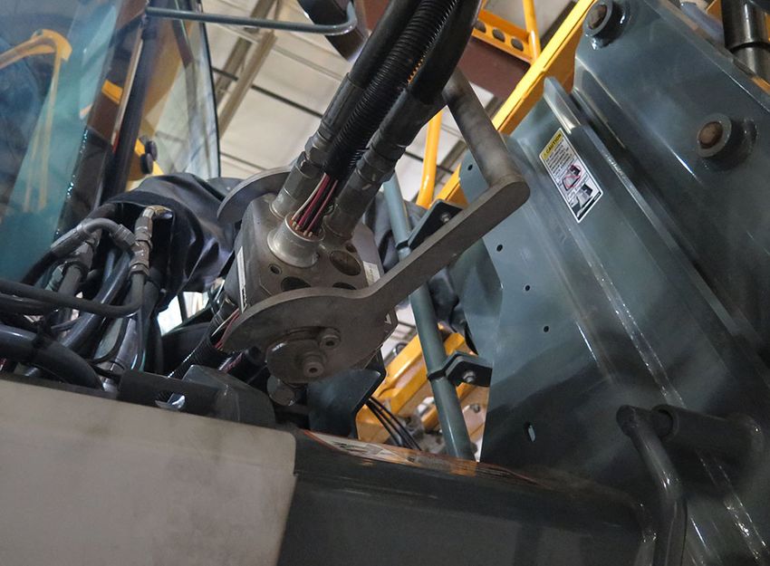
5 - DASH / AUTO
CONTENTS

1 – INTRODUCTION
    A Word From Hagie Manufacturing Company ...................................................................1-1
    About This Manual .............................................................................................................1-1
    Safety Messages Used In This Manual .............................................................................1-2
    Service and Assistance ......................................................................................................1-2
    Product Warranty ...............................................................................................................1-3
    Identification .......................................................................................................................1-3
    Specifications .....................................................................................................................1-4
2 – SAFETY AND PRECAUTIONS
    Intended Use ......................................................................................................................2-1
    Safety Precautions .............................................................................................................2-1
    Operator Presence Switch (OPS) ......................................................................................2-3
    Safety Decals .....................................................................................................................2-4
3 – OPERATING YOUR DTB
    Detasseling System Components ......................................................................................3-1
    Fold Procedure - Detasseler Tool Bar ...............................................................................3-6
    Detasseling System - Operation ........................................................................................3-9
    Tasseltrol™ XL/LS System 12 .........................................................................................3-11
4 – MAINTENANCE AND STORAGE
    Service - Lubrication ..........................................................................................................4-1
    Service Intervals ................................................................................................................4-3

                                                                                                                                                5 - DASH / AUTO
    Storage ..............................................................................................................................4-4
5 – MISCELLANEOUS
    Transporting .......................................................................................................................5-1
    Quick-Tach System - Detasseler Tool Bar .........................................................................5-3
    Attachment Assembly ......................................................................................................5-10
    Troubleshooting ...............................................................................................................5-17

Covers Attachment Serial Numbers: DTB 21001-21500                                                                        Part No. 493884
© 2020 Hagie Manufacturing Company. Clarion, Iowa USA                                                                    Rev. 21A200601
Some of the material used in this manual may be the reproduced works of Deere & Co.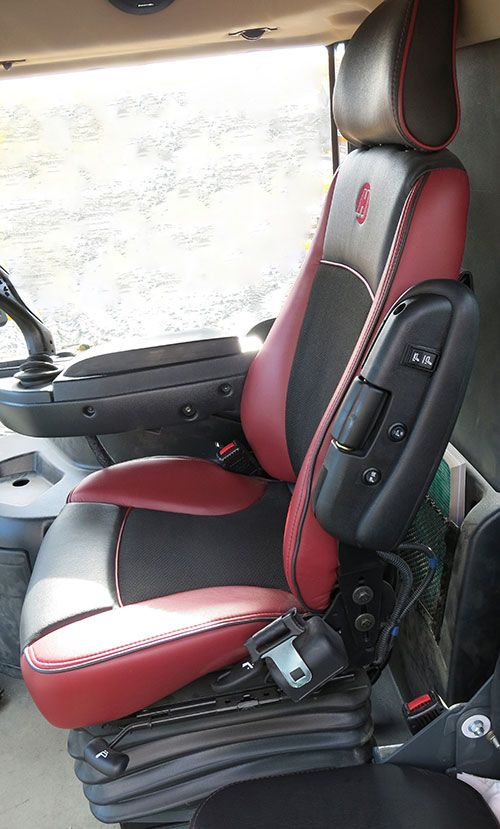
SECTION 1 – INTRODUCTION

A WORD FROM HAGIE                                    ABOUT THIS MANUAL
MANUFACTURING
COMPANY
    Congratulations on the purchase of your                        NOTICE
Detasseler Tool Bar (DTB) attachment! We
recommend that you review this operator’s              The purpose of this manual is to guide
manual and become familiar with operating              you in the proper operation of the DTB
procedures and safety precautions before               attachment, as well as provide you with
attempting to operate your DTB.                        pertinent safety precautions and
    As with any piece of equipment, certain            maintenance information. This manual is
operating procedures, service, and                     intended to cover the DTB attachment
maintenance are required to keep your DTB              only and any differences in the operation
in top running condition. We have attempted            of the sprayer controls. Refer to your
herein to cover all of the adjustments                 sprayer operator’s manual and all other
required to fit varying conditions. However,           literature that is included with the
there may be times when special care must              machine for complete instructions on
be considered.                                         machine operation.
NOTE: The user is responsible for
        inspecting the attachment and

                                                                   NOTICE
        having parts repaired or replaced
        when continued use of the product
        causes damage or excessive wear to
        other parts.                                   Any pictures or illustrations contained
   Hagie Manufacturing Company reserves                within this manual that depict situations

                                                                                                        5 - DASH / AUTO
the right to make changes in the design and            with shields, guards, rails, or lids
material of any subsequent DTB without                 removed are for demonstration only.
obligation to existing attachments.                    Keep all shields and safety devices in
   Thank you for choosing a Hagie DTB and              place at all times.
we ensure you of our continued interest and
support in its optimal performance for you.
                                                         This manual will aid you in the proper
We are proud to have you as a customer!
                                                     operation and service of your DTB
                                                     attachment. It is the responsibility of the user
                                                     to read the operator’s manual and comply
                                                     with the correct and safe operating
                                                     procedures, as well as maintain the product
                                                     according to the service information provided
                                                     in the Maintenance and Storage Section
                                                     elsewhere in this manual.
                                                         Photographs and illustrations used in this
                                                     manual are of general nature only. Some of
                                                     the equipment described and/or shown may
                                                     or may not be available on your attachment.

                                               1-1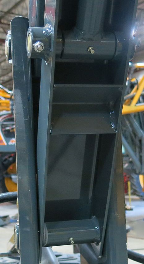
SECTION 1 –
                                                                              INTRODUCTION
    Information described in this manual was
correct at the time of printing. Because of
Hagie Manufacturing Company’s continuous
product improvement, certain information                             CAUTION
may not be included in this manual. To obtain
the most current operator’s manual for your              The signal word CAUTION indicates a
attachment, please visit www.hagie.com.                  hazardous situation which, if not
    Keep this manual in a convenient place               avoided, could result in minor or
for easy reference. This manual is                       moderate injury. CAUTION may also be
considered a permanent fixture of the                    used to alert against unsafe practices
product. In the event of resale, this manual             associated with events which could lead
must accompany the DTB.                                  to personal injury.
    If you do not understand any part of this
manual or require additional information or
service, contact your local John Deere dealer
for assistance.                                                     NOTICE
                                                         The signal word NOTICE indicates
                                                         operator awareness which, if not
SAFETY MESSAGES USED                                     avoided, may result in personal or
IN THIS MANUAL                                           property damage.
   The following safety messages found
throughout this manual alert you of situations         NOTE: A “Note” is intended to make special
that could become potentially dangerous to                   mention of, or remark on.
the operator, service personnel, or
equipment.
                                                       SERVICE AND ASSISTANCE
                DANGER
  The signal word DANGER indicates a
  hazardous situation which, if not
  avoided, will result in death or serious
  injury.

               WARNING
  The signal word WARNING indicates a                  John Deere Is At Your Service
  hazardous situation which, if not
  avoided, could result in death or serious               Customer satisfaction is important to
  injury.                                              Hagie and John Deere. Our dealers strive to
                                                       provide you with prompt, efficient parts and
                                                       service:
                                                       • Maintenance and service parts to sup-
                                                          port your equipment.

                                                 1-2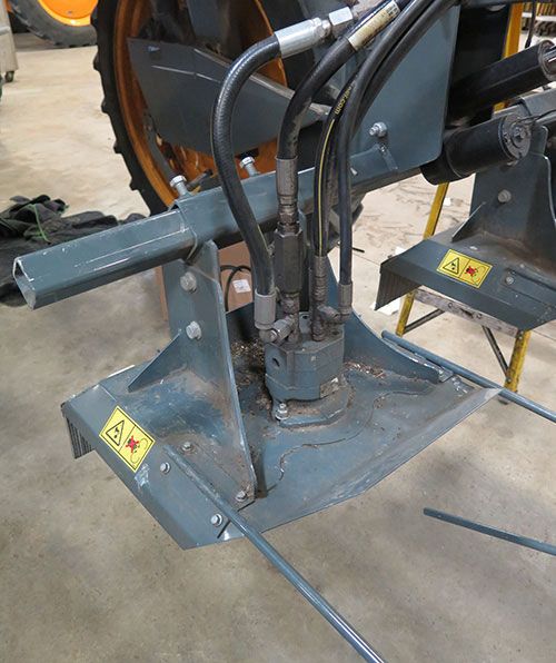
SECTION 1 –
INTRODUCTION
•    Trained service technicians and the nec-              The DTB attachment has an identification
     essary diagnostic and repair tools to ser-         plate mounted on the main tool bar that
     vice your equipment.                               provides attachment model and serial
                                                        number.
Customer Satisfaction Problem
Resolution Process
   Your John Deere dealer is dedicated to
supporting your equipment and resolving any
problem you may experience.
1. When contacting your dealer, be pre-
   pared with the following information:
   - Machine model and product identifica-
                                                                  DTB Identification Plate
   tion number.
                                                                      -Typical View
   - Date of purchase.
   - Nature of problem.
2. Discuss problem with dealer service
   manager.
3. If unable to resolve, explain problem to
   dealership manager and request assis-
   tance.
4. If you have a persistent problem your
   dealership is unable to resolve, ask your
   dealer to contact John Deere for assis-
   tance, or contact the Ag Customer Assis-
   tance Center at 1-866-99DEERE (866-
   993-3373) or e-mail us at
   www.deere.com/en_US/ag/contactus.                         DTB Identification Plate Location
                                                              (Located on the main tool bar)
                                                                      -Typical View

PRODUCT WARRANTY
  Please contact your local John Deere
dealer for further information.

IDENTIFICATION

               NOTICE
    Reference to right and left-hand used
    throughout this manual refers to the
    position when seated in the operator’s
    seat facing forward.

                                                  1-3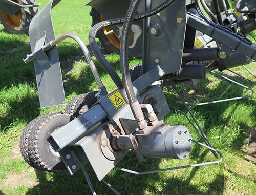
SECTION 1 –
                                                                                     INTRODUCTION

                                       SPECIFICATIONS
NOTE: Dimensions may vary, depending on tire size.
NOTE: Refer to “Specifications” provided in the machine operator’s manual for complete
      machine dimensions.

            B

                           A
                                                      C

 Detail                    Description                                       Specification
 A         Tool Bar Length                                   • 80.5”/204.5 cm (6 Row)
           (from front of tool bar to center of wheel hub)   • 128.5”/326.4 cm (8-10 Row)
                                                             • 186.5”/473.7 cm (12-18 Row)

 B         Height (from bottom of tool bar to ground)        75.75”/192.4 cm *

 C         Overall Machine Length                            •   315.5”/801.4 cm (6 Row, Short Frame)
           (from front of tool bar to rear hood)             •   341.5”/867.4 cm (6 Row, Long Frame)
                                                             •   363.5”/923.3 cm (8-10 Row, Short Frame)
                                                             •   389.5”/989.3 cm (8-10 Row, Long Frame)
                                                             •   421.5”/10 m (12-18 Row, Short Frame)
                                                             •   447.5”/11 m (12-18 Row, Long Frame)

 D         Overall Width (boom cradles)                      153”/388.6 cm

* Refer to “Tire Specifications” provided in the machine operator’s manual for a complete listing of tire
options when configuring specifications on your model.

                                                    1-4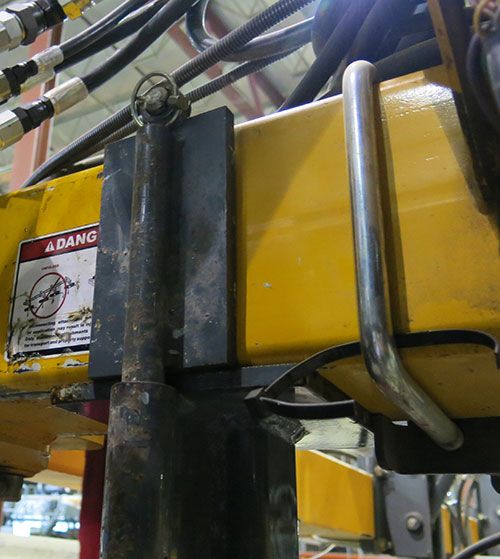
SECTION 1 –
INTRODUCTION

                       D

General Information

               NOTICE
    Because Hagie Manufacturing
    Company offers a variety of options, the
    illustrations in this manual may show a
    machine equipped other than standard.
    Machine dimension and weight values
    may vary, depending on available
    equipment.

•    Frame Type: 4x8” (10.2x20.3 cm)
     modular platform frame
•    Suspension: 4-wheel, individual, auto
     air-ride
•    Shipping Width:
     153”/388.6 cm (90/100’ boom cradles)
•    Approximate Dry Weight:
     3,204 lbs./1,453 kg (8-10 row tool bar)

                                               1-5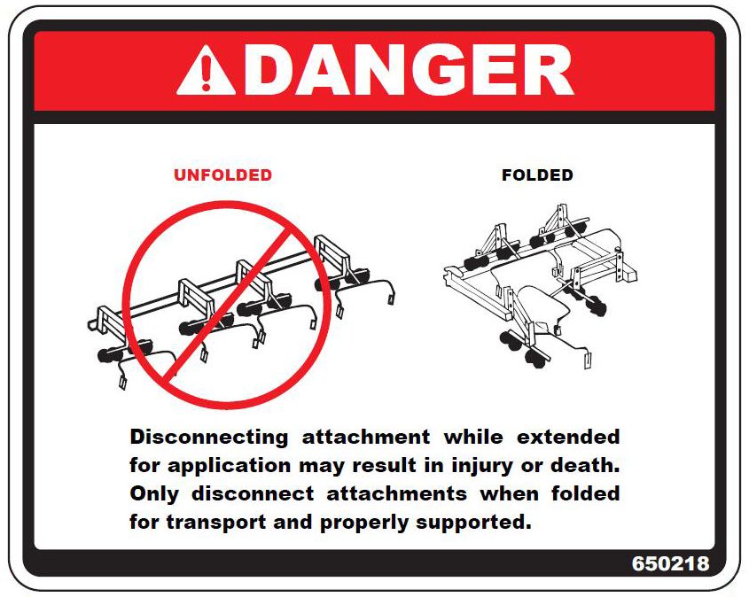
SECTION 1 –
                                                                      INTRODUCTION

            Description                            Specification
General
Monitors/Controls          Machine Display (Tasseltrol™ XL)

General System             Light sensing system, depth command, electrical disconnect,
                           hydraulic couplers

Outriggers
12-Row                     134”/340.4 cm (1 left, 1 right)

8-Row                      75”/190.5 cm (1 left, 1 right)

Quad Pullers
Number of Rows Available   6, 8, 10, or 12

Drive                      Hydraulic

Tire Size                  4.10/3.50 2-ply

Tire Pressure              10 PSI/.7 bar

Operating Speed            • Min Speed = 375 RPM
                           • Mid Speed = 400 RPM
                           • Max Speed = 425 RPM
                           NOTE: It is recommended to set the quad pullers as close to “mid”
                                   speed range as possible.

Pulling Height             • Minimum Range = 32-97” (81.3-246.4 cm)
                           • Maximum Range = 40-105” (101.6-266.7 cm)

Weight (per assembly)      86 lbs. (39 kg)

Cutter Heads
Number of Rows Available   6, 8, 10, or 12

Drive                      Hydraulic

Blade Size                 18”/45.7 cm

Operating Speed            • Min Speed = 2900 RPM
                           • Mid Speed = 3000 RPM
                           • Max Speed = 3100 RPM
                           NOTE: It is recommended to set the cutter heads as close to “mid”
                                   speed range as possible.

Cutting Height             • Minimum Range = 29-94” (73.7-238.8 cm)
                           • Maximum Range = 13-102” (33-259.1 cm)

Weight (per assembly)      62 lbs. (28 kg)

                                    1-6
SECTION 2 – SAFETY AND PRECAUTIONS

INTENDED USE                                           SAFETY PRECAUTIONS
                                                       General Safety
             NOTICE                                    •   Before operating the attachment, ensure
                                                           there are no obstacles or persons in the
  This attachment is designed for and                      path of travel.
  intended to be used for the removal of               •   Keep clear of all moving parts and keep
  tassels from the tops of corn plants. Use                others away while operating.
  in any other way or for any other purpose            •   The hydraulic and electrical control sys-
  is considered misuse of this attachment.                 tems are optimized for use with this
                                                           attachment. Any modification to these
                                                           systems may lead to unintended or
    Most accidents occur as the result of                  uncontrolled motion. Do NOT install add-
failure to follow basic and fundamental safety             on control systems that are not approved
rules and precautions. Recognizing potential               by Hagie Manufacturing Company.
safety hazards, following correct and safe             •   Some conditions cannot be completely
operating procedures described in this                     safeguarded against without interfering
manual, and complying with safety warnings                 with efficient operation of the machine
located throughout the machine and                         and/or reasonable accessibility. In these
attachment may reduce the risk of accidents.               cases, decals have been installed to pro-
    There is no way to completely eliminate                vide the operator with hazard informa-
the potential for danger when operating                    tion. Do NOT remove decals for any
agricultural equipment. Therefore, you must                reason. If a decal is damaged or miss-
study this operator’s manual and understand                ing, contact your local John Deere
                                                           dealer for replacement.

                                                                                                       5 - DASH / AUTO
how to operate the attachment controls for
safe operation before using the attachment.
Likewise, never let anyone operate the
attachment without proper instruction.
    Do not operate the attachment for
anything other than its intended use. Hagie
Manufacturing Company shall not be liable
for any damage, injury, or death associated
with improper use of the attachment.
    Do not make any modifications such as,             Wear Protective Clothing
but not limited to, weldments, add-ons,
adaptations, or changes from the original              •   Do not wear loose fitting clothing that
design of the attachment. Such modifications               could get caught in moving parts. Wear
may become safety hazards to you and                       safety equipment that is appropriate for
others and will void all warranties.                       the job.
    Replace missing, faded, or damaged
safety signs. Refer to “Safety Decals”
elsewhere in this section for correct sign and
placement.

                                                 2-1
SECTION 2 –
SAFETY AND PRECAUTIONS
• Disconnect the battery ground cable and
turn the Battery Disconnect Switch OFF
before servicing the electrical system or
welding on the attachment.
• Do not store chemical-soaked clothing in
the cab. Clean off as much mud and dirt
from your shoes as you can before
entering the cab.
Remove Accumulated Crop
Protect Against Noise Debris
• Wear suitable hearing protection. Pro- • The buildup of crop debris in the engine
longed exposure to loud noise may compartment, on the engine, or near
result in loss of hearing. moving parts is a fire hazard. Check and
clean areas frequently. Before performing
any inspection or service, engage the
parking brake, shut off the engine, and
remove the key.
Be Prepared
• Be prepared for an emergency. Keep a
fire extinguisher, first aid kit, and clean
water in the cab at all times. Remove Paint Before Welding or
• Service the fire extinguisher regularly. Heating
• Keep an accurate inventory of supplies
in the first aid kit and dispose of any • Avoid toxic fumes and dust. Hazardous
items that have expired. fumes can be generated when paint is
heated by welding, soldering, or using a
torch.
General Maintenance Safety • Do not use chlorinated solvents in areas
• Turn off sprayer engine before checking, where welding will take place.
adjusting, repairing, lubricating, or clean- • Perform all work in an area that is well
ing any part of the attachment. ventilated to carry toxic fumes and dust
away.
2-2SECTION 2 –
SAFETY AND PRECAUTIONS
• Dispose of paint and solvents properly. This safety feature introduces an
electrical interlock that ensures that when the
Avoid Heating Near Pressurized operator is out of the cab, the operation of
these functions have stopped. This is
Lines achieved by using the OPS to prevent the
• Avoid torching, welding, and soldering cutter heads and quad pullers from operating
near pressurized hydraulic lines. Pres- if the operator is not seated in the operator’s
surized lines may accidentally burst seat for two (2) seconds.
when heat goes beyond the immediate
flame area.
Safe Hydraulic Maintenance
• Always practice personal safety when
performing service or maintenance on
the hydraulic system.
• Use caution when working around
hydraulic fluid under pressure. Escaping
fluid can have sufficient force to pene-
trate your skin, causing serious injury.
This fluid may also be hot enough to
burn.
Operator Presence Switch
(Located inside the operator’s seat)
-Typical View
When the operator leaves the operator’s
seat while the machine is running, a warning
message will appear on the Machine Display
to alert the operator to operate the machine
from seat.
• Always lower the load or relieve pres-
sure before repairing a hydraulic leak.
OPERATOR PRESENCE
SWITCH (OPS)
The Operator Presence Switch (located
inside the operator’s seat) protects the
operator from exposure to moving parts or
hazards when operating the detasseler
cutter heads and quad pullers.
2-3SECTION 2 –
SAFETY AND PRECAUTIONS
Decal Locations
650178
(2) Quick-Tach
Operator Out Of Seat Message
(Located on the Machine Display)
To Resume Operation
• Return to operator’s seat.
• Press OK on the Machine Display warn-
ing message.
• Depress the Main Motor Switch (located
on the Hydrostatic Drive Control Handle)
to resume operation.
650218
SAFETY DECALS (2) - One located on each end of combo
Decals warning you of avoidable danger attachment
are located on various parts of the
attachment and cab area. They are there for
your personal safety and protection. DO NOT
remove them. They will fracture upon
attempted removal and therefore, must be
replaced.
Following are locations of important safety
decals. Replace them if they are damaged or
missing. All safety decals, instructional
decals, or machine striping may be
purchased through your local John Deere
dealer.
To replace safety decals, ensure the
installation area is clean and dry and decide
on exact position before you remove the
backing paper.
2-4SECTION 2 –
SAFETY AND PRECAUTIONS
650258 HXE28534
(Located on each side of cutter head (Located on left-hand front cross
assemblies) member)
CAUTION 650379
SEVERING OF FINGERS OR HAND. (Located on right-hand cab window)
DO NOT PLACE FINGERS OR
HAND NEAR A MOVING CUTTER BLADE,
ATTEMPT TO STOP A MOVING CUTTER
BLADE, OR PERFORM MAINTENANCE
NEAR A MOVING CUTTER BLADE.
650259
(Located on mounting tube of each
quad puller head assembly)
CAUTION
RISK OF INJURY FROM ROTATING TIRES.
DO NOT PLACE FINGERS OR HAND NEAR
MOVING QUAD PULLER TIRES, DISLODGE A
WEDGED OBJECT FROM MOVING TIRES, OR
PERFORM MAINTENANCE NEAR MOVING TIRES.
650303
(Located on right-hand cab window)
2-5SECTION 3 – OPERATING YOUR DTB
DETASSELING SYSTEM A
COMPONENTS
The Detasseling System is a constantly
monitored and continuously adjusted
system. The cab-mounted Machine Display
monitor receives data from the photo light
sensors to determine cutting/pulling height.
The following information in this section
explains the detasseling components and
their operation. Read the following section
entirely before operating the Detasseling
System.
B
NOTICE
Attachment maintenance and repair,
including clearing blockages/unplugging
detasseler components should be
performed by qualified service D C
personnel only.
E
• (A) - Detasseler Tool Bar Attachment
5 - DASH / AUTO
• (B) - LS System 12/Depth Command
• (C) - LS Photo Light Sensors
• (D) - Cutter Heads
• (E) - Quad Pullers
• (F) - Machine Display
• (G) - All Up/Down Switch*
• (H) - Outrigger Fold Switches (Left/Right)
• (I) - Main Motor Switch
* The Lift Icon Buttons on the Machine Display “DTB
Lifts/Motors” screen may also be used to raise/lower F
all lifts simultaneously.
3-1SECTION 3 –
OPERATING YOUR DTB
G
H
H
I
LS System 12/Depth Command
-Typical View
LS Photo Light Sensors
The LS Photo Light Sensors detect crop
height and send a signal to the LS System
12/Depth Command, which controls
automatic height adjustment.
Detasseler Tool Bar Attachment
(DTB)
The DTB attachment paired with the STS
provides a high-clearance design along with
adjustable automatic height control to
perform timely detasseling of corn crops
when timing is critical. The DTB unites
functionality with customizable options to
provide a solution that suits the individual
needs of your operation.
LS Photo Light Sensor Assembly
-Typical View
DTB Attachment
(Shown with quad pullers)
-Typical View
LS System 12/Depth Command
The LS (Light Sensing) System 12/Depth
Command is an automatic height adjustment
system controlled by the Machine Display
inside the cab.
3-2SECTION 3 –
OPERATING YOUR DTB
Cutter Heads
CAUTION
SEVERING OF FINGERS OR HAND.
DO NOT PLACE FINGERS OR
LS Photo Lights (Upper/Lower) HAND NEAR A MOVING CUTTER BLADE,
-Typical View ATTEMPT TO STOP A MOVING CUTTER
BLADE, OR PERFORM MAINTENANCE
NEAR A MOVING CUTTER BLADE.
-Typical View
The hydraulically-driven Cutter Heads go
• The upper and lower LS Photo Lights through rows of corn and cut the tassels from
are equipped with LED lights (A, C, D, E) the top of corn plants.
that indicate operation status.
• The LT/DK (Light/Dark) Switch (A)
(located on the photo light sensor) Cutter Head Speeds
changes the activated condition of the
green LED from ON (LT) to OFF (DK). Min Speed = 2900 RPM
• The Sensitivity Adjustment Screw (B) Mid Speed = 3000 RPM
should always be set to MAXIMUM.
• The Yellow LED Light (C) indicates the Max Speed = 3100 RPM
power is ON.
• The Green LED Light (D) indicates out- NOTE: It is recommended to set the cutter
put energized (sending a signal to the heads as close to “mid” speed range
Tasseltrol™ XL system). as possible.
• The Red LED Light (E) indicates that the
photo light is receiving reflected signal.
3-3SECTION 3 –
OPERATING YOUR DTB
Quad Puller Speeds
Min Speed = 375 RPM
Mid Speed = 400 RPM
Max Speed = 425 RPM
NOTE: It is recommended to set the quad
pullers as close to “mid” speed range
Cutter Heads as possible.
-Typical View
Quad Pullers
Quad Pullers
-Typical View
CAUTION
RISK OF INJURY FROM ROTATING TIRES.
DO NOT PLACE FINGERS OR HAND NEAR
MOVING QUAD PULLER TIRES, DISLODGE A Machine Display
WEDGED OBJECT FROM MOVING TIRES, OR The Machine Display is the central control
PERFORM MAINTENANCE NEAR MOVING TIRES.
center of the machine. In addition, it is used
for programming detasseling heads to
control tool bar functions, such as:
NOTICE • Lift/Motor Control (Auto/Manual Mode)
• Depth Command
• Light Sensing
Ensure quad puller tires have equal
• Calibration
pressure. Check tire pressure daily.
NOTE: Maximum tire pressure =
10 psi (.7 bar).
The hydraulically-driven Quad Pullers go
through rows of corn and pull the tassels
from the top of corn plants by catching it
between the Quad Puller tires moving at high
speed in opposite directions.
3-4SECTION 3 –
OPERATING YOUR DTB
Machine Display
Lift Icon Buttons (All Up/Down)
-Typical View
(Located on the Machine Display
DTB Lifts/Motors Screen)
-Typical View
All Up/Down Switch
The All Up/Down Switch (located on the
Hydrostatic Drive Control Handle) is used to Outrigger Fold Switches
raise or lower all lifts simultaneously. In
addition, the same all up/down function can (Left/Right)
be controlled by pressing the Lift Icon The hydraulic Outrigger Fold Switches
Buttons - UP/DOWN (located on the Machine (located on the Hydrostatic Drive Control
Display “DTB Lifts/Motors” screen). Handle) are used to hydraulically fold/unfold
the outriggers.
All Up/Down Switch
Outrigger Fold Switches - Left/Right
(Located on the Hydrostatic
(Located on the Hydrostatic
Drive Control Handle)
Drive Control Handle)
-Typical View
-Typical View
3-5SECTION 3 –
OPERATING YOUR DTB
Main Motor Switch
FOLD PROCEDURE -
NOTE: The Main Motor Switch is used for
detasseling functions. This switch is DETASSELER TOOL BAR
referred to as the Master Spray
Switch when used for spray
application. Refer to your machine
operator’s manual for further WARNING
information.
The detasseling head motors are Before proceeding, check area around
controlled by the Main Motor Switch (located the machine for bystanders, overhead
on the Hydrostatic Drive Control Handle). objects, and power lines. Failure to
This switch must be in the ON position to comply may result in serious injury or
enable detasseling head operation. death.
Unfolding the Attachment
(From storage position)
1. Ensure the Hydrostatic Drive Control
Handle is in the NEUTRAL position.
Main Motor Switch
(Located on the Hydrostatic
Drive Control Handle)
-Typical View
Hydrostatic Drive Control Handle
-Typical View
2. Engage the parking brake.
3-6SECTION 3 –
OPERATING YOUR DTB
3. Start the engine. 6. If equipped with the 4-2 Detasseler
4. Press the Field/Road Button (located on Tool Bar, continue to press and hold the
the Machine Display “DTB Lifts/Motors” Outrigger Fold Switches to extend the
screen) and change the machine’s drive left and right-hand slide extensions.
state to FIELD.
4-2 Detasseler Tool Bar - if equipped
(Extended View)
Folding the Attachment
(To storage position)
NOTICE
Field/Road Button
(Located on the Machine Display 4-2 Detasseler Tool Bar Only
DTB Lifts/Motors Screen) Ensure the outer slide extensions are
fully retracted before folding the
5. Press and hold the corresponding Out- outriggers in. Failure to comply will result
rigger Fold Switch (located on the Hydro- in property damage.
static Drive Control Handle) in the OUT
(Unfold) position until outriggers fully
NOTICE
extend.
Stagger detasseling heads before
folding the outriggers. Failure to comply
will result in property damage. Refer to
“Transporting” in the Miscellaneous
Section elsewhere in this manual for
further information.
• Right
Outrigger
• Left OUT 1. Press the Attachment Button (located on
Outrigger the Machine Display Main Menu).
OUT
Outrigger Fold Switches - Left/Right
(Located on the Hydrostatic
Drive Control Handle)
-Typical View
3-7SECTION 3 –
OPERATING YOUR DTB
• Left • Right
Level Level
UP UP
• Right
• Left Level
Level DOWN
DOWN
Attachment Button
(Located on the Machine
Display Main Menu)
2. PREP TO FOLD - Press the Prep Button
(located on the Machine Display “DTB
Lifts/Motors” screen OR the “DTB Depth Level Switches - Left/Right
Command” screen). (Located on the Hydrostatic
Drive Control Handle)
-Typical View
NOTE: Once the tool bar is prepped to fold,
a “DTB Prep to Fold Complete”
message will appear on the display.
4. Press and hold the corresponding Out-
rigger Fold Switch (located on the Hydro-
static Drive Control Handle) in the IN
(Fold) position until outriggers fully
retract.
NOTE: If equipped with the 4-2
Detasseler Tool Bar, the left and
Prep Button right-hand slide extensions will
(Located on the Machine Display retract first, followed by the
DTB Lifts/Motors Screen or outriggers when the Outrigger
DTB Depth Command Screen) Fold Switches are depressed.
3. Press BOTH left and right-hand Level
Switches (located on the Hydrostatic
Drive Control Handle) either UP or
DOWN simultaneously.
The tool bar will then adjust the lifts and
the depth command actuators will posi-
tion to allow folding.
3-8SECTION 3 –
OPERATING YOUR DTB
• Left • Right
Outrigger Outrigger
IN IN
Machine Display
-Typical View
2. Ensure the Hydrostatic Drive Control
Handle is in the NEUTRAL position.
Outrigger Fold Switches - Left/Right
(Located on the Hydrostatic
Drive Control Handle)
-Typical View
DETASSELING SYSTEM -
OPERATION
Getting Started
1. Program the Tasseltrol™ XL system
through the Machine Display.
Refer to “Tasseltrol XL/LS System 12”
provided elsewhere in this section for
further information.
Hydrostatic Drive Control Handle
-Typical View
3. Engage the parking brake.
4. Start the engine.
3-9SECTION 3 –
OPERATING YOUR DTB
5. Press the Field/Road Button (located on
the Machine Display “DTB Lifts/Motors” • Motor Icon
screen) and change the machine’s drive Button
state to FIELD.
NOTE: The drive state of the machine
cannot be changed unless the
Hydrostatic Drive Control Handle is
in the NEUTRAL position (and
machine speed is less than 0.5 mph/
0.8 km/h).
Motor Buttons (1-6)
(Located on the Machine Display
DTB Lifts/Motors Screen)
8. Turn the Main Motor Switch (located on
the Hydrostatic Drive Control Handle)
ON.
NOTICE
Field/Road Button
(Located on the Machine Display If loss of hydraulic pressure occurs or the
DTB Lifts/Motors Screen) low hydraulic oil warning indicator
appears on the Machine Display, shut
6. Unfold and position tool bar to desired down the system immediately. Failure to
position. Refer to “Fold Procedure - comply may result in system damage
Detasseler Tool Bar” elsewhere in this and will void the warranty.
section for further information.
7. Press the corresponding Motor Button(s)
(located on the Machine Display “DTB
Lifts/Motors” screen) to turn desired
detasseling head motors ON.
NOTE: Press the Motor Icon Button (next to
the individual motor buttons) to
activate all motors.
3-10SECTION 3 –
OPERATING YOUR DTB
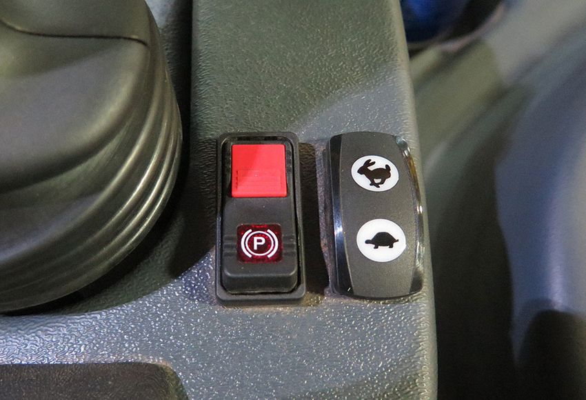
Throttle Switch
(Located near the Hydrostatic
Drive Control Handle)
-Typical View
10. Slowly move the Hydrostatic Drive Con-
Main Motor Switch trol Handle forward to obtain desired
(Located on the Hydrostatic ground speed.
Drive Control Handle)
-Typical View
TASSELTROL™ XL/LS
9. Press and hold the Throttle Switch
(located near the Hydrostatic Drive Con- SYSTEM 12
trol Handle) in the UP/“rabbit icon” posi- (Light Sensing/Depth Control)
tion to achieve the recommended RPM
to operate the detasseling head motors. Lifts/Motors
NOTE: Detasseling heads will be available Manual/Auto Mode
for immediate use by increasing
In MANUAL MODE, the lifts move
engine RPM.
manually, or not using the photoeyes to
adjust the lift height. In AUTO MODE, the lifts
will automatically raise if both photoeyes are
NOTICE covered, and lower if the bottom photoeye is
not covered.
Operating the Detasseling System
below the recommended engine RPM
(STS10/STS12 - 2400 RPM, STS14/
STS16 - 2200 RPM) will not provide the
system with adequate hydraulic oil flow
and may cause degraded or poor
performance.
3-11SECTION 3 –
OPERATING YOUR DTB
• Press Motor Buttons (1-6) (A) to turn
• Press the Attachment Button on the desired motor(s) on/off.
Main Menu to navigate to the “DTB • Press the M or A Button(s) (B) below the
Lifts/Motors” screen. corresponding lift number to enable
Manual or Auto mode.
• Press the Motor Icon Button (C) to acti-
vate all motors.
• Press the Auto Button (D) to enable
Manual or Auto mode for all lifts.
NOTE: This button will always say “AUTO”,
but will illuminate when all lifts are in
Auto mode.
• Press the “-” or “+” Buttons (E) to
increase/decrease depth command
height for all lifts.
NOTE: Press center of button (F) to set all
Attachment Button depth command actuators to desired
height.
• Press and Hold the desired Up or Down
E F E Arrow Button (G) below the correspond-
ing lift number to raise/lower the individ-
ual lifts.
A C • Press and Hold desired Lift Icon Button
B D (H) (UP or DOWN) to raise/lower all lifts
together.
NOTE: Same function can be done through
the All Up/Down Switch (located on
the hydrostatic drive control handle).
J
H • Press the Settings Button (I) to navigate
G to the “DTB Settings” screen.
I K
• Prep (Prep to Fold) - Press the Prep But-
DTB Lifts/Motors Screen ton (J), then press BOTH left and right-
(Manual Mode) hand level switches (located on the
hydrostatic drive control handle) either
up or down simultaneously. The tool bar
will then adjust the lifts and the depth
command actuators will position to allow
the main folds to be folded.
B
NOTE: If equipped with the 4-2 Detasseler
Tool Bar, there will be a 10 second
delay to allow the tool bar to retract.
NOTE: Once the tool bar is prepped to fold,
a “DTB Prep to Fold Complete”
message will appear on the display.
Complete the folding procedure by
pressing the corresponding left and
DTB Lifts/Motors Screen
right-hand Outrigger Fold Switches
(Auto Mode)
(located on the hydrostatic drive
control handle).
3-12SECTION 3 –
OPERATING YOUR DTB
• Press the Depth Command Button (K) to
navigate to the “DTB Depth Command”
screen. A B A
Depth Command C
F
• Press the “-” or “+” Buttons (A) to D G
increase/decrease depth command E
height for all lifts.
NOTE: Press center of button (B) to set all
depth command actuators to desired
height.
• 1-6 row (C) (lift number). H I J
• 0 row (D) (actual position of each depth
DTB Depth Command Screen
command actuator).
• Press the desired Up/Down Arrow But-
ton(s) (E) to raise/lower the correspond-
ing depth command actuators. Settings
• MEM (Memorize) (F) - Press the MEM • Lift Up Speed - Press the Auto, Manual,
Button to allow the system to remember or All Up Button to navigate directly to
the position of all photoeyes. the corresponding “DTB Lift Up” screen
• MR (Memory Recall) (G) - Press the MR to adjust lift speed for desired mode.
Button to allow the photoeyes to go back • All Up Time - Amount of time that the
to the previously memorized position. lifts will raise in the “All Up” state. Swipe
• Press the Settings Button (H) to navigate left or right to decrease/increase the
to the “DTB Settings” screen. amount of time (in 5 second intervals)
• Prep (Prep to Fold) - Press the Prep But- that the lifts will travel up after the All Up
ton (I), then press BOTH left and right- Switch (located on the hydrostatic drive
hand level switches (located on the control handle) is pressed momentarily.
hydrostatic drive control handle) either
NOTE: With a value of 0 seconds, the lifts
up or down simultaneously. The tool bar
will stop raising when the All Up
will then adjust the lifts and the depth
Switch is released.
command actuators will position to allow
the main folds to be folded. • Response Parameter - Time delay
between a change in the photoeye sta-
NOTE: If equipped with the 4-2 Detasseler tus until the lift responds. A higher num-
Tool Bar, there will be a 10 second ber means that the lift will wait longer
delay to allow the tool bar to retract. between a change in photoeye status
NOTE: Once the tool bar is prepped to fold, until that lift responds to the change.
a “DTB Prep to Fold Complete” Example: Time delay between bottom
message will appear on the display. photoeye being uncovered until that lift
Complete the folding procedure by moves down. Also, time delay between
pressing the corresponding left and the top photoeye being covered until that
right-hand Outrigger Fold Switches lift moves up.
(located on the hydrostatic drive • Bottom Parameter - Quickness of
control handle). response for lift to move down when the
• Press the Lift/Motors Button (J) to navi- bottom photoeye is uncovered. A higher
gate to the “DTB Lifts/Motors” screen. number means that the output will reach
the maximum auto speed for that lift
faster.
3-13SECTION 3 –
OPERATING YOUR DTB
• Top Parameter - Quickness of response
for lift to move up when the top photoeye
is covered. A higher number means that
the output will reach the maximum auto
speed for that lift faster.
• Auto One Tap - When this parameter is
enabled (swipe right to activate, or left to
deactivate) and the lift is in Auto mode,
that lift will lift up when the Lift Up Button
is pressed for that lift for the “All Up
Time”. To set the lift back to Auto mode,
press the All Up/Down Switch (located
on the hydrostatic drive control handle)
in the DOWN position, or the Auto But-
ton on the “DTB Lifts/Motors” screen. DTB Lift Up (Auto) Screen
• CAL - Press the Cal Button to navigate
to the “Calibration” screen.
DTB Lift Up (Manual) Screen
DTB Settings Screen
Lift Up (Auto)
• Each lift speed can be adjusted in Auto
mode. Swipe right to increase speed, or
left to decrease speed.
Lift Up (Manual)
Each lift speed can be adjusted in Manual
mode. Swipe right to increase speed, or left
to decrease speed.
Lift Up (All Up)
• Set All-Up speed for entire tool bar by DTB Lift Up (All Up) Screen
adjusting the “All-Up Speed” (last param-
eter). Swipe right to increase speed, or
left to decrease speed. Calibration
NOTE: Each lift can be offset from this • Sensor Calibration - Press Depth Com-
overall speed in order to match mand UP Button (A) to achieve lowest
speeds of the other lifts.
3-14SECTION 3 –
OPERATING YOUR DTB
position sensor reading, then press “Set
Min”.
• Press Depth Command DOWN Button
(B) to achieve highest position sensor
reading, then press “Set Max”.
• For lifts, move lifts to lowest position,
then press “Set Min”. Move lifts to high-
est position, then press “Set Max”.
Press and Hold desired Lift Icon Button
(C) UP or DOWN to raise/lower all lifts
together.
NOTE: Sensor calibration only needs to be
performed if a position sensor is
replaced or the position sensor is not
reading correctly.
A
B
C
DTB Calibration Screen
3-15SECTION 4 – MAINTENANCE AND STORAGE
SERVICE - LUBRICATION
NOTICE
Failure to properly lubricate pivot and
friction points may result in unnecessary
wear and damage.
Quad Puller Heads
• Lubricate each Quad Puller Head grease
zerk (4 - two each side) twice per day Outrigger Fold
(morning and noon suggested). -Typical View
Lift Arm Assemblies
• Lubricate each Lift Arm Assembly
grease zerk (6) a minimum of every 50
hours of operation, or as needed.
5 - DASH / AUTO
Quad Puller Head
-Typical View
Lift Arm Assembly - Top
Outrigger Fold (Left and Right) -Typical View
• Lubricate each left and right Outrigger
Fold grease zerk (2) a minimum of every
50 hours of operation, or as needed.
4-1SECTION 4 –
MAINTENANCE AND STORAGE
Lift Arm Assembly - Mid
-Typical View
Lift Arm Assembly - Inner Arm
-Typical View
NOTE: An additional grease zerk is located
inside of the lower lift arm frame.
4-2SECTION 4 –
MAINTENANCE AND STORAGE
SERVICE INTERVALS
Service Point Daily/Before Each Use 50 Hrs.
Check Quad Puller Tire Pressure X
Check/Tighten Cutter Blade Retaining Bolts X
Lubricate Quad Puller Head Grease Zerks X
Lubricate Outrigger Fold Grease Zerks X
Lubricate Lift Arm Assembly Grease Zerks X
4-3SECTION 4 –
MAINTENANCE AND STORAGE
STORAGE
Preparing For Storage
1. Perform daily and weekly lubrication and
maintenance inspections as required.
2. With the engine at normal operating tem-
perature, cycle all the hydraulic func-
tions.
3. Thoroughly wash the attachment and
touch up any chipped or damaged paint.
4. Replace any damaged or missing
decals.
NOTE: Contact your local John Deere
dealer for paint touch-up
recommendations and decal
replacement.
5. Apply multi-purpose grease to hydraulic
cylinder rods.
6. If the attachment will be stored sepa-
rately, ensure that all electrical and
hydraulic ends are capped or covered
with a suitable covering.
Removal From Storage
NOTICE
Protective compounds such as grease
can harden under exposure to weather
conditions. Be sure to remove any dried
grease and reapply new, if necessary.
1. Remove any dried grease from the cylin-
der rods and re-apply if necessary.
2. Thoroughly clean the attachment.
3. Carefully unseal any openings that were
sealed for storage.
4. Attach DTB to the sprayer and manually
cycle the hydraulics two or three times to
adequately lubricate components.
4-4SECTION 5 – MISCELLANEOUS
Folding the Outriggers
TRANSPORTING
Transporting Your Machine with
an Attachment NOTICE
Stagger detasseling heads before
WARNING
folding the outriggers. Failure to comply
will result in property damage.
When transporting the machine,
observe the following to avoid serious Before folding the outriggers, the
injury or death: detasseling heads must be staggered in
• Check for adequate clearance before height. Damage will occur if detasseling
driving under any overhead obstructions. heads are all the same height when the
• Contact with power lines may result in outriggers are folded.
serious injury or death.
To Stagger the Detasseling Heads
1. Press the Attachment Button (located on
the Machine Display Main Menu).
CAUTION
Ensure there is adequate clearance
when transporting the sprayer near an
object with clearance less than the
transporting height and width of the
5 - DASH / AUTO
overall machine and attachment.
CAUTION
Avoid collisions. Before transporting Attachment Button
machine on a public roadway, check and (Located on the Machine
follow local regulations regarding size Display Main Menu)
limits, the use of lights, flags, signs, pilot
vehicles, and other requirements for 2. PREP TO FOLD - Press the Prep Button
transporting loads using trailer. (located on the Machine Display “DTB
Lifts/Motors” screen OR the “DTB Depth
Command” screen).
5-1SECTION 5 –
MISCELLANEOUS
NOTE: Once the tool bar is prepped to fold,
a “DTB Prep to Fold Complete”
message will appear on the display.
Prep Button
(Located on the Machine Display
DTB Lifts/Motors Screen or
DTB Depth Command Screen) Staggered Detasseling Heads
-Typical View
3. Press BOTH left and right-hand Level
Switches (located on the Hydrostatic Alternatively, if manual detasseling head
Drive Control Handle) either UP or staggering is desired, perform Steps 4-6
DOWN simultaneously. through the Machine Display. Refer to
The tool bar will then adjust the lifts and “Tasseltrol™ XL/LS System 12” provided
the depth command actuators will posi- elsewhere in this manual for further
tion to allow folding. information.
4. Lower the two center detasseling heads
• Left • Right
Level
all the way DOWN.
Level
UP UP 5. Raise all the detasseling heads on one
side to approximately half of the fully
raised height.
6. Raise the detasseling heads on the
opposite side to the fully raised height.
To Fold the Outriggers
• Slowly fold the outriggers in, making
• Right adjustments (as necessary) to the height
• Left Level
Level DOWN
of the detasseling heads.
DOWN Refer to “Fold Procedure - Detasseler
Tool Bar” elsewhere in this manual for
further information.
NOTICE
Level Switches - Left/Right
(Located on the Hydrostatic Do not attempt to make any adjustments
Drive Control Handle) to the detasseling heads after the
-Typical View outriggers are folded. Failure to comply
may cause the stalk guides or depth
command sensor bars to entangle,
resulting in equipment damage.
5-2SECTION 5 –
MISCELLANEOUS
Transporting Machine Using 8. Secure the machine onto the trailer
using the recommended securement
Trailer restraints (see trailer manufacturer’s
Loading operation manual).
9. Cover or remove the SMV (Slow Moving
Vehicle) emblem when traveling over 25
mph (40 km/h).
WARNING Unloading
1. Pull the trailer to flat ground.
Keep all persons away from trailer when
2. Apply the pulling vehicle’s parking brake
loading or unloading the sprayer. Failure
and turn the engine OFF.
to comply may result in serious injury or
3. Use tire chocks to keep the trailer from
death.
moving.
4. Lower the trailer ramps and set ramp
spacing for the machine’s tread width
NOTICE setting.
5. Carefully release the securement
restraints.
Read and understand the trailer 6. Have an attendant help guide you off of
manufacturer’s operation manual. Hitch the trailer.
the trailer to the pulling vehicle according 7. Uncover or replace the SMV (Slow Mov-
to their recommendations. ing Vehicle) emblem.
NOTICE QUICK-TACH SYSTEM -
DETASSELER TOOL BAR
The loaded height and width of the trailer
must conform to state law in which it is
WARNING
being used. Do not exceed the trailer
manufacturer’s recommendations on
loaded weight.
When connecting or disconnecting the
attachment, observe the following safety
1. Pull the trailer to flat ground. precautions:
2. Apply the pulling vehicle’s parking brake • Monitor both sides of the attachment
and turn the engine OFF. during fold procedure.
3. Use tire chocks to keep the trailer from • Select a safe area that is solid and level
moving. before unfolding/folding the attachment.
4. Ensure the DTB outriggers are in the • Clear area of personnel.
fully retracted (folded) position. • Check for overhead obstructions.
5. Lower the trailer ramps and set ramp • Do not unfold or fold combo attachment
spacing for the machine’s tread width near power lines. Contact with power lines
can result in serious injury or death.
setting.
6. Have an attendant help guide you onto
the trailer.
7. Allow enough room between the
machine and the pulling vehicle for safe
turning.
5-3SECTION 5 –
MISCELLANEOUS
WARNING
Turn the engine OFF before connecting/
disconnecting any hoses or electrical
lines. Failure to comply may result in
serious injury or death.
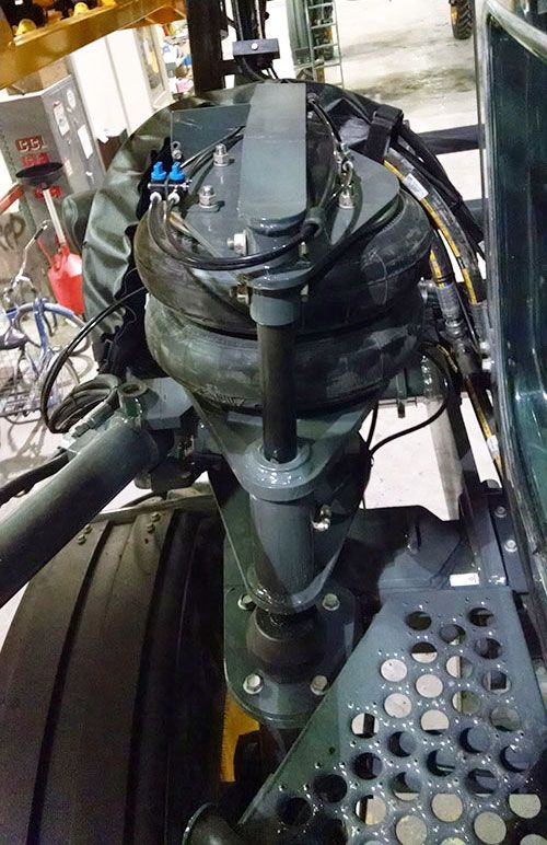
Connecting the Detasseler Tool
Bar Attachment
1. Square up to the DTB attachment.
2. Lower the machine by rotating the corre-
sponding Air Suspension Valves Lock Pin (2)
(located on the left-hand front air bag) in (Located on the front left and
the COUNTER-CLOCKWISE (Deflate) right-hand side of machine)
position. -Typical View
* Disengaged position shown
4. Slowly pull into the DTB attachment.
5. Ensure the Attachment Hooks are high
• Left- enough to clear the Mounting Pins.
Hand
• Right-
Hand
Air Suspension Valves Attachment Clearing Mounting Pin
(Located on the left-hand front air bag) -Typical View
-Typical View
6. Raise the machine and engage Attach-
3. Disengage the Quick-Tach Lock Assem- ment Hooks by rotating the correspond-
blies by pulling the Lock Pins (located on ing Air Suspension Valves in the
the front left and right-hand side of CLOCKWISE (Inflate) position.
machine) OUT as far as it will go until it
is in the “lock-out” position. NOTE: Raising the machine will allow the
weight of the attachment to pull the
NOTE: “Lock-out” position prevents re- Attachment Hooks over the Mounting
locking while attaching or detaching
the attachment.
5-4SECTION 5 –
MISCELLANEOUS
Pins. You will notice a change of Receptacle (located on left-hand side of
weight as the machine begins to machine), ensuring full engagement.
support the attachment.
7. Engage the Quick-Tach Lock Assem-
blies by pushing the Lock Pins IN, ensur-
ing full engagement.
• Quick
Connect
Handle
Hydraulic/Electric Multi-Coupler Assembly
(Left-hand side of machine shown)
11. Push the Quick Connect Handle OUT to
engage left-hand hydraulic/electrical
connections.
12. Press and hold the red Release Button
(located on the right-hand quick connect
handle) and lower handle into DOWN
position.
13. Remove the Hydraulic Connection Cover
(located on right-hand side of machine)
and set aside.
• Hydraulic
Connection
Cover
• Release
Button
Lock Pin (2)
-Typical View Hydraulic Connection Cover
* Engaged position shown and Release Button
(Right-hand side of machine shown)
8. Engage the parking brake. -Typical View
9. Turn the engine OFF before connect-
ing any hoses or electrical lines! 14. Install the Hydraulic Connection (located
10. Install the Hydraulic/Electric Connection on the right-hand side of DTB attach-
(located on the left-hand side of DTB ment) into the Multi-Coupler Receptacle
attachment) into the Multi-Coupler (located on right-hand side of machine),
ensuring full engagement.
5-5SECTION 5 –
MISCELLANEOUS
• Quick Connect
Handle
Hydraulic Multi-Coupler Assembly
(Right-hand side of machine shown) Stop Plate
-Typical View (Located on the inward side of
each DTB attachment stand)
15. Press and hold the red Release Button -Typical View
and push Quick Connect Handle UP to
engage right-hand hydraulic connec- 18. Remove the DTB attachment stands and
tions. set aside.
16. Remove the Securement Pins (located
on the inward side of each DTB attach-
ment stand) and set aside. Disconnecting the Detasseler
Tool Bar Attachment
NOTICE
Stagger detasseling heads before
folding the outriggers. Failure to comply
will result in property damage.
WARNING
Ensure DTB attachment is in the fully
Securement Pin FOLDED position before detaching from
(Located on the inward side of machine. Failure to comply may result in
each DTB attachment stand) serious injury or death and will result in
-Typical View property damage.
17. Remove the Stop Plate (located on the
inward side of each DTB attachment Before disconnecting the DTB
stand) and set aside. attachment, determine a proper storage
location. When choosing a place to store the
attachment, there are three important things
to keep in mind:
5-6SECTION 5 –
MISCELLANEOUS
Is the ground level?
The ground must be level to help prevent
the attachment from falling over. Level
ground will also minimize stress on the frame
of the attachment when in storage.
Is there enough space?
Be aware of the room that is needed for
the attachment and adequate space to travel
around it safely.
Is it accessible?
The attachment needs to be positioned so
you can connect easily. Ensure there is
enough room and that the attachment is not Attachment Button
blocked, or blocking other items. (Located on the Machine
If temporarily storing attachment on a soft Display Main Menu)
surface (such as grass), it is recommended
to place blocks or wood beneath each of the 2. PREP TO FOLD - Press the Prep Button
DTB attachment stands to prevent the (located on the Machine Display “DTB
attachment from sinking into the ground. Lifts/Motors” screen OR the “DTB Depth
Command” screen).
NOTE: It is NOT recommended to store the
attachment on a soft surface for an
extended period of time, due to the
risk of settling soil, even when blocks
or wood are used.
NOTICE
Stagger detasseling heads before
folding the outriggers. Failure to comply
will result in property damage.
Prep Button
1. Press the Attachment Button (located on (Located on the Machine Display
the Machine Display Main Menu). DTB Lifts/Motors Screen or
DTB Depth Command Screen)
3. Press BOTH left and right-hand Level
Switches (located on the Hydrostatic
Drive Control Handle) either UP or
DOWN simultaneously.
The tool bar will then adjust the lifts and
the depth command actuators will posi-
tion to allow folding.
5-7SECTION 5 –
MISCELLANEOUS
• Raise all the detasseling heads on one side to
• Left • Right approximately half of the fully raised height.
Level Level • Raise the detasseling heads on the opposite
UP UP side to the fully raised height.
4. Slowly fold the outriggers in, making
adjustments (as necessary) to the height
of the detasseling heads.
Refer to “Fold Procedure - Detasseler
Tool Bar” elsewhere in this manual for
• Right further information.
• Left Level
Level DOWN
DOWN
NOTICE
Do not attempt to make any adjustments
to the detasseling heads after the
outriggers are folded. Failure to comply
may cause the stalk guides or depth
Level Switches - Left/Right
command sensor bars to entangle,
(Located on the Hydrostatic
resulting in equipment damage.
Drive Control Handle)
-Typical View
5. Engage the parking brake.
NOTE: Once the tool bar is prepped to fold, 6. Turn the engine OFF before discon-
a “DTB Prep to Fold Complete” necting any hoses or electrical lines!
message will appear on the display. 7. Install the DTB attachment stands
beneath attachment.
8. Install Stop Plate and Securement Pin
on the inward side of each DTB attach-
ment stand.
Staggered Detasseling Heads
-Typical View
Alternatively, if manual detasseling head
staggering is desired, perform the following
through the Machine Display. Refer to
“Tasseltrol™ XL/LS System 12” provided
elsewhere in this manual for further
information.
• Lower the two center detasseling heads all the
way DOWN.
5-8SECTION 5 –
MISCELLANEOUS
• Securement Pin
• Release
Button
• Quick Connect
• Stop Plate Handle
Hydraulic Multi-Coupler Assembly
(Right-hand side of machine shown)
-Typical View
Stop Plate/Securement Pin Assembly
12. Remove Hydraulic Connection from the
-Typical View
Multi-Coupler Receptacle.
13. Reinstall Hydraulic Connection Cover
9. Push the Quick Connect Handle (located
(located on right-hand side of machine).
on the left-hand side of machine) IN to
disengage hydraulic/electrical connec-
tions.
• Quick
Connect
Handle Hydraulic Connection Cover
(Right-hand side of machine shown)
-Typical View
Hydraulic/Electric Multi-Coupler Assembly
14. Disengage the Quick-Tach Lock Assem-
(Left-hand side of machine shown)
blies by pulling the Lock Pin (located on
the front left and right-hand side of
10. Remove Hydraulic/Electric Connection
machine) OUT as far as it will go until it
from the Multi-Coupler Receptacle.
is in the “lock-out” position.
11. Press and hold the red Release Button
(located on the right-hand quick connect NOTE: “Lock-out” position prevents re-
handle) and pull handle DOWN to disen- locking while attaching or detaching
gage hydraulic connections. the attachment.
5-9SECTION 5 –
MISCELLANEOUS
17. Disengage the parking brake and slowly
back away from the DTB attachment.
18. If no other attachment is going to be
installed, re-lock the Quick-Tach Lock
Assemblies by pushing the Lock Pins IN.
NOTE: Install provided covers on
disconnection points to avoid
damage and contamination. Contact
your local John Deere dealer for
replacement covers.
19. Raise the machine by rotating the corre-
sponding Air Suspension Valves in the
CLOCKWISE (Inflate) position.
Lock Pin (2)
(Located on the front left and ATTACHMENT ASSEMBLY
right-hand side of machine) Cutter Heads, Quad Pullers, and
-Typical View LS (Light Sensing) System/Depth
* Disengaged position shown Command
15. Start the engine.
CAUTION
16. Lower the machine by rotating the corre-
sponding Air Suspension Valves
(located on the left-hand front air bag) in
the COUNTER-CLOCKWISE (Deflate) Engage the parking brake and turn the
position. engine OFF before installing
components.
• Left-
Hand
NOTICE
• Right-
Hand Read and comply with the following
attachment instructions. Ensure you
have the proper equipment and
assistance when installing an
attachment.
To ensure proper component installation,
refer to your Parts Manual for outlining the
installation, hydraulic schematic, and wiring
diagrams.
NOTE: Refer to your Parts Manual for
correct hardware used when
Air Suspension Valves performing the following attachment
(Located on the left-hand front air bag) procedures.
-Typical View
5-10SECTION 5 –
MISCELLANEOUS
Cutter Head Assembly
CAUTION
SEVERING OF FINGERS OR HAND.
DO NOT PLACE FINGERS OR
HAND NEAR A MOVING CUTTER BLADE, • Measure 16” (40.6 cm) from the outside of
ATTEMPT TO STOP A MOVING CUTTER the mount head to the outside of the cutter
BLADE, OR PERFORM MAINTENANCE head mounting tube
NEAR A MOVING CUTTER BLADE.
3. Ensure each Cutter Head measures 30”
(76.2 cm) from center of each cutter
head motor.
NOTE: Distance may vary depending on
planting pattern.
NOTE: Repeat process, measuring across
each lift mount.
NOTE: Refer to your Parts Manual for
specific hardware used.
1. Install two (2) Cutter Heads on each lift
head tube, as shown.
• Lift Head
Tube
• Measure 30” (76.2 cm) from center of each cut-
ter head motor
Cutter Heads
-Typical View
2. Ensure each Cutter Head measures 16”
(40.6 cm) from the outside of the mount
head to the outside of the cutter head
mounting tube, making adjustments as
necessary. • Measure 30” (76.2 cm) from center of each cut-
ter head motor, across each lift mount
NOTE: Distance may vary depending on
planting pattern.
5-11You can also read