IOT AUTOMATION SOLUTIONS BUSINESS GROUP INDUSTRIAL ROBOT CONTROLLER - RCB 100 NEXCOBOT CO., LTD - NEXCOM
←
→
Page content transcription
If your browser does not render page correctly, please read the page content below
NexCOBOT Co., Ltd.

IoT Automation Solutions Business Group
Industrial Robot Controller
RCB 100
User Manual

NexCOBOT Co., Ltd.
                                      www.nexcobot.com
Published May 2020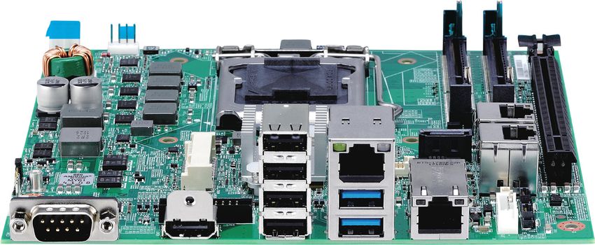
Contents

Contents

Preface                                                                                                             Chapter 2: Jumpers and Connectors
Copyright .............................................................................................. iv         Before You Begin.....................................................................................5
Disclaimer............................................................................................... iv        Precautions .............................................................................................5
Acknowledgements................................................................................ iv                 Jumper Settings.......................................................................................6
Regulatory Compliance Statements......................................................... iv                        Locations of the Jumpers and Connectors................................................7
Declaration of Conformity....................................................................... iv                 Jumpers...................................................................................................8
RoHS Compliance.................................................................................... v                 AT/ATX Power Type Selection................................................................8
Warranty and RMA................................................................................. vi                  RTC Clear ............................................................................................8
Safety Information.................................................................................viii             Connector Pin Definitions........................................................................9
Installation Recommendations................................................................viii                      External I/O Interfaces...........................................................................9
Safety Precautions................................................................................... ix                 COM Port.........................................................................................9
Technical Support and Assistance............................................................. x                          HDMI................................................................................................9
Conventions Used in this Manual............................................................. x                           LAN and USB 3.0 Ports....................................................................10
Global Service Contact Information......................................................... xi                           USB 2.0 Ports..................................................................................11
Package Contents...................................................................................xii                   LAN2 Port (PoE function requires optional PSE module)...................11
Ordering Information.............................................................................xiii                 Internal Connectors............................................................................12
                                                                                                                         DC-in Connector.............................................................................12
Chapter 1: Product Introduction                                                                                          Power Connector............................................................................12
Overview.................................................................................................1               Reset Connector.............................................................................13
Key Features............................................................................................1                BIOS Programming (for debugging only).........................................13
Hardware Specifications...........................................................................2                      PoE Connector................................................................................14
Knowing Your RCB 100...........................................................................3                         Internal LAN3 Port..........................................................................14
  Top View..............................................................................................3                Internal LAN4 Port..........................................................................15
  I/O Interfaces........................................................................................4                Internal USB 2.0 Connector.............................................................15
                                                                                                                         Internal USB 2.0 Connector.............................................................16
                                                                                                                         SATA Connector..............................................................................16

Copyright © 2020 NexCOBOT Co., Ltd. All Rights Reserved.                                                       ii                                                                                                RCB 100 User Manual
Contents

    SATA Power Connector...................................................................17
    RS232/RS422/RS485 Serial Port Box Header....................................17
    RTC Battery Connector....................................................................18
    System Fan Connector....................................................................18
    CPU Fan Connector.........................................................................19
    VGA Connector..............................................................................19
    GPIO Connector..............................................................................20
    Mini-PCIe Connector.......................................................................21
    PCIe x16 Slot...................................................................................22
Block Diagram .................................................................................24

Chapter 3: BIOS Setup
About BIOS Setup..................................................................................25
When to Configure the BIOS..................................................................25
Default Configuration............................................................................26
Entering Setup.......................................................................................26
Legends.................................................................................................26
BIOS Setup Utility...................................................................................28
  Main..................................................................................................28
  Advanced...........................................................................................29
  Chipset...............................................................................................35
  Security..............................................................................................38
  Boot...................................................................................................39
  Save & Exit.........................................................................................40

Copyright © 2020 NexCOBOT Co., Ltd. All Rights Reserved.                                                      iii   RCB 100 User Manual
Preface

Preface

Copyright                                                                                Regulatory Compliance Statements
This publication, including all photographs, illustrations and software, is              This section provides the FCC compliance statement for Class A devices and
protected under international copyright laws, with all rights reserved. No               describes how to keep the system CE compliant.
part of this manual may be reproduced, copied, translated or transmitted in
any form or by any means without the prior written consent from Nexcobot
Co., Ltd.
                                                                                         Declaration of Conformity
                                                                                         FCC
Disclaimer                                                                               This equipment has been tested and verified to comply with the limits for
                                                                                         a Class A digital device, pursuant to Part 15 of FCC Rules. These limits are
The information in this document is subject to change without prior notice               designed to provide reasonable protection against harmful interference when
and does not represent commitment from Nexcobot Co., Ltd. However, users                 the equipment is operated in a commercial environment. This equipment
may update their knowledge of any product in use by constantly checking its              generates, uses, and can radiate radio frequency energy and, if not installed
manual posted on our website: http://www.nexcobot.com. NexCOBOT shall                    and used in accordance with the instructions, may cause harmful interference
not be liable for direct, indirect, special, incidental, or consequential damages        to radio communications. Operation of this equipment in a residential area
arising out of the use of any product, nor for any infringements upon the rights         (domestic environment) is likely to cause harmful interference, in which
of third parties, which may result from such use. Any implied warranties of              case the user will be required to correct the interference (take adequate
merchantability or fitness for any particular purpose is also disclaimed.                measures) at their own expense.

Acknowledgements                                                                         CE
                                                                                         The product(s) described in this manual complies with all applicable
RCB 100 is a trademark of Nexcobot Co., Ltd. All other product names                     European Union (CE) directives if it has a CE marking. For computer systems
mentioned herein are registered trademarks of their respective owners.                   to remain CE compliant, only CE-compliant parts may be used. Maintaining
                                                                                         CE compliance also requires proper cable and cabling techniques.

Copyright © 2020 NexCOBOT Co., Ltd. All Rights Reserved.                            iv                                                                 RCB 100 User Manual
Preface
RoHS Compliance
NexCOBOT RoHS Environmental Policy and How to recognize NexCOBOT RoHS Products?
Status Update For existing products where there are non-RoHS and RoHS versions, the
NexCOBOT is a global citizen for building the digital suffix “(LF)” will be added to the compliant product name.
infrastructure. We are committed to providing green
products and services, which are compliant with All new product models launched after January 2013 will be RoHS compliant.
European Union RoHS (Restriction on Use of Hazardous Substance in They will use the usual NexCOBOT naming convention.
Electronic Equipment) directive 2011/65/EU, to be your trusted green
partner and to protect our environment.
RoHS restricts the use of Lead (Pb) < 0.1% or 1,000ppm, Mercury (Hg)
< 0.1% or 1,000ppm, Cadmium (Cd) < 0.01% or 100ppm, Hexavalent
Chromium (Cr6+) < 0.1% or 1,000ppm, Polybrominated biphenyls (PBB) <
0.1% or 1,000ppm, and Polybrominated diphenyl Ethers (PBDE) < 0.1% or
1,000ppm.
In order to meet the RoHS compliant directives, NexCOBOT has established an
engineering and manufacturing task force in to implement the introduction
of green products. The task force will ensure that we follow the standard
NexCOBOT development procedure and that all the new RoHS components
and new manufacturing processes maintain the highest industry quality
levels for which NexCOBOT are renowned.
The model selection criteria will be based on market demand. Vendors and
suppliers will ensure that all designed components will be RoHS compliant.
Copyright © 2020 NexCOBOT Co., Ltd. All Rights Reserved. v RCB 100 User ManualPreface
Warranty and RMA
NexCOBOT Warranty Period Repair Service Charges for Out-of-Warranty Products
NexCOBOT manufactures products that are new or equivalent to new in NexCOBOT will charge for out-of-warranty products in two categories, one
accordance with industry standard. NexCOBOT warrants that products will is basic diagnostic fee and another is component (product) fee.
be free from defect in material and workmanship for 2 years, beginning on
the date of invoice by NexCOBOT. System Level
▪▪ Component fee: NexCOBOT will only charge for main components such
NexCOBOT Return Merchandise Authorization (RMA) as SMD chip, BGA chip, etc. Passive components will be repaired for free,
▪▪ Customers shall enclose the “NexCOBOT RMA Service Form” with the ex: resistor, capacitor.
returned packages.
▪▪ Items will be replaced with NexCOBOT products if the original one cannot
▪▪ Customers must collect all the information about the problems be repaired. Ex: motherboard, power supply, etc.
encountered and note anything abnormal or, print out any on-screen
messages, and describe the problems on the “NexCOBOT RMA Service ▪▪ Replace with 3rd party products if needed.
Form” for the RMA number apply process.
▪▪ If RMA goods can not be repaired, NexCOBOT will return it to the
▪▪ Customers can send back the faulty products with or without accessories customer without any charge.
(manuals, cable, etc.) and any components from the card, such as CPU and
RAM. If the components were suspected as part of the problems, please Board Level
note clearly which components are included. Otherwise, NexCOBOT is ▪▪ Component fee: NexCOBOT will only charge for main components, such
not responsible for the devices/parts. as SMD chip, BGA chip, etc. Passive components will be repaired for free,
ex: resistors, capacitors.
▪▪ Customers are responsible for the safe packaging of defective products,
making sure it is durable enough to be resistant against further damage ▪▪ If RMA goods can not be repaired, NexCOBOT will return it to the
and deterioration during transportation. In case of damages occurred customer without any charge.
during transportation, the repair is treated as “Out of Warranty.”
▪▪ Any products returned by NexCOBOT to other locations besides the
customers’ site will bear an extra charge and will be billed to the customer.
Copyright © 2020 NexCOBOT Co., Ltd. All Rights Reserved. vi RCB 100 User ManualPreface Warnings Read and adhere to all warnings, cautions, and notices in this guide and the documentation supplied with the chassis, power supply, and accessory modules. If the instructions for the chassis and power supply are inconsistent with these instructions or the instructions for accessory modules, contact the supplier to find out how you can ensure that your computer meets safety and regulatory requirements. Cautions Electrostatic discharge (ESD) can damage system components. Do the described procedures only at an ESD workstation. If no such station is available, you can provide some ESD protection by wearing an antistatic wrist strap and attaching it to a metal part of the computer chassis. Copyright © 2020 NexCOBOT Co., Ltd. All Rights Reserved. vii RCB 100 User Manual
Preface

Safety Information                                                                     Installation Recommendations
Before installing and using the device, note the following precautions:                Ensure you have a stable, clean working environment. Dust and dirt can get
                                                                                       into components and cause a malfunction. Use containers to keep small
▪▪ Read all instructions carefully.                                                    components separated.

▪▪ Do not place the unit on an unstable surface, cart, or stand.                       Adequate lighting and proper tools can prevent you from accidentally
                                                                                       damaging the internal components. Most of the procedures that follow
▪▪ Follow all warnings and cautions in this manual.                                    require only a few simple tools, including the following:
▪▪ When replacing parts, ensure that your service technician uses parts
                                                                                       ▪▪ A Philips screwdriver
   specified by the manufacturer.
                                                                                       ▪▪ A flat-tipped screwdriver
▪▪ Avoid using the system near water, in direct sunlight, or near a heating
   device.                                                                             ▪▪ A grounding strap
▪▪ The load of the system unit does not solely rely for support from the               ▪▪ An anti-static pad
   rackmounts located on the sides. Firm support from the bottom is highly
   necessary in order to provide balance stability.                                    Using your fingers can disconnect most of the connections. It is recommended
                                                                                       that you do not use needle-nose pliers to disconnect connections as these
▪▪ The computer is provided with a battery-powered real-time clock circuit.            can damage the soft metal or plastic parts of the connectors.
   There is a danger of explosion if battery is incorrectly replaced. Replace
   only with the same or equivalent type recommended by the manufacturer.
   Discard used batteries according to the manufacturer’s instructions.

Copyright © 2020 NexCOBOT Co., Ltd. All Rights Reserved.                        viii                                                                RCB 100 User Manual
Preface
Safety Precautions 12. All cautions and warnings on the board should be noted.
1. Read these safety instructions carefully. 13. Use the correct mounting screws and do not over tighten the screws.
2. Keep this User Manual for later reference. 14. Keep the original packaging and the anti-static bag; in case the board
has to be returned for repair or replacement.
3. Disconnect the equipment from any AC outlet before cleaning or installing
a component inside the chassis. Use a damp cloth. Do not use liquid or
spray detergents for cleaning.
4. To prevent electrostatic build-up, leave the board in its anti-static bag
until you are ready to install it.
5. For plug-in equipment, the power outlet socket must be located near the
equipment and must be easily accessible.
6. Keep the board away from humidity.
7. Put the board on a stable surface. Dropping it or letting it fall may cause
damage.
8. Wear anti-static wrist strap.
9. Do all preparation work on a static-free surface.
10. Make sure the voltage of the power source is correct before
connecting the equipment to the power outlet.
11. Hold the board only by its edges. Be careful not to touch any of the
components, contacts or connections.
Copyright © 2020 NexCOBOT Co., Ltd. All Rights Reserved. ix RCB 100 User ManualPreface
Technical Support and Assistance Conventions Used in this Manual
1. For the most updated information of NexCOBOT products, visit
NexCOBOT’s website at www.nexcobot.com. Warning:
Information about certain situations, which if not observed,
2. For technical issues that require contacting our technical support team or can cause personal injury. This will prevent injury to yourself
sales representative, please have the following information ready before when performing a task.
calling:
– Product name and serial number
CAUTION!
Caution:
– Detailed information of the peripheral devices
Information to avoid damaging components or losing data.
– Detailed information of the installed software (operating system,
version, application software, etc.)
– A complete description of the problem
– The exact wordings of the error messages Note:
Provides additional information to complete a task easily.
Warning!
1. Handling the unit: carry the unit with both hands and handle it with care.
2. Maintenance: to keep the unit clean, use only approved cleaning products
or clean with a dry cloth.
Copyright © 2020 NexCOBOT Co., Ltd. All Rights Reserved. x RCB 100 User ManualPreface Global Service Contact Information Asia America Taiwan China USA NexCOBOT Taiwan NexCOBOT China NexCOBOT USA 13F, No.916, Chung-Cheng Rd., Room 501, Building 1, Haichuang Building, 2883 Bayview Drive, ZhongHe District, No.7 Qingyi Rd., Guicheng Street, Fremont CA 94538, USA New Taipei City, 23586, Taiwan, R.O.C. Nanhai District, Foshan City, Tel: +1-510-362-0800 Tel: +886-2-8226-7796 Guangdong Province, 528314, China Email: sales@nexcobot.com Fax: +886-2-8226-7792 Tel: +86-757-8625-7118 www.nexcobot.com.cn Email: sales@nexcobot.com Email: sales@nexcobot.com www.nexcobot.com.tw www.nexcobot.com.cn Copyright © 2020 NexCOBOT Co., Ltd. All Rights Reserved. xi RCB 100 User Manual
Preface

Package Contents
Before continuing, verify that the RCB 100 package that you received is
complete. Your package should have all the items listed in the following
table.

 Item      Name                                                          Qty
   1       RCB 100 Mainboard                                              1
   2       Driver CD                                                      1
   3       Quick Guide                                                    1

Optional Accessories
 Item Part Number                       Name                             Description
   1  10J200RCB04X0                     NISKPoE Kit for RCB 100 (A001)   PoE PSE Module

Copyright © 2020 NexCOBOT Co., Ltd. All Rights Reserved.                        xii       RCB 100 User Manual
Preface

Ordering Information
The following below provides ordering information for RCB 100.

RCB 100 (P/N: 10J200RCB00X0)
Mini-ITX board, 6th generation Intel® Core™ i7/i5/i3 and Intel® Celeron®
processor support

NISKPoE Kit (P/N: 10J200RCB04X0)
PoE PSE Module

Copyright © 2020 NexCOBOT Co., Ltd. All Rights Reserved.                   xiii   RCB 100 User Manual
Chapter 1: Product Introduction

Chapter 1: Product Introduction

Overview                                                       Key Features
                                                               ▪▪ Mini-ITX form factor

                                                               ▪▪ 6th generation Intel® Core™ i7/i5/i3 and Intel® Celeron® processors

                                                               ▪▪ Internal USB for software license dongle

                                                               ▪▪ Optional digital isolated I/O

                                                               ▪▪ PoE for machine vision application

                                                               ▪▪ Internal VGA for teach pendant

Copyright © 2020 NexCOBOT Co., Ltd. All Rights Reserved.   1                                                                RCB 100 User Manual
Chapter 1: Product Introduction
Hardware Specifications
CPU Support Edge I/O Interface
▪▪ Socket LGA1151, 6th generation Intel Core™ i7/i5/i3 processors and
®
▪▪ 1 x RS232/422/485 with auto flow control (default RI)
Intel® Celeron® processors, 14nm process ▪▪ 2 x USB 3.0, 4 x USB 2.0
▪▪ 2 x I211AT GbE LAN (one port can be used as a PoE port, IEEE 802.3af
Main Memory compliant; requires optional PSE board)
▪▪ Dual DDR4/SO-DIMMs, up to 32GB
Audio
Chipset ▪▪ Not supported
▪▪ Intel H110 PCH
®
Power Input
Onboard Interface ▪▪ Support AT/ATX mode
▪▪ 2 x I210-AT GbE LAN ▪▪ ATX 4-pin connector for 24V ± 10%
▪▪ 2 x USB 2.0
▪▪ 1 x VGA (1920 x 1200 @ 60Hz) Form Factor
▪▪ 1 x RS232/422/485 with auto flow control ▪▪ Dimensions: Mini-ITX (6.7-in x 6.7-in)
▪▪ 12in (NPN/PNP type), 4out (NPN type); requires optional board
Environment
Display ▪▪ Operating temperatures: 0°C to 60°C with CPU fan and system fan
▪▪ 1 x HDMI (4096 x 2160 @ 24Hz, 24 bpp) ▪▪ Storage temperature: -20°C to 80°C
▪▪ Relative humidity: 90%
Expansion
▪▪ 1 x PCIe x16 Gen3 Certifications
▪▪ 1 x Mini-PCIe ▪▪ CE
▪▪ 1 x SATA ▪▪ FCC Class A
▪▪ EN61000-6-4 / EN61000-6-2
Copyright © 2020 NexCOBOT Co., Ltd. All Rights Reserved. 2 RCB 100 User ManualChapter 1: Product Introduction
Knowing Your RCB 100
Top View
DC Input CPU FAN DIMM1 DIMM2
PCIe x16
SATA
RTC Clear
SATA Power
Mini-PCIe
LAN4
VGA
AT/ATX Select
Power LAN3
Reset
RTC Battery
System Fan USB2
GPIO
USB1
COM
PoE Connector
Copyright © 2020 NexCOBOT Co., Ltd. All Rights Reserved. 3 RCB 100 User ManualChapter 1: Product Introduction
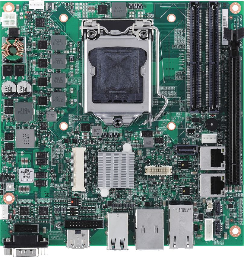
I/O Interfaces
COM HDMI USB 2.0 LAN LAN
USB 3.0
Copyright © 2020 NexCOBOT Co., Ltd. All Rights Reserved. 4 RCB 100 User ManualChapter 2: Jumpers and Connectors
Chapter 2: Jumpers and Connectors
This chapter describes how to set the jumpers and connectors on the dry environments. A grounding strap is warranted whenever danger of
RCB 100 motherboard. static electricity exists.
Before You Begin Precautions
▪▪ Ensure you have a stable, clean working environment. Dust and dirt can Computer components and electronic circuit boards can be damaged by
get into components and cause a malfunction. Use containers to keep discharges of static electricity. Working on computers that are still connected
small components separated. to a power supply can be extremely dangerous.
▪▪ Adequate lighting and proper tools can prevent you from accidentally
Follow the guidelines below to avoid damage to your computer or yourself:
damaging the internal components. Most of the procedures that follow
▪▪ Always disconnect the unit from the power outlet whenever you are
require only a few simple tools, including the following:
working inside the case.
– A Philips screwdriver
– A flat-tipped screwdriver ▪▪ If possible, wear a grounded wrist strap when you are working inside the
– A set of jewelers screwdrivers computer case. Alternatively, discharge any static electricity by touching
– A grounding strap the bare metal chassis of the unit case, or the bare metal body of any
– An anti-static pad other grounded appliance.
▪▪ Using your fingers can disconnect most of the connections. It is
recommended that you do not use needle-nosed pliers to disconnect ▪▪ Hold electronic circuit boards by the edges only. Do not touch the
connections as these can damage the soft metal or plastic parts of the components on the board unless it is necessary to do so. Don’t flex or
connectors. stress the circuit board.
▪▪ Before working on internal components, make sure that the power is off. ▪▪ Leave all components inside the static-proof packaging that they shipped
Ground yourself before touching any internal components, by touching with until they are ready for installation.
a metal object. Static electricity can damage many of the electronic
components. Humid environments tend to have less static electricity than ▪▪ Use correct screws and do not over tighten screws.
Copyright © 2020 NexCOBOT Co., Ltd. All Rights Reserved. 5 RCB 100 User ManualChapter 2: Jumpers and Connectors
Jumper Settings
A jumper is the simplest kind of electric switch. It consists of two metal
pins and a cap. When setting the jumpers, ensure that the jumper caps are
placed on the correct pins. When the jumper cap is placed on both pins, the
jumper is short. If you remove the jumper cap, or place the jumper cap on
just one pin, the jumper is open.
Refer to the illustrations below for examples of what the 2-pin and 3-pin
jumpers look like when they are short (on) and open (off).
Two-Pin Jumpers: Open (Left) and Short (Right)
Three-Pin Jumpers: Pins 1 and 2 are Short
3 3
2 2
1 1
Copyright © 2020 NexCOBOT Co., Ltd. All Rights Reserved. 6 RCB 100 User ManualChapter 2: Jumpers and Connectors
Locations of the Jumpers and Connectors
The figure below shows the location of the jumpers and connectors.
1
JDC1
4
DIMM1
1 1
DIMM2
2 2
JFAN2
+
1
3 CPU1
2
4
36 38 40
31 33 35 37 39
28303234
A82
A81
B82
B81
29
27 143
145 144 143 144
25 146 145 146
23
24
2 4 6 8 10 12 14 16 18 20 2226
21
19
17
15
13
11
9
7
5
3
1
AW
AN
AFAG
AU
AA
AC
ATAR
AE
AL
W
AJ
G
U
PN
A
C
R
AM
E
L
J
AD
AH
AB
AK
AP
AV
AY
M
D
H
V
B
K
Y
T
F
259
259
260
260
JPCIE1
JRTC1
1 3
JSP1
JSATA1 9 10
4 1
13 14
51
52
1 7
VGA1
LAN4
11 12
JMINI1
1 19
2
1
17
LAN3
1618
JATX1
1 10
9
13 14
15
2 20
B2
A2
3
B1
A1
JP1
1
2 1
2
JP2
11 12
1
LAN2
2 2
1
JFW1 CON1 L4 L3 L1 1
1
1
JFAN1
1 2
CN2 29 30 31 32
12
6
7
1 2 USB2
JBAT1
4
CN4 13 16 28 20
5 6
COM2
4 27 19
9 12 14 13
19 1 18 14 16 15 1 1
USB1
20 2 5 8
9 1
10 2 19 1 4
1 4
17 2 1 4
18 4
1 5 5
JP3
6 9
COM1 HDMI1 USB 2.0 x 4 USB 3.0 x 2
RJ45 Port
RJ45 Port
*PoE function
(need optional PSE module)
Copyright © 2020 NexCOBOT Co., Ltd. All Rights Reserved. 7 RCB 100 User ManualChapter 2: Jumpers and Connectors
Jumpers
AT/ATX Power Type Selection RTC Clear
Connector type: 1x3 3-pin header, 2.0mm pitch Connector type: 1x3 3-pin header, 2.54mm pitch
Connector location: JATX1 Connector location: JRTC1
1 3 1 3
Pin Function Pin Definition
1-2 On ATX Mode 1 VCCRTC
2-3 On AT Mode 2 VCCRTC_R
2-3 On: default 3 GND
1-2 On: default
Pin Definition
1 Manual (ATX MODE)
2 PWRBT In
3 AUTO (AT MODE)
Copyright © 2020 NexCOBOT Co., Ltd. All Rights Reserved. 8 RCB 100 User ManualChapter 2: Jumpers and Connectors
Connector Pin Definitions
External I/O Interfaces
COM Port HDMI
Connector type: DB-9 port, 9-pin D-Sub Connector type: HDMI port
Connector location: COM1 Connector location: HDMI1
1 5 19 1
6 9 18 2
Pin Definition Pin Definition Pin Definition Pin Definition
1 COM_DCD#1 2 COM_RXD#1 1 HDMI_D2+_C 2 GND
3 COM_TXD#1 4 COM_DTR#1 3 HDMI_D2-_C 4 HDMI_D1+_C
5 COM_GND 6 COM_DSR#1 5 GND 6 HDMI_D1-_C
7 COM_RTS#1 8 COM_CTS#1 7 HDMI_D0+_C 8 GND
9 COM_RI#1 9 HDMI_D0-_C 10 HDMI_CK+_C
11 GND 12 HDMI_CK-_C
13 NC 14 NC
15 HDMI_SCL_C 16 HDMI_SDA_C
17 GND 18 VCC5
19 HDMI_HPD
Copyright © 2020 NexCOBOT Co., Ltd. All Rights Reserved. 9 RCB 100 User ManualChapter 2: Jumpers and Connectors
LAN and USB 3.0 Ports
Connector type: RJ45 port with LEDs
Dual USB 3.0 ports, Type A
Connector location: CON1
Act Status
ACT LINK
Flashing Yellow Data activity
Off No activity
27 20
10 18 14 13 Link Status
Steady Green 1G network link
9 5
1 4 Steady Orange 100Mbps network link
Off 10Mbps or no link
Pin Definition Pin Definition Pin Definition Pin Definition
1 P5V_USB_P01 2 USB2N1_C 17 USB3TN2_C 18 USB3TP2_C
3 USB2P1_C 4 GND 19 LAN1_VCC 20 LAN1_MDI0P
5 USB3RN1_C 6 USB3RP1_C 21 LAN1_MDI0N 22 LAN1_MDI1P
7 GND 8 USB3TN1_C 23 LAN1_MDI1N 24 LAN1_MDI2P
9 USB3TP1_C 10 P5V_USB_P01 25 LAN1_MDI2N 26 LAN1_MDI3P
11 USB2N2_C 12 USB2P2_C 27 LAN1_MDI3N 28 GND
13 GND 14 USB3RN2_C 29 LAN1_ACT_P 30 ACT_LED#
15 USB3RP2_C 16 GND 31 LAN1_LINK100#_P 32 LAN1_LINK1G#
Copyright © 2020 NexCOBOT Co., Ltd. All Rights Reserved. 10 RCB 100 User ManualChapter 2: Jumpers and Connectors
USB 2.0 Ports LAN2 Port (PoE function requires optional PSE module)
Connector type: Four USB 2.0 ports, Type A Connector type: RJ45 port with LEDs
Connector location: CN2 Connector location: LAN2
1 4
Act Status
Flashing Yellow Data activity
ACT LINK Off No activity
5 8
9 12 8 1 Link Status
Steady Green 1G network link
13 16 Steady Orange 100Mbps network link
Off 10Mbps or no link
Pin Definition Pin Definition Pin Definition Pin Definition
1 P5V_USB_P56 2 USB2N5_C 1 NC 2 LAN2_MDI2N
3 USB2P5_C 4 GND 3 LAN2_MDI2P 4 LAN2_MDI1P
5 P5V_USB_P56 6 USB2N6_C 5 LAN2_MDI1N 6 NC
7 USB2P6_C 8 GND 7 NC 8 LAN2_MDI3P
9 P5V_USB_P78 10 USB2N7_C 9 LAN2_MDI3N 10 LAN2_MDI0N
11 USB2P7_C 12 GND 11 LAN2_MDI0P 12 NC
13 P5V_USB_P78 14 USB2N8_C 13 VPORT_POS_ALT_A 14 VPORT_NEG_ALT_A
15 USB2P8_C 16 GND 15 NC 16 NC
L1 LAN2_LINK1G# L2 LAN2_LINK100#
L3 LAN2_LED_ACT# L4 LAN2_ACT_P
Copyright © 2020 NexCOBOT Co., Ltd. All Rights Reserved. 11 RCB 100 User ManualChapter 2: Jumpers and Connectors
Internal Connectors
DC-in Connector Power Connector
Connector type: 2x2 Aux power connector Connector type: 1x2 2-pin header, 2.0mm pitch
Connector location: JDC1 Connector location: JP1
1 2
1 2
3 4
Pin Definition Pin Definition
1 GND 1 PWRBTN#_C
2 GND 2 GND
3 +24V
4 +24V
Copyright © 2020 NexCOBOT Co., Ltd. All Rights Reserved. 12 RCB 100 User ManualChapter 2: Jumpers and Connectors
Reset Connector BIOS Programming (for debugging only)
Connector type: 1x2 2-pin header, 2.0mm pitch Connector type: 2x3 6-pin header, 2.0mm pitch
Connector location: JP2 Connector location: JFW1
2 6
1 2
1 5
Pin Definition Pin Definition Pin Definition
1 RESET 1 3.3V 2 GND
2 GND 3 SPI_CS# 4 SPI_CK
5 SPI_SO 6 SPI_SI
Copyright © 2020 NexCOBOT Co., Ltd. All Rights Reserved. 13 RCB 100 User ManualChapter 2: Jumpers and Connectors
PoE Connector Internal LAN3 Port
Connector type: 1x5 5-pin header, 2.5mm pitch Connector type: RJ45 port with LEDs
Connector location: JP3 Connector location: LAN3
Act Status
Flashing Yellow Data activity
ACT LINK Off No activity
1 5 8 1 Link Status
Steady Green 1G network link
Steady Orange 100Mbps network link
Off 10Mbps or no link
Pin Definition Pin Definition Pin Definition Pin Definition
1 VIN_M 2 GND 1 LAN3_MDI0P 2 LAN3_MDI0N
3 NC 4 VPORT_POS_ALT_A 3 LAN3_MDI1P 4 LAN3_MDI1N
5 VPORT_NEG_ALT_A 5 LAN3_VCC 6 LAN3TCTG
7 LAN3_MDI2P 8 LAN3_MDI2N
9 LAN3_MDI3P 10 LAN3_MDI3N
11 LAN3_LINK1G#_LED 12 LAN3_LINK
13 LAN3_ACT#_LED 14 LAN3_ACTPW
Copyright © 2020 NexCOBOT Co., Ltd. All Rights Reserved. 14 RCB 100 User ManualChapter 2: Jumpers and Connectors
Internal LAN4 Port Internal USB 2.0 Connector
Connector type: RJ45 port with LEDs Connector type: 1x4 4-pin header, 1.25mm pitch
Connector location: LAN4 Connector location: USB1
Act Status
Flashing Yellow Data activity
ACT LINK Off No activity
1 4
8 1 Link Status
Steady Green 1G network link
Steady Orange 100Mbps network link
Off 10Mbps or no link
Pin Definition Pin Definition Pin Definition Pin Definition
1 LAN4_MDI0P 2 LAN4_MDI0N 1 P5V_USB_P9_P4 2 USB2N9_C
3 LAN4_MDI1P 4 LAN4_MDI1N 3 USB2P9_C 4 GND
5 LAN4_VCC 6 LAN4TCTG
7 LAN4_MDI2P 8 LAN4_MDI2N
9 LAN4_MDI3P 10 LAN4_MDI3N
11 LAN4_LINK1G# 12 LAN4_LINK100#_P
13 LAN4_LED_ACT# 14 LAN4_ACT_P
Copyright © 2020 NexCOBOT Co., Ltd. All Rights Reserved. 15 RCB 100 User ManualChapter 2: Jumpers and Connectors
Internal USB 2.0 Connector SATA Connector
Connector type: 1x4 4-pin header, 1.25mm pitch Connector type: Standard Serial ATA 7P (1.27mm, SATA-M-180)
Connector location: USB2 Connector location: JSATA1
1 4
1 7
Pin Definition Pin Definition Pin Definition Pin Definition
1 P5V_USB_P9_P4 2 USB2N4_C 1 GND 2 SATA_TXP1_C
3 USB2P4_C 4 GND 3 SATA_TXN1_C 4 GND
5 SATA_RXN1_C 6 SATA_RXP1_C
7 GND
Copyright © 2020 NexCOBOT Co., Ltd. All Rights Reserved. 16 RCB 100 User ManualChapter 2: Jumpers and Connectors
SATA Power Connector RS232/RS422/RS485 Serial Port Box Header
Connector type: 1x4 4-pin header, 1.25mm pitch Connector type: 2x5 10-pin header, 2.0mm pitch
Connector location: JSP1 Connector location: COM2
2 10
10
1 4
1 9
Pin Definition Pin Definition Pin Definition Pin Definition
1 VCC12 2 GND 1 COM_DCD#2 2 COM_RXD#2
3 GND 4 VCC5 3 COM_TXD#2 4 COM_DTR#2
5 COM_GND 6 COM_DSR#2
7 COM_RTS#2 8 COM_CTS#2
9 COM_RI#2
Copyright © 2020 NexCOBOT Co., Ltd. All Rights Reserved. 17 RCB 100 User ManualChapter 2: Jumpers and Connectors
RTC Battery Connector System Fan Connector
Connector type: 1x2 JST, 2-pin header, 1.25mm pitch Connector type: 1x4 4-pin header, 2.54mm pitch
Connector location: JBAT1 Connector location: JFAN1
1 2 1 4
Pin Definition Pin Definition Pin Definition
1 BATT- 1 GND 2 FAN2_12V_C
2 BATT+ 3 FAN_TAC2_C 4 FAN_CTL2_C
Copyright © 2020 NexCOBOT Co., Ltd. All Rights Reserved. 18 RCB 100 User ManualChapter 2: Jumpers and Connectors
CPU Fan Connector VGA Connector
Connector type: 1x4 4-pin header, 2.54mm pitch Connector type: 2x10 20-pin header, 1.25mm pitch
Connector location: JFAN2 Connector location: VGA1
20 2
1 4
19 1
Pin Definition Pin Definition Pin Definition Pin Definition
1 GND 2 FAN1_12V_C 1 GND 2 RED_VGA
3 FAN_TAC1_C 4 FAN_CTL1_C 3 GND 4 GREEN_VGA
5 GND 6 BLUE_VGA
7 NC 8 GND
9 NC 10 VSYNC_VGA
11 GND 12 HSYNC_VGA
13 VGA_SCL_C 14 GND
15 VGA_SDA_C 16 GND
17 GND 18 NC
19 NC 20 VGA_+5V
Copyright © 2020 NexCOBOT Co., Ltd. All Rights Reserved. 19 RCB 100 User ManualChapter 2: Jumpers and Connectors
GPIO Connector
Connector type: 2x10 20-pin header, 2.0mm pitch
Connector location: CN4
2 20
1 19
Pin Definition Pin Definition
1 GPIO_I0 2 GPIO_I8
3 GPIO_I1 4 GPIO_I9
5 GPIO_I2 6 GPIO_I10
7 GPIO_I3 8 GPIO_I11
9 GPIO_I4 10 GPIO_O0
11 GPIO_I5 12 GPIO_O1
13 GPIO_I6 14 GPIO_O2
15 GPIO_I7 16 GPIO_O3
17 GPIO_GND 18 GPIO_GND
19 VCC5_GPIO 20 VCC5_GPIO
Copyright © 2020 NexCOBOT Co., Ltd. All Rights Reserved. 20 RCB 100 User ManualChapter 2: Jumpers and Connectors
Mini-PCIe Connector
Connector location: JMINI1
1 2
51 52
Pin Definition Pin Definition Pin Definition Pin Definition
1 WAKE0# 2 +V3.3_MINI2 27 GND 28 1V5_MINI2
3 NC 4 GND 29 GND 30 SMB_CLK
5 NC 6 +1V5_MINI2 31 PCIE_TN6_MINI_C 32 SMB_DAT
7 PCIE_CLKREQ6# 8 NC 33 PCIE_TP6_MINI_C 34 GND
9 GND 10 NC 35 GND 36 USB2N10_C
11 CLK_PCIE_MINI_N 12 NC 37 GND 38 USB2P10_C
13 CLK_PCIE_MINI_P 14 NC 39 3VSB_MINI2 40 GND
15 GND 16 NC 41 3VSB_MINI2 42 NC
17 NC 18 GND 43 GND 44 NC
19 NC 20 W_DISABLE# 45 CL_CLK_C 46 NC
21 GND 22 PCIE_RST# 47 CL_DAT_C 48 1V5_MINI2
23 PCIE_RN6_MINI_C 24 3VSB_MINI2 49 CL_RST#_C 50 GND
25 PCIE_RP6_MINI_C 26 GND 51 PCIE_mSATA_SEL 52 3VSB_MINI2
Copyright © 2020 NexCOBOT Co., Ltd. All Rights Reserved. 21 RCB 100 User ManualChapter 2: Jumpers and Connectors
PCIe x16 Slot
Connector location: JPCIE1
A1 A11 A12 A82
B1 B11 B12 B82
Pin Definition Pin Definition Pin Definition Pin Definition
A1 PCIE_PRSNT1 B1 12V A19 NC B19 PET1+
A2 12V B2 12V A20 GND B20 PET1-
A3 12V B3 12V A21 PER1+ B21 GND
A4 GND B4 GND A22 PER1- B22 GND
A5 TCK B5 SMB_CLK A23 GND B23 PET2+
A6 TDI B6 SMB_DATA A24 GND B24 PET2-
A7 NC B7 GND A25 PER2+ B25 GND
A8 TMS B8 3.3V A26 PER2- B26 GND
A9 3.3V B9 GND A27 GND B27 PET3+
A10 3.3V B10 3.3V standby A28 GND B28 PET3-
A11 RESET# B11 Wake# A29 PER3+ B29 GND
A12 GND B12 NC A30 PER3- B30 NC
A13 CLK+ B13 GND A31 GND B31 NC
A14 CLK- B14 PET0+ A32 NC B32 GND
A15 GND B15 PET0- A33 NC B33 PET4+
A16 PER0+ B16 GND A34 GND B34 PET4-
A17 PER0- B17 PCIECLKRQ8# A35 PER4+ B35 GND
A18 GND B18 GND A36 PER4- B36 GND
Copyright © 2020 NexCOBOT Co., Ltd. All Rights Reserved. 22 RCB 100 User ManualChapter 2: Jumpers and Connectors
Pin Definition Pin Definition Pin Definition Pin Definition
A37 GND B37 PET5+ A60 PER10+ B60 GND
A38 GND B38 PET5- A61 PER10- B61 GND
A39 PER5+ B39 GND A62 GND B62 PET11+
A40 PER5- B40 GND A63 GND B63 PET11-
A41 GND B41 PET6+ A64 PER11+ B64 GND
A42 GND B42 PET6- A65 PER11- B65 GND
A43 PER6+ B43 GND A66 GND B66 PET12+
A44 PER6- B44 GND A67 GND B67 PET12-
A45 GND B45 PET7+ A68 PER12+ B68 GND
A46 GND B46 PET7- A69 PER12- B69 GND
A47 PER7+ B47 GND A70 GND B70 PET13+
A48 PER7- B48 NC A71 GND B71 PET13-
A49 GND B49 GND A72 PER13+ B72 GND
A50 NC B50 PET8+ A73 PER13- B73 GND
A51 GND B51 PET8- A74 GND B74 PET14+
A52 PER8+ B52 GND A75 GND B75 PET14-
A53 PER8- B53 GND A76 PER14+ B76 GND
A54 GND B54 PET9+ A77 PER14- B77 GND
A55 GND B55 PET9- A78 GND B78 PET15+
A56 PER9+ B56 GND A79 GND B79 PET15-
A57 PER9- B57 GND A80 PER15+ B80 GND
A58 GND B58 PET10+ A81 PER15- B81 NC
A59 GND B59 PET10- A82 GND B82 NC
Copyright © 2020 NexCOBOT Co., Ltd. All Rights Reserved. 23 RCB 100 User ManualChapter 2: Jumpers and Connectors
Block Diagram
IMVP8 VCCIN Maximum support 16GB
DDR4 CH A
PCIEx 16 DDR4 1866/2133 MT/s SO-DIMM
SKYLAKE-S DDR4 CHA
DP B DP C DP DDP A/E PEG
SLOT1 PEG[0:15]Chapter 3: BIOS Setup
Chapter 3: BIOS Setup
This chapter describes how to use the BIOS setup program for RCB 100. The The settings made in the setup program affect how the computer performs.
BIOS screens provided in this chapter are for reference only and may change It is important, therefore, first to try to understand all the setup options, and
if the BIOS is updated in the future. second, to make settings appropriate for the way you use the computer.
To check for the latest updates and revisions, visit the NexCOBOT website at
www.nexcobot.com. When to Configure the BIOS
▪▪ This program should be executed under the following conditions:
About BIOS Setup ▪▪ When changing the system configuration
The BIOS (Basic Input and Output System) Setup program is a menu driven ▪▪ When a configuration error is detected by the system and you are
utility that enables you to make changes to the system configuration and prompted to make changes to the setup program
tailor your system to suit your individual work needs. It is a ROM-based
▪▪ When resetting the system clock
configuration utility that displays the system’s configuration status and
provides you with a tool to set system parameters. ▪▪ When redefining the communication ports to prevent any conflicts
▪▪ When making changes to the Power Management configuration
These parameters are stored in non-volatile battery-backed-up CMOS RAM that
▪▪ When changing the password or making other changes to the security
saves this information even when the power is turned off. When the system is
setup
turned back on, the system is configured with the values found in CMOS.
Normally, CMOS setup is needed when the system hardware is not consistent
With easy-to-use pull down menus, you can configure such items as: with the information contained in the CMOS RAM, whenever the CMOS
▪▪ Hard drives, diskette drives, and peripherals RAM has lost power, or the system features need to be changed.
▪▪ Video display type and display options
▪▪ Password protection from unauthorized use
▪▪ Power management features
Copyright © 2020 NexCOBOT Co., Ltd. All Rights Reserved. 25 RCB 100 User ManualChapter 3: BIOS Setup
Default Configuration Legends
Most of the configuration settings are either predefined according to Key Function
the Load Optimal Defaults settings which are stored in the BIOS or are
automatically detected and configured without requiring any actions. There Moves the highlight left or right to select a menu.
are a few settings that you may need to change depending on your system
configuration. Moves the highlight up or down between
sub-menus or fields.
Entering Setup Exits the BIOS Setup Utility.
When the system is powered on, the BIOS will enter the Power-On Self
Scrolls forward through the values or options of the
Test (POST) routines. These routines perform various diagnostic checks; if an
highlighted field.
error is encountered, the error will be reported in one of two different ways:
Scrolls backward through the values or options of
▪▪ If the error occurs before the display device is initialized, a series of beeps the highlighted field.
will be transmitted.
Selects a field.
▪▪ If the error occurs after the display device is initialized, the screen will
display the error message. Displays General Help.
Powering on the computer and immediately pressing allows you to Load previous values.
enter Setup.
Load optimized default values.
Press the key to enter Setup:
Saves and exits the Setup program.
Press to enter the highlighted sub-menu
Copyright © 2020 NexCOBOT Co., Ltd. All Rights Reserved. 26 RCB 100 User ManualChapter 3: BIOS Setup Scroll Bar When a scroll bar appears to the right of the setup screen, it indicates that there are more available fields not shown on the screen. Use the up and down arrow keys to scroll through all the available fields. Submenu When “” appears on the left of a particular field, it indicates that a submenu which contains additional options are available for that field. To display the submenu, move the highlight to that field and press . Copyright © 2020 NexCOBOT Co., Ltd. All Rights Reserved. 27 RCB 100 User Manual
Chapter 3: BIOS Setup
BIOS Setup Utility Main
Aptio Setup Utility - Copyright (C) 2018 American Megatrends, Inc.
Advanced Chipset Security Boot Save & Exit
Once you enter the AMI BIOS Setup Utility, the Main Menu will appear on Stepping R0/S0/N0 ▲ Set the Time. Use Tab to
the screen. The main menu allows you to select from several setup functions Number of Processors 4Core(s) / 4Thread(s) switch between Time elements.
Microcode Revision A6
and one exit. Use arrow keys to select among the items and press to GT Info GT2 (0x1912)
accept or enter the submenu. IGFX VBIOS Version 1028
Memory RC Version 2.0.0.6
Total Memory 8192 MB
Memory Frequency 2133 MHz
Main PCH Information
The Main menu is the first screen that you will see when you enter the BIOS Name SKL PCH-H
PCH SKU H110
Setup Utility. Stepping D1
52
Hsio Revision →←: Select Screen
TXT Capability of Platform/PCH Supported ↑↓: Select Item
Production Type Production Enter: Select
+/-: Change Opt.
Aptio Setup Utility - Copyright (C) 2018 American Megatrends, Inc. ME FW Version 11.6.10.1196 F1: General Help
ME Firmware SKU Consumer SKU F2: Previous Values
Main Advanced Chipset Security Boot Save & Exit F3: Optimized Defaults
System Language [English] F4: Save & Exit
ESC: Exit
BIOS Information ▲ Choose the system default
System Date [Tue 02/11/2020]
BIOS Vendor American Megatrends language
System Time [15:52:31]
Core Version 5.12 ▼
Compliancy UEFI 2.5; PI 1.4
Project Version Z100A010 x64
Version 2.18.1263. Copyright (C) 2018 American Megatrends, Inc.
Build Date and Time 09/10/2018 15:14:57
Access Level Administrator
Board Information
System Language
Board ID SKYBAY Selects the language of the system.
Processor Information
Name Skylake DT
Type Intel(R) Core(TM) System Date
i5-6500 CPU @ 3.20GHz →←: Select Screen The date format is , , , . Day displays a day,
Speed 3200 MHz ↑↓: Select Item
ID 0x506E3 Enter: Select from Monday to Sunday. Month displays the month, from January to
Stepping R0/S0/N0 +/-: Change Opt.
Number of Processors 4Core(s) / 4Thread(s) F1: General Help December. Date displays the date, from 1 to 31. Year displays the year, from
Microcode Revision A6 F2: Previous Values
GT Info GT2 (0x1912) F3: Optimized Defaults 1999 to 2099.
F4: Save & Exit
IGFX VBIOS Version 1028 ESC: Exit
Memory RC Version 2.0.0.6 System Time
Total Memory 8192 MB
▼ The time format is , , . The time is based on the
Version 2.18.1263. Copyright (C) 2018 American Megatrends, Inc.
24-hour military-time clock. For example, 1 p.m. is 13:00:00. Hour displays
hours from 00 to 23. Minute displays minutes from 00 to 59. Second displays
seconds from 00 to 59.
Copyright © 2020 NexCOBOT Co., Ltd. All Rights Reserved. 28 RCB 100 User ManualChapter 3: BIOS Setup
Advanced CPU Configuration
This section is used to configure the CPU.
The Advanced menu allows you to configure your system for basic operation.
Some entries are defaults required by the system board, while others, if Aptio Setup Utility - Copyright (C) 2018 American Megatrends, Inc.
Advanced
enabled, will improve the performance of your system or let you set some
features according to your preference. CPU Configuration When enabled, a VMM can
utilize the additional
hardware capabilities provided
Type Intel(R) Core(TM) by Vanderpool Technology.
i5-6500 CPU @ 3.20GHz
Setting incorrect field values may cause the system to ID 0x506E3
malfunction. Speed 3200 MHz
L1 Data Cache 32 KB x 4
L1 Instruction Cache 32 KB x 4
L2 Cache 256 KB x 4
Aptio Setup Utility - Copyright (C) 2018 American Megatrends, Inc. L3 Cache 6 MB
Main Advanced Chipset Security Boot Save & Exit L4 Cache N/A
VMX Supported
SMX/TXT Supported
CPU Configuration CPU Configuration Parameters. →←: Select Screen
↑↓: Select Item
Power & Performance Intel (VMX) Virtualization [Enabled] Enter: Select
IT8786 Super IO Configuration Technology +/-: Change Opt.
Hardware Monitor Active Processor Cores [All] F1: General Help
F2: Previous Values
CSM Configuration Hyper-Threading [Disabled] F3: Optimized Defaults
USB Configuration F4: Save & Exit
ESC: Exit
Version 2.18.1263. Copyright (C) 2018 American Megatrends, Inc.
→←: Select Screen
↑↓: Select Item
Enter: Select
Intel® (VMX) Virtualization Technology
+/-: Change Opt.
F1: General Help
Enables or disables Intel Virtualization technology.
F2: Previous Values
F3: Optimized Defaults
F4: Save & Exit Active Processors Cores
ESC: Exit
Select the number of cores to enable in each processor package.
Hyper-Threading
Version 2.18.1263. Copyright (C) 2018 American Megatrends, Inc.
Enables or disables hyper-threading technology.
Copyright © 2020 NexCOBOT Co., Ltd. All Rights Reserved. 29 RCB 100 User ManualChapter 3: BIOS Setup
Power & Performance CPU - Power Management Control
This section is used to configure the CPU power management features. Aptio Setup Utility - Copyright (C) 2019 American Megatrends, Inc.
Advanced
Aptio Setup Utility - Copyright (C) 2019 American Megatrends, Inc.
Advanced
CPU - Power Management Control Allows more than two frequency
ranges to be supported.
Power & Performance CPU - Power Management Intel(R) SpeedStep(tm) [Disabled]
Control Options
C states [Disabled]
CPU - Power Management Control
→←: Select Screen
↑↓: Select Item
Enter: Select
→←: Select Screen
+/-: Change Opt.
↑↓: Select Item
F1: General Help
Enter: Select
F2: Previous Values
+/-: Change Opt.
F3: Optimized Defaults
F1: General Help
F4: Save & Exit
F2: Previous Values
ESC: Exit
F3: Optimized Defaults
F4: Save & Exit
ESC: Exit
Version 2.18.1263. Copyright (C) 2019 American Megatrends, Inc.
Version 2.18.1263. Copyright (C) 2019 American Megatrends, Inc.
Intel® SpeedStepTM
CPU - Power Management Control Enables or disables Intel SpeedStep technology.
Enters the CPU - Power Management Control submenu.
C states
Enables or disables CPU C states support for power saving.
Copyright © 2020 NexCOBOT Co., Ltd. All Rights Reserved. 30 RCB 100 User ManualChapter 3: BIOS Setup
IT8786 Super IO Configuration Serial Port 1 Configuration
This section is used to configure the I/O functions supported by the onboard This section is used to configure serial port 1.
Super I/O chip.
Aptio Setup Utility - Copyright (C) 2018 American Megatrends, Inc.
Aptio Setup Utility - Copyright (C) 2018 American Megatrends, Inc. Advanced
Advanced
Serial Port 1 Configuration Enable or Disable Serial Port
(COM)
IT8786 Super IO Configuration Set Parameters of Serial Port
Serial Port [Enabled]
1 (COMA)
Device Settings IO=3F8h; IRQ=4;
Super IO Chip IT8786 Onboard Serial Port Mode [RS232]
Serial Port 1 Configuration Terminal resistor [Enabled]
Serial Port 2 Configuration
→←: Select Screen
↑↓: Select Item
→←: Select Screen Enter: Select
↑↓: Select Item +/-: Change Opt.
Enter: Select F1: General Help
+/-: Change Opt. F2: Previous Values
F1: General Help F3: Optimized Defaults
F2: Previous Values F4: Save & Exit
F3: Optimized Defaults ESC: Exit
F4: Save & Exit
ESC: Exit
Version 2.18.1263. Copyright (C) 2018 American Megatrends, Inc.
Version 2.18.1263. Copyright (C) 2018 American Megatrends, Inc.
Serial Port
Super IO Chip Enables or disables the serial port.
Displays the Super I/O chip used on the board.
Onboard Serial Port Mode
Select this to change the serial port mode to RS232, RS422, RS485 or RS485
AUTO.
Terminal resistor
Enables or disables the terminal resistor.
Copyright © 2020 NexCOBOT Co., Ltd. All Rights Reserved. 31 RCB 100 User ManualChapter 3: BIOS Setup
Serial Port 2 Configuration Hardware Monitor
This section is used to configure serial port 2. This section is used to monitor hardware status such as temperature, fan
speed and voltages.
Aptio Setup Utility - Copyright (C) 2018 American Megatrends, Inc.
Advanced Aptio Setup Utility - Copyright (C) 2018 American Megatrends, Inc.
Advanced
Serial Port 2 Configuration Enable or Disable Serial Port
(COM)
Pc Health Status
Serial Port [Enabled]
Device Settings IO=2F8h; IRQ=3;
FAN Setting [Enable Smart Fan]
Onboard Serial Port Mode [RS232]
Set Temp.-active S.F. [35 C/ 95 F]
Terminal resistor [Enabled]
Set Temp.-active full run [75 C/167 F]
Initial FAN speed (S.F.) [32 %]
System Temperature : +36 ºc
CPU Temperature : +47 ºc
CPU FAN SPEED : 866 RPM
SYSTEM FAN SPEED : N/A
→←: Select Screen CPU:Vcore : +1.128 V
↑↓: Select Item +3V : +3.324 V
Enter: Select →←: Select Screen
+/-: Change Opt.
+12V : +12.240 V ↑↓: Select Item
F1: General Help +5V : +5.040 V Enter: Select
F2: Previous Values +/-: Change Opt.
F3: Optimized Defaults F1: General Help
F4: Save & Exit F2: Previous Values
ESC: Exit F3: Optimized Defaults
F4: Save & Exit
ESC: Exit
Version 2.18.1263. Copyright (C) 2018 American Megatrends, Inc.
Version 2.20.1271. Copyright (C) 2018 American Megatrends, Inc.
Serial Port
Enables or disables the serial port. FAN Setting
Configures the operating mode of the fan.
Onboard Serial Port Mode
Select this to change the serial port mode to RS232, RS422, RS485 or RS485 Set Temp.-active S.F.
AUTO. Configures the temperature threshold to activate smart fan.
Terminal resistor Set Temp.-active full run
Enables or disables the terminal resistor. Configures the temperature threshold to activate the fan in full speed.
Copyright © 2020 NexCOBOT Co., Ltd. All Rights Reserved. 32 RCB 100 User ManualChapter 3: BIOS Setup
Initial FAN Speed (S.F.) CSM Configuration
Configures the starting fan speed of smart fan. This section is used to configure the compatibility support module features.
System Temperature Aptio Setup Utility - Copyright (C) 2019 American Megatrends, Inc.
Advanced
Detects and displays the current system temperature.
Compatibility Support Module Configuration Enable/Disable CSM Support.
CPU Temperature
CSM Support [Enabled]
Detects and displays the current CPU temperature.
CSM16 Module Version 07.80
CPU FAN SPEED GateA20 Active [Upon Request]
Detects and displays the current CPU fan speed. Option ROM Messages [Force BIOS]
INT19 Trap Response [Immediate]
SYSTEM FAN SPEED Boot option filter [Legacy only]
Detects and displays the current system fan speed. Option ROM execution
→←: Select Screen
↑↓: Select Item
Storage [Legacy] Enter: Select
CPU:Vcore Video [Legacy] +/-: Change Opt.
F1: General Help
Other PCI devices [Legacy]
Detects and displays the Vcore voltage. F2: Previous Values
F3: Optimized Defaults
F4: Save & Exit
ESC: Exit
+3V
Detects and displays the 3.3V voltage.
Version 2.18.1263. Copyright (C) 2019 American Megatrends, Inc.
+12V
Detects and displays the 12V voltage. CSM Support
This field is used to enable or disable CSM support, if Auto option is selected,
+5V based on OS, CSM will be enabled or disabled automatically.
Detects and displays the 5V voltage.
GateA20 Active
Upon Request GA20 can be disabled using BIOS services.
Always Do not allow disabling GA20; this option is useful when
any RT code is executed above 1MB.
Copyright © 2020 NexCOBOT Co., Ltd. All Rights Reserved. 33 RCB 100 User ManualChapter 3: BIOS Setup
Option ROM Messages USB Configuration
This field is used to set display mode for Option ROM. The options are Force This section is used to configure the USB.
BIOS and Keep Current.
Aptio Setup Utility - Copyright (C) 2018 American Megatrends, Inc.
INT19 Trap Response Advanced
Allows Option ROMs to trap Interrupt 19 when enabled.
USB Configuration Enables Legacy USB support.
AUTO option disables legacy
support if no USB devices are
Immediate Execute the trap right away. USB Module Version 17 connected. DISABLE option will
keep USB devices available
Postponed Execute the trap during legacy boot. USB Controllers: only for EFI applications.
1 XHCI
USB Devices:
Boot option filter 1 Keyboard, 1 Mouse
Configures which devices the system will boot from.
Legacy USB Support [Enabled]
XHCI Hand-off [Enabled]
Storage
USB hardware delays and time-outs:
Controls the execution of UEFI and Legacy Storage OpROM. Device reset time-out [20 sec]
→←: Select Screen
↑↓: Select Item
Enter: Select
+/-: Change Opt.
Video F1: General Help
F2: Previous Values
Controls the execution of UEFI and Legacy Video OpROM. F3: Optimized Defaults
F4: Save & Exit
ESC: Exit
Other PCI Devices
Configures the OpROM execution policy for devices other than Storage or
Video. Version 2.18.1263. Copyright (C) 2018 American Megatrends, Inc.
Legacy USB Support
Enabled Enables Legacy USB.
Auto Disables support for Legacy when no USB devices are connected.
Disabled Keeps USB devices available only for EFI applications.
XHCI Hand-off
This is a workaround for OSs that does not support XHCI hand-off. The
XHCI ownership change should be claimed by the XHCI driver.
Device reset time-out
Selects the USB mass storage device’s start unit command timeout.
Copyright © 2020 NexCOBOT Co., Ltd. All Rights Reserved. 34 RCB 100 User ManualChapter 3: BIOS Setup
Chipset System Agent (SA) Configuration
This section gives you functions to configure the system based on the This section is used to configure the System Agent (SA) configuration.
specific features of the chipset. The chipset manages bus speeds and access Aptio Setup Utility - Copyright (C) 2019 American Megatrends, Inc.
to system memory resources. Chipset
System Agent (SA) Configuration Graphics Configuration
Aptio Setup Utility - Copyright (C) 2019 American Megatrends, Inc.
Main Advanced Chipset Security Boot Save & Exit SA PCIe Code Version 1.5.0.0
VT-d Supported
► System Agent (SA) Configuration System Agent (SA) Parameters
► PCH-IO Configuration ► Graphics Configuration
► PEG Port Configuration
VT-d [Enabled]
→←: Select Screen
↑↓: Select Item
Enter: Select
+/-: Change Opt.
F1: General Help
→←: Select Screen F2: Previous Values
↑↓: Select Item F3: Optimized Defaults
Enter: Select F4: Save & Exit
+/-: Change Opt. ESC: Exit
F1: General Help
F2: Previous Values
F3: Optimized Defaults
F4: Save & Exit
ESC: Exit
Version 2.18.1263. Copyright (C) 2019 American Megatrends, Inc.
VT-d
Version 2.18.1263. Copyright (C) 2019 American Megatrends, Inc. Enables or disables VT-d function on MCH.
Setting incorrect field values may cause the system to
malfunction.
Copyright © 2020 NexCOBOT Co., Ltd. All Rights Reserved. 35 RCB 100 User ManualYou can also read