User Manual DA16200 Evaluation Kit - UM-WI-023 - Dialog Semiconductor
←
→
Page content transcription
If your browser does not render page correctly, please read the page content below
User Manual
              DA16200 Evaluation Kit
                                     UM-WI-023

Abstract
This user manual describes how to set-up and use the DA16200 Evaluation Kit, version 6.0 & higher.
If you are using EVK version 5.0 or lower, please see the previous version of this manual.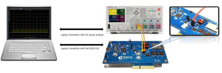
UM-WI-023
DA16200 Evaluation Kit

Contents
Abstract ................................................................................................................................................ 1
1    Terms and Definitions ................................................................................................................... 5
2    References ..................................................................................................................................... 5
3    DA16200 Module EVK ................................................................................................................... 6
4    Test Sequence ............................................................................................................................... 7
5    Wi-Fi Mode Setup .......................................................................................................................... 8
     5.1 DA16200 Connecting the Board ........................................................................................... 8
     5.2 Configure the Serial Port for UART ....................................................................................... 8
     5.3 Setup for Station Mode ......................................................................................................... 9
     5.4 Setup for Soft-AP Mode ...................................................................................................... 12
6    DPM setup .................................................................................................................................... 15
     6.1 What is DPM ....................................................................................................................... 15
     6.2 Enable DPM Mode .............................................................................................................. 15
     6.3 Hold DPM Mode .................................................................................................................. 16
     6.4 Disable DPM Mode ............................................................................................................. 17
7    Current Measurement ................................................................................................................. 19
     7.1 Test Setup ........................................................................................................................... 19
     7.2 Sleep 1 ................................................................................................................................ 19
     7.3 Sleep 2 ................................................................................................................................ 19
     7.4 Sleep 3 ................................................................................................................................ 19
8    Ping Test ...................................................................................................................................... 21
     8.1 Test Setup ........................................................................................................................... 21
     8.2 Add ARP Record ................................................................................................................. 22
     8.3 Perform Ping Test ............................................................................................................... 23
9    Throughput Test .......................................................................................................................... 24
     9.1 Test Setup ........................................................................................................................... 24
     9.2 Iperf Test with Client Mode ................................................................................................. 25
     9.3 Iperf Test with Server Mode ................................................................................................ 26
10 DA16200 Commands ................................................................................................................... 28
   10.1 Console Commands............................................................................................................ 28
        10.1.1 Root Commands .................................................................................................. 29
        10.1.2 Network Commands ............................................................................................ 29
   10.2 CLI Command ..................................................................................................................... 31
        10.2.1 Overview .............................................................................................................. 31
        10.2.2 CLI Format ........................................................................................................... 32
        10.2.3 Common Commands ........................................................................................... 32
        10.2.4 STA Commands .................................................................................................. 35
        10.2.5 Soft-AP Commands ............................................................................................. 35
        10.2.6 Advanced Commands ......................................................................................... 39
11 Firmware Update ......................................................................................................................... 39
   11.1 Flash MAP ........................................................................................................................... 39
   11.2 OTP Lock Protection ........................................................................................................... 40

User Manual                                                      Revision 2.0                                                          09-Feb-2021

CFR0012                                                                2 of 55                                          © 2021 Dialog Semiconductor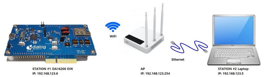
UM-WI-023
DA16200 Evaluation Kit
11.3 Bootloader Image ................................................................................................................ 41
11.4 System Library Image ......................................................................................................... 42
11.5 Main RTOS Image .............................................................................................................. 43
11.6 Download Image with Script (Macro) .................................................................................. 46
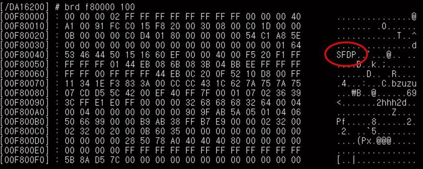
11.7 SFDP Checking ................................................................................................................... 48
11.8 Serial Flash Recovery ......................................................................................................... 48
11.9 Serial Flash Recovery from Boot ........................................................................................ 49
11.10 Boot Index Change ............................................................................................................. 51
11.11 MAC Address Checking ...................................................................................................... 51
12 Country Codes ............................................................................................................................. 52
Revision History ................................................................................................................................ 54
Figures
Figure 1: Hardware Configuration ......................................................................................................... 6
Figure 2: JTAG Pin Connection ............................................................................................................. 6
Figure 3: Test Point for Current Measurement ...................................................................................... 7
Figure 4: Check COM ports on Device Manager .................................................................................. 8
Figure 5: Serial Port Setup .................................................................................................................... 9
Figure 6: Easy Setup Start .................................................................................................................... 9
Figure 7: Country Selection ................................................................................................................. 10
Figure 8: Station mode Selection ........................................................................................................ 10
Figure 9: AP Selection ......................................................................................................................... 10
Figure 10: Check Wi-Fi Configuration ................................................................................................. 11
Figure 11: Wi-Fi Configuration Completed .......................................................................................... 11
Figure 12: Soft-AP Mode Selection ..................................................................................................... 12
Figure 13: Setup AP ............................................................................................................................ 12
Figure 14: AP Mode Selection ............................................................................................................. 13
Figure 15: AP Setup Completed .......................................................................................................... 14
Figure 16: Setting DPM Factor with Default ........................................................................................ 15
Figure 17: Setting DPM factor with User Defined ............................................................................... 16
Figure 18: DPM Mode Running after Reboot ...................................................................................... 16
Figure 19: DPM Mode Hold ................................................................................................................. 17
Figure 20: DPM Mode Off.................................................................................................................... 18
Figure 21: Current Test Environment .................................................................................................. 19
Figure 22: Current Measurement with DPM ........................................................................................ 20
Figure 23: Ping Test Environment ....................................................................................................... 21
Figure 24: Ethernet IP Address Assign ............................................................................................... 21
Figure 25: DA16200 IP Address Assign .............................................................................................. 21
Figure 26: Check ARP Record ............................................................................................................ 22
Figure 27: Interface name for ARP Record ......................................................................................... 22
Figure 28: Success ARP Record for DA16200 ................................................................................... 23
Figure 29: Ping Test with DPM ............................................................................................................ 23
Figure 30: Iperf Test Environment ....................................................................................................... 24
Figure 31: Iperf Test Command .......................................................................................................... 24
Figure 32: Check IP address ............................................................................................................... 25
Figure 33: Disable Firewall for Iperf Test ............................................................................................ 25
Figure 34: Run Iperf Server on PC ...................................................................................................... 26
Figure 35: Run iperf Client on the DA16200 ....................................................................................... 26
Figure 36: Check the IP address of DA16200 ..................................................................................... 26
Figure 37: Run Iperf Server on Terminal ............................................................................................. 27
Figure 38: Run Iperf Client on the Laptop ........................................................................................... 27
Figure 39: CLI Check ........................................................................................................................... 31
Figure 40 : run macro .......................................................................................................................... 40
User Manual Revision 2.0 09-Feb-2021
CFR0012 3 of 55 © 2021 Dialog Semiconductor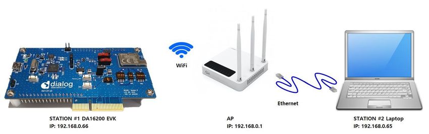
UM-WI-023
DA16200 Evaluation Kit

Figure 41 : OTP locked........................................................................................................................ 41
Figure 42: Mask ROM ......................................................................................................................... 41
Figure 43: Bootloader Prompt on Command Window ......................................................................... 42
Figure 44: Load Image File.................................................................................................................. 42
Figure 45: System Library Prompt on Command Window .................................................................. 43
Figure 46: Load Image File.................................................................................................................. 43
Figure 47: Main Image Prompt on Command Window ....................................................................... 44
Figure 48: Load Image file ................................................................................................................... 44
Figure 49: Factory Mode Prompt on Command Window .................................................................... 45
Figure 50. Load Macro ........................................................................................................................ 46
Figure 51. Download Bootloader ......................................................................................................... 46
Figure 52. Download RTOS Image ..................................................................................................... 47
Figure 53. Download Slib Image ......................................................................................................... 47
Figure 54: SFDP .................................................................................................................................. 48
Figure 55: Initialize NVRAM ................................................................................................................ 49
Figure 56: Recovery Point in the EVK ................................................................................................. 50
Figure 57: Run with BOOT mode ........................................................................................................ 50

Tables
Table 1: GPIO, SPI Selective Switch .................................................................................................... 7
Table 2: Root Commands.................................................................................................................... 29
Table 3: Network Commands .............................................................................................................. 30
Table 4: CLI Commands in Common Mode ........................................................................................ 32
Table 5: CLI Commands on STA mode .............................................................................................. 35
Table 6: CLI Commands on Soft-AP mode ......................................................................................... 35
Table 7: Advanced CLI Commands .................................................................................................... 39
Table 8: 2 MB Serial Flash Memory Map ............................................................................................ 39
Table 9: 4 MB Serial Flash Memory Map ............................................................................................ 40
Table 10: Country Codes..................................................................................................................... 52

User Manual                                                    Revision 2.0                                                      09-Feb-2021

CFR0012                                                             4 of 55                                         © 2021 Dialog Semiconductor
UM-WI-023
DA16200 Evaluation Kit

1      Terms and Definitions
DPM               Dynamic Power Management
AP                Access Point
USB               Universal Serial Bus
UART              Universal Asynchronous Receiver-Transmitter
RTC               Real Time Clock
WPS               Wi-Fi Protected Setup
SSID              Service Set Identifier
SDK               Software Development Kit
ARP               Address Resolution Protocol

2      References
[1]   DA16200, Datasheet, Dialog Semiconductor
[2]   UM-WI-002, DA16200, SDK Programmer Guide, User Manual, Dialog Semiconductor
[3]   UM-B-114, DA14531, Devkit Pro Hardware, User Manual, Dialog Semiconductor
[4]   UM-WI-012, DA16200 SPI SFlash Downloader, User Manual Rev 1v5, Dialog Semiconductor

User Manual                             Revision 2.0                              09-Feb-2021

CFR0012                                    5 of 55                     © 2021 Dialog Semiconductor
UM-WI-023
DA16200 Evaluation Kit
3 DA16200 Module EVK
Figure 1 shows the hardware configuration of the DA16200 Module Evaluation Kit (EVK).
Figure 1: Hardware Configuration
DA16200 has the following components:
1. Main board: DA16200 module (DA16200MOD-AAC4WA32) is installed on the PCI type main
board.
2. USB Interface part.
3. DA16200MOD-AAC4WA32 Wi-Fi Module.
4. USB Port: UART0 (for debug) and UART1 (for AT command).
5. JTAG PIN: to be able to connect I-jet (a JTAG debugger from IAR). See Figure 2.
a. Pin 7 on each end is keyed with a white plug, so Pin 7 should be removed on EVK.
Figure 2: JTAG Pin Connection
6. Factory Reset Button: press for more than 5 seconds to initialize nvram data.
7. WPS Button: press to start WPS mode.
8. RTC Wake up key: switch to wake up the board from Sleep Mode.
9. RTC Power key: switch to turn the board on/off.
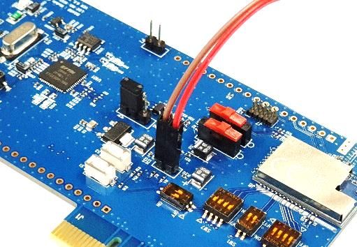
10. Pin (P2): selected part in red color is for current measurement. For normal operation, this pin
should be shorted. See Figure 3.
a. Pull out the Short Pin cap and use the jumper wire to connect to measuring equipment.
User Manual Revision 2.0 09-Feb-2021
CFR0012 6 of 55 © 2021 Dialog Semiconductor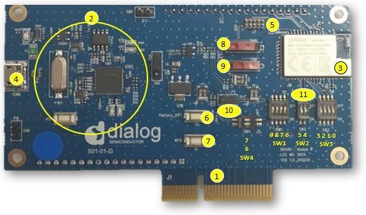
UM-WI-023
DA16200 Evaluation Kit

                          Figure 3: Test Point for Current Measurement

11. GPIO, SPI selective switch: SW2, SW3, SW4 (Default: on), SW1 (Default: off). See Table 1.
    a. For more details on how to use the pins, see the schematic of the 6.0 EVK in the manual UM-
       WI-012 DA16200 SPI SFlash Downloader Rev 1v5 [4].

Table 1: GPIO, SPI Selective Switch
    Selective Switch                     On                                    Off
 SW3 : GPIO 0, 1, 2, 3   Image download using SPI 1           Not defined
 SW2 : GPIO 4, 5         UART 1(TXD, RXD) to FT232H           UART 1 to external MCU for Test
 SW1 : GPIO 6, 7         Image download using SPI 2           WPS, Factory Reset
 SW1 : GPIO 8, 9         Image download using SPI 2           Not defined
 SW4 : GPIO 6, 7         WPS, Factory Reset                   Not defined

4     Test Sequence
This section describes the test sequence for how we show the DA16200 benefits of the following test
items:
● Current measure (Section 7)
  ○ Section 7.1 > Section 5.1, 5.2 > Section 7.2 (Sleep1), Section 7.3 (Sleep 2)
  ○ Section 7.1 > Section 5.1, 5.2 > Section 6 > Section 7.4
● Ping test (Section 7)
● Section 5.1, 5.2, 5.3 > (Section 6) > Section 7
● Throughput test (Section 9)
● Section 5.1, 5.2, 5.3 > Section 9
● SoftAP test (Section 5.4)
● Section 5.1, 5.2 > Section 5.4
● Firmware update
● Section 5.1, 5.2 > Section 11

User Manual                               Revision 2.0                                  09-Feb-2021

CFR0012                                       7 of 55                        © 2021 Dialog Semiconductor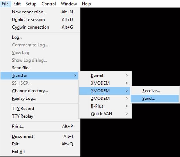
UM-WI-023
DA16200 Evaluation Kit

5       Wi-Fi Mode Setup
This section describes how to setup the Station and Soft-AP mode that are supported by DA16200.
● Station: a mode that runs the 802.11 STA interface.
● Soft-AP: a mode that runs the Software Access Point. Know that the Soft-AP mode does not
      support full-fledged commercial level Access Point features. This mode is normally used for
      Provisioning.

5.1       DA16200 Connecting the Board
This section describes the installation procedure for the drivers, the configuration of the serial port,
and all necessary steps to verify the connection with the PC as well as solutions to any problems that
may occur.
On first connection to a host PC with Microsoft Windows as operating system, the system will detect
several devices and will automatically install all necessary drivers. If not automatically installed, then
get the driver from the following url: http://www.ftdichip.com/Drivers/CDM/CDM21224_Setup.zip.
There are two virtual COM ports created by the Windows driver. The first COM port (lower number,
COM35 in this example) provides a UART interface for debugging or firmware download between the
PC and the DA161200. The second (higher number, COM36 in this example) is used for
ATCOMMAND. See Figure 4.

                           Figure 4: Check COM ports on Device Manager

5.2       Configure the Serial Port for UART
On a Windows Host the utility Tera Term is used to fully validate the connection to the DA16200
EVK. Tera Term is a free software terminal emulator (communication program) that supports multiple
communication including serial port connections. Download Tera Term from https://ttssh2.osdn.jp.
Run the teraterm-x.yy.exe executable and follow the installation wizard.
To make sure that the communication between the DA16200 EVK and the host PC is properly
established, the UART connection between the two nodes needs to be verified. For that purpose, do
the following steps:
1. Connect the DA16200 EVK to the PC via USB cable to USB Port.
2. Check if the host discovered two serial ports as shown in Figure 4. The second is connected to
   UART (see Section 5.1).
User Manual                                  Revision 2.0                                     09-Feb-2021

CFR0012                                          8 of 55                           © 2021 Dialog Semiconductor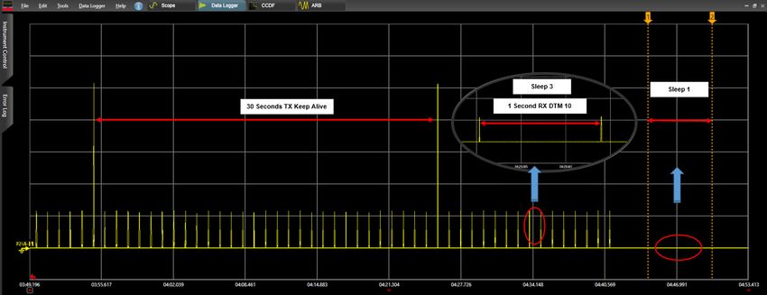
UM-WI-023
DA16200 Evaluation Kit

3. Open Tera Term from the Windows Start menu.
4. In the Tera Term: New connection dialog:
   a. Select Serial.
   b. Select the COM Port to use.
   c. Click OK.
5. Select Setup > Serial Port and configure your UART port with the parameters as shown in
   Figure 5.
6. Open the Lowest COM port number assigned to the DA16200 EVK (see Figure 4), to figure out
   which port number is used by Windows by running the Device Manager. Make sure that the
   UART is configured as shown in Figure 5.

                                       Figure 5: Serial Port Setup

5.3       Setup for Station Mode
Easy Setup is a Wi-Fi configuration wizard to easily configure the Wi-Fi functions of DA16200.
1. Run command setup.
 NOTE
 From here on, the setup query statements will continue. So please answer the questions as follows:
2. Stop all services for the setting. Are you sure? [Yes/No]: type Yes
   See Figure 6.

                                       Figure 6: Easy Setup Start

3. COUNTRY CODE? [Quit] (Default KR): type US for testing
   See Figure 7.

User Manual                                   Revision 2.0                                      09-Feb-2021

CFR0012                                           9 of 55                            © 2021 Dialog Semiconductor
UM-WI-023
DA16200 Evaluation Kit

                                   Figure 7: Country Selection

4. MODE? [1/2/Quit] (Default Station): type 1
   See Figure 8.

                                Figure 8: Station mode Selection

5. SELECT SSID? (1~30/Manual/Quit): type 1
   See Figure 9.
   a. Select the SSID of the AP to which you want to connect. If there is no AP that you want to
      connect to, please press Enter to rescan.
      For example: SSID ACST_AC_TEST2 is selected for testing.

                                      Figure 9: AP Selection

6. PSK-KEY (ASCII characters 8~63 or hexadecimal characters 64)? [Quit]
   : ******** type the password that matches the encryption method of the selected AP.
7. WIFI CONFIGURATION CONFIRM? [Yes/No/Quit]: type Y. See Figure 10.
8. IP Connection Type? [Automatic IP/Static IP/Quit]: type A
   IP is automatically assigned by DHCP.
9. IP CONFIGURATION CONFIRM? [Yes/No/Quit]: type Y

User Manual                               Revision 2.0                                  09-Feb-2021

CFR0012                                      10 of 55                        © 2021 Dialog Semiconductor
UM-WI-023
DA16200 Evaluation Kit
10. SNTP Client enable: type N
If time synchronization is not needed, then there is no need to run the SNTP Client.
11. Dynamic Power Management? [Yes/No/Quit]: type N
See section 6.1 for more information about DPM.
Figure 10: Check Wi-Fi Configuration
12. Once all settings are made as shown in Figure 10, the configuration is saved and the system will
reboot as shown in Figure 11.
Figure 11: Wi-Fi Configuration Completed
User Manual Revision 2.0 09-Feb-2021
CFR0012 11 of 55 © 2021 Dialog SemiconductorUM-WI-023
DA16200 Evaluation Kit
5.4 Setup for Soft-AP Mode
The setup for the Soft-AP mode is almost same as for the STA mode. You can also use Easy Setup
to set up the Soft-AP mode. Do the following instructions:
1. At the prompt, run command setup.
Note 1 From here on, the setup query statements will continue. So please answer the questions as follows:
2. MODE? [1/2/Quit] (Default Station): type 2
See Figure 12.
Figure 12: Soft-AP Mode Selection
3. SSID? (Default 16200_9FFFFF): TEST AP. See Figure 13.
○ Choose the SSID you want to use.
4. CHANNEL? [1~11, Auto:0/QUIT]: press [ENTER]
5. AUTHENTICATION? [1/3/4/5/QUIT]: type 4
○ WPA2-PSK is recommended
6. ENCRYPTION? [1/2/3/Quit]: type 2
7. PSK-KEY (ASCII characters 8~63 or hexadecimal characters 64)? [Quit]
: ******** Enter the password you want to use.
Figure 13: Setup AP
8. Do you want to set advanced Wi-Fi configuration? [No/Yes/Quit] (Default No): type N
See Figure 14.
9. WIFI CONFIGURATION CONFIRM? [Yes/No/Quit]: type Y
10. IP ADDRESS? [Quit] (Default 10.0.0.1): press [ENTER]
11. SUBNET? [Quit] (Default 255.255.255.0): press [ENTER]
12. GATEWAY? [Quit] (Default 10.0.0.1): press [ENTER]
13. DNS? [Quit] (Default 8.8.8.8): press [ENTER]
14. IP CONFIGURATION CONFIRM? [Yes/No/Quit]: type Y
15. DHCP SERVER CONFIGURATION? [Yes/No/Quit]: type Y
16. DHCP SERVER LEASE IP Count (MAX 10)? [Quit] (Default 10): press [ENTER]
17. DHCP SERVER LEASE TIME (60 ~ 86400 SEC)? [Quit] (Default 1800): press [ENTER]
User Manual Revision 2.0 09-Feb-2021
CFR0012 12 of 55 © 2021 Dialog SemiconductorUM-WI-023
DA16200 Evaluation Kit
18. DHCP SERVER CONFIGURATION CONFIRM? [Yes/No/Quit]: type Y
Figure 14: AP Mode Selection
User Manual Revision 2.0 09-Feb-2021
CFR0012 13 of 55 © 2021 Dialog SemiconductorUM-WI-023
DA16200 Evaluation Kit
Figure 15: AP Setup Completed
Once all settings are made, the configuration is saved, and the system will reboot.
A message is printed that Soft-AP mode started successfully. See Figure 15.
User Manual Revision 2.0 09-Feb-2021
CFR0012 14 of 55 © 2021 Dialog SemiconductorUM-WI-023
DA16200 Evaluation Kit
6 DPM setup
6.1 What is DPM
DPM (Dynamic Power Management) is a synthesis of breakthrough ultra-low power technologies that
enable extremely low power operation in the DA16200. DPM shuts down every micro element of the
chip that is not in use, which allows a near zero level of power consumption when not actively
transmitting or receiving data. Such low-power consumption can provide a battery life of one year or
more, depending on the application. DPM also enables ultra-low power transmit and receive modes
when the SoC needs to be awake to exchange information with other devices. Advanced algorithms
enable to stay asleep until the exact required moment to wake up to transmit or receive.
6.2 Enable DPM Mode
This section shows how to enable the DPM mode:
1. Do the steps in section 5.1 until step 11: Dynamic Power Management? [Yes/No/Quit].
2. At prompt Dynamic Power Management? [Yes/No/Quit]: type Y. See Figure 16.
a. To use the default DPM factor, DPM factors: Defaults? [Yes/No/Quit], type Y
b. DPM CONFIGURATION CONFIRM [Yes/No/Quit]: type Y
NOTE
TIM wakeup count 10 dtim is the default value. This means: 10dtim*102.4 = 1,024 ms = 1sec @ DTIM = 1 (in
case that AP DTIM = 3, 10dtim is 921.6 ms)
Wake-up from sleep state takes place every 1 seconds to check for a receive packet
Figure 16: Setting DPM Factor with Default
c. To use user-defined DPM factor, DPM factors: Defaults? [Yes/No/Quit], type N. See
Figure 17.
i. DPM Keep Alive Time (0~600000 ms)? [Quit] (Default 30000 ms): press [ENTER]
or type value within range
ii. DPM User Wakeup Time (0~86400 Sec.)? [Quit] (Default 0 Sec.): press [ENTER]
or type value within range
iii. DPM TIM Wakeup Count (1~65535 dtim)? [Quit] (Default 10): press [ENTER] or
type value within range
iv. DPM CONFIGURATION CONFIRM [Yes/No/Quit]: type Y
User Manual Revision 2.0 09-Feb-2021
CFR0012 15 of 55 © 2021 Dialog SemiconductorUM-WI-023
DA16200 Evaluation Kit
Figure 17: Setting DPM factor with User Defined
3. After reboot, DA16200 will enter DPM sleep. The print message >>> Start DPM Power-
Down!!! means that DA16200 has entered DPM Sleep. See Figure 18.
Figure 18: DPM Mode Running after Reboot
NOTE
After the system starts running with DPM, user input via the UART will not work from that moment.
6.3 Hold DPM Mode
Once the system starts running with DPM, user input via the UART does not work anymore from that
moment. This is because the UART interface is down during DPM Sleep, which is normal. To exit
this state and start over with setup, do the following instructions:
1. Copy the string dpm hold to the clipboard.
a. For example: open Notepad, type dpm hold, and then copy (Ctrl + C) the command string.
2. Use RTC_PWR_KEY to power off (move to OFF position).
3. Use RTC_PWR_KEY to power on (move to ON position).
4. Before the message >>> Start DPM Power-Down !!! is printed on the console, quickly do the
following:
a. With the dpm hold string copied, right-click in the terminal window to paste the string.
b. Immediately press the ENTER key.
c. Once this procedure is done quickly and successfully, the message DPM Sleep Manager
HOLD… is printed. See Figure 19.
d. If the DPM mode does not stop successfully, you may need to retry several times.
5. Run setup again to configure DA16200 in a different mode.
User Manual Revision 2.0 09-Feb-2021
CFR0012 16 of 55 © 2021 Dialog SemiconductorUM-WI-023
DA16200 Evaluation Kit
Figure 19: DPM Mode Hold
6.4 Disable DPM Mode
Though we make DPM enabled during setup, we can disable DPM mode with command dpm off at
the prompt. DA16200 will be reboot and connect to AP as shown in Figure 20.
User Manual Revision 2.0 09-Feb-2021
CFR0012 17 of 55 © 2021 Dialog SemiconductorUM-WI-023
DA16200 Evaluation Kit
Figure 20: DPM Mode Off
User Manual Revision 2.0 09-Feb-2021
CFR0012 18 of 55 © 2021 Dialog SemiconductorUM-WI-023
DA16200 Evaluation Kit
7 Current Measurement
For more detailed information on Sleep mode, please see section 'Low Power Operation Mode' in
DA16200 Datasheet [1]. To measure the current waveform, connect EVK's current measurement
point (P2) with the measurement instrument (KEYSIGHT 14585A).
7.1 Test Setup
Figure 21 shows a typical test setup environment.
Figure 21: Current Test Environment
7.2 Sleep 1
To measure the Sleep 1 current, use RTC_PWR_KEY to power off (move to OFF position). See
Section 3, number 9. See Figure 22.
7.3 Sleep 2
To measure the Sleep 2 current, the following command is required:
1. Use RTC_PWR_KEY to power on (move to on position). See section 3, number 9.
2. Type command factory to make DA16200 use the default setting.
3. The board will reboot.
4. At prompt, run command sleep 2 time(sec) [/DA16200/SYS.HAL] # sleep 2 time(sec)
○ For instance, [/DA16200/SYS.HAL] # sleep 2 10
○ It will sleep for a set amount of time (10 seconds), and then reboot and wake
up.
7.4 Sleep 3
1. Do the steps in Section 6.2 until step 3.
○ When you run the DA16200 with DPM settings, DA16200 will run DPM Sleep, wake up for
Beacon check and Keep Alive according to the configured DTIM
For example: the current waveform in Figure 22 shows settings DTIM 10 (about 1sec @ AP DTIM=1)
and Keep Alive 30s.
Sleep 3 current means current between RX or between RX and TX.
User Manual Revision 2.0 09-Feb-2021
CFR0012 19 of 55 © 2021 Dialog SemiconductorUM-WI-023
DA16200 Evaluation Kit
Figure 22: Current Measurement with DPM
User Manual Revision 2.0 09-Feb-2021
CFR0012 20 of 55 © 2021 Dialog SemiconductorUM-WI-023
DA16200 Evaluation Kit
8 Ping Test
DA16200 has command ping to verify communication test (Ping Test) during DPM mode.
8.1 Test Setup
For a communication test (Ping Test) there are two stations (DA16200 and Laptop) and an Access
Point (AP) required. Both must be connected to the same sub-network AP. See Figure 23. DA16200
must be connected to the AP via WIFI, and the laptop must be connected to the AP with an Ethernet
cable. After configuration, DA16200 will be in DPM Sleep mode (sleep 3). Then DA16200 can wake
up from sleep mode when unicast packets are sent, while remaining in sleep mode most of the time.
In this test, a Ping application that runs on the laptop acts as a network peer that sends a unicast
packet to DA16200. This is to check if DA16200 in DPM Sleep mode can successfully wake up and
receive the unicast packets in real-time.
Figure 23: Ping Test Environment
1. Run the command window (CMD) as administrator.
2. Type command ipconfig to see what the IP address is of the laptop. See Figure 24.
For example: the laptop's IP is 192.168.0.65, and the Default Gateway IP is 192.168.0.1
Figure 24: Ethernet IP Address Assign
3. Run the DA16200 terminal window and set DA16200 in Station mode (see Section 5.3).
○ For example: the assigned IP of DA16200 is 192.168.0.66. See Figure 25.
Figure 25: DA16200 IP Address Assign
User Manual Revision 2.0 09-Feb-2021
CFR0012 21 of 55 © 2021 Dialog SemiconductorUM-WI-023
DA16200 Evaluation Kit
8.2 Add ARP Record
This section describes how to add a DHCP assigned IP address to the ARP table and to change that
IP address from a dynamic to a static IP address.
Since retransmission logic is not included in the higher protocol (TCP / UDP), an additional ARP
record is required for ping tests between the laptop and the DA16200 operating in DPM sleep mode.
1. Use command arp -s 192.168.0.66 ec-9f-f9-32 to add an ARP record manually.
NOTE
When you set the ARP cache to static with command arp -s on higher versions of Windows, you may get an
error like Failed to add ARP entry, Access is denied.
It is recommended to use command netsh to change the network settings
Do the following steps to change the ARP record to a static IP address:
2. Use command arp -a to view ARP table of the network interface. See Figure 26.
○ For example: C:\WINDOWS\system32>arp -a
Figure 26: Check ARP Record
3. Use command netsh interface show interface to find the interface name. See Figure 27.
○ For example: C:\WINDOWS\system32>netsh interface show interface
Figure 27: Interface name for ARP Record
4. Use the interface name found for DA16200 to set the ARP cache to static with command
C:\WINDOWS\system32> netsh interface ipv4 add neighbors "" ""
"". See Figure 28.
○ For example: C:\WINDOWS\system32> netsh interface ip add neighbors "Ethernet"
"192.168.0.66" "ec-9f-0d-9f-f9-32"
5. Use command arp -a on the laptop to check if the ARP cache is configured correctly. See Figure
28.
○ For example: C:\WINDOWS\system32>arp -a
○ DA16200’s IP address 192.168.0.66 is added to ARP table as a static type
User Manual Revision 2.0 09-Feb-2021
CFR0012 22 of 55 © 2021 Dialog SemiconductorUM-WI-023
DA16200 Evaluation Kit
Figure 28: Success ARP Record for DA16200
6. Use command arp -d or netsh interface ip delete arpcache to initialize the ARP cache.
8.3 Perform Ping Test
Ping application is a simple generic application provided by Network Stack for network management
purposes. Its main purpose is to check if a node is alive in the same sub network. Ping just sends out
a request once and then waits for a reply. Ping prints the result only if a Reply packet arrives from the
peer.
1. Make DPM enable. See Section 6.2.
2. Run a ping on the Laptop. See Figure 29.
For example: C:\WINDOWS\system32>ping 192.168.0.66 -t
Next, DA16200 wakes up and receives the ping message, sends a reply and goes to DPM sleep
again.
Figure 29: Ping Test with DPM
NOTE
If you have multiple network interfaces enabled, then put the arp entry under the specific interface.
For example: arp -s 192.168.20.52 aa-ff-00-88-66-80 –S 192.168.100.100
192.168.100.100 is the interface from which the ping command should be sent. In this case, specifying
network interface is required in the ping command.
For example: ping 192.168.20.52 –S 192.168.100.100
User Manual Revision 2.0 09-Feb-2021
CFR0012 23 of 55 © 2021 Dialog SemiconductorUM-WI-023
DA16200 Evaluation Kit
9 Throughput Test
DA16200 has command iperf to measure the packet transfer performance. This is known as the
throughput test. To do the throughput test, prepare the DA16200 to operate in Station mode (see
Section 5.1) without using DPM (see Section 6.4). This section shows the throughput test with the
use of a TCP client / server protocol.
9.1 Test Setup
Figure 30: Iperf Test Environment
The Iperf tool should be ready on your laptop. Iperf Version 2.0.9 is recommended.
Do the following steps to setup Iperf tool:
1. Download Iperf from https://iperf.fr/iperf-download.php.
2. Create a folder called Iperf in path C:\
3. Unzip the downloaded file and move the contents to the Iperf folder.
4. Prepare the DA16200 to operate in Station mode. See Sections 5.1 to 5.3.
5. Use command iperf or iperf -h to see the available options in Iperf. See Figure 31.
○ For example: [/DA16200/NET] # iperf
Figure 31: Iperf Test Command
User Manual Revision 2.0 09-Feb-2021
CFR0012 24 of 55 © 2021 Dialog SemiconductorUM-WI-023
DA16200 Evaluation Kit
9.2 Iperf Test with Client Mode
To set-up the Iperf test with Client mode, do the following steps:
1. Connect the laptop you want to use as a server to the AP.
2. In the CMD window, use command ipconfig/all to find the IP address. See Figure 32.
Figure 32: Check IP address
NOTE
The IP address can be different depending on the home AP setting.
3. For stable Iperf testing, run the Windows Security APP to turn off the network firewall.
○ It is recommended to disable the laptop from all network firewalls before attempting a test.
See Figure 33.
Figure 33: Disable Firewall for Iperf Test
4. In the CMD window, move to the directory where Iperf is installed, and type iperf -s to
configure the TCP server.
User Manual Revision 2.0 09-Feb-2021
CFR0012 25 of 55 © 2021 Dialog SemiconductorUM-WI-023
DA16200 Evaluation Kit
Figure 34: Run Iperf Server on PC
NOTE
When you see the message as shown in Figure 34, the Iperf test is ready to start.
5. In the DA16200 console window, run the Iperf test with Client mode. See Figure 35.
○ For example: [/DA16200/NET] #iperf -I wlan0 -c 192.168.123.5 -t 5 -i 1
– The format of the command type is:
– iperf -I [INTERFACE] [-s/-c] [DESTINATION IP] (-u) -i [INTERVAL TIME] -t
[TEST TIME]
Figure 35: Run iperf Client on the DA16200
9.3 Iperf Test with Server Mode
A server mode test should be run with a configuration that is opposite to that of client mode. In this
case, the DA16200 is prepared as a server. The laptop becomes a client and sends data to the
DA16200.
1. In the DA16200 console window, please check the assigned IP address for DA16200 as shown
in Figure 36.
Figure 36: Check the IP address of DA16200
2. Run the Iperf test with Server mode on the DA16200 console window. See Figure 37.
○ For example: [/DA16200/NET] # iperf -I wlan0 -s
User Manual Revision 2.0 09-Feb-2021
CFR0012 26 of 55 © 2021 Dialog SemiconductorUM-WI-023
DA16200 Evaluation Kit
Figure 37: Run Iperf Server on Terminal
3. In the CMD window, run the Iperf test with Client mode. See Figure 38.
○ For example: C:\iperf>iperf -c 192.168.123.6 -t 5 -i 1
Figure 38: Run Iperf Client on the Laptop
User Manual Revision 2.0 09-Feb-2021
CFR0012 27 of 55 © 2021 Dialog SemiconductorUM-WI-023 DA16200 Evaluation Kit 10 DA16200 Commands The DA16200 has various console commands to operate its functions. The UART0 interface connects the console with a serial terminal tool. Some commands in the following sections may be disabled according to the SDK’s features configuration. 10.1 Console Commands The DA16200 console commands are categorized as follow: ● root ○ [/DA16200] # ● mem ○ [/DA16200/MEM] # ● sys ○ [/DA16200/SYS] # ● nvram ○ [/DA16200/NVRAM] # ● net ○ [/DA16200/NET] # ● user ○ [/DA16200/USER] # Use command help or ? (Question mark) to list the available commands and options. There is a function to display the console command history, and up to 5 commands can be saved. Use the following keys and characters to access the history function: ● ↑ or ↓ (arrow key) on your keyboard: show the command history one by one. ● ! (Exclamation mark): view the list of the command history. ● ! (Exclamation mark) + Number: select and execute one previous command in the list. It is possible to move between categories. Use these options: ● top: move to the highest-rank, root. ● up: move to one step upper rank category. ● Category command (for example sys, nvram, net): move to the category. To run each commands of each category, go to the category first, or prefix the category name to the command as shown in the example: ○ net ○ net.ifconfig User Manual Revision 2.0 09-Feb-2021 CFR0012 28 of 55 © 2021 Dialog Semiconductor
UM-WI-023
DA16200 Evaluation Kit

10.1.1     Root Commands

Table 2: Root Commands
  Command          Parameters                                        Description
 help /?       (none)               Display help information for the corresponding category
 up            (none)               Move up one rank category
 top           (none)               Move to the Root category
 factory       (none)               Factory reset for all settings
 ps            (none)               Display thread information
                                    DA16200 general function setting wizard (Easy Setup)
 setup         (none)               Make step-by-step configuration settings for elements such as
                                    SYSMODE, WI-FI, and NETWORK
               (none)               Reboot
 reboot
               [mode]               ● por: POR rebooting
 reset         (none)               Reset to the Bootloader prompt
 ver           (none)               Display SDK version & system information
                                    Display or set the current time.
                                    ●   time set [YYYY-MM-DD] [hh:mm:ss]: set date and time
                                    ●   time zone [-hh:mm]: set time zone
 time          [option]
                                    ●   time boot: display booting time
                                    ●   time uptime: display booting duration
                                    ●   time help: display help
 getwlanmac    (none)               Display the MAC address for network interfaces

               [xx:xx:xx:xx:xx:xx   Set up the MAC address for network interfaces.
 setwlanmac    | xx-xx-xx-xx-xx-    For example: setwlanmac aa:bb:cc:00:00:02 | aa-bb-cc-00-00-
               xx |xxxxxxxxxxxx]    02 | aabbcc000002
                                    Set DPM condition
                                    ●   on | off: DPM feature enable or disable
                                    ●   status: DPM Status print

 dpm           [options]            ●   rtm: view DPM backup data
                                    ●   rtc: view DPM RTC timer
                                    ●   debug [level]: turn DPM debug on / off
                                        ○ level = 1(MSG_ERROR), 2(MSG_INFO), 3(MSG_DEBUG),
                                           4(MSG_EXCESSIVE)

10.1.2     Network Commands
To move to the network command category, type the command net.

User Manual                              Revision 2.0                                         09-Feb-2021

CFR0012                                      29 of 55                              © 2021 Dialog Semiconductor
UM-WI-023
DA16200 Evaluation Kit
Table 3: Network Commands
Command Parameter Description
Display or set the basic network setting and status
● ifconfig: display basic network settings information
● ifconfig –a: display details of all network interfaces
● ifconfig [wlan0|wlan1]: display details of a network interface
● ifconfig [wlan0|wlan1] [ipaddress] [subnet] [gateway]: set
(none) static IP addresses to a network interface
[interface ● ifconfig [wlan0|wlan1] dhcp: enable/Disable DCHP to a
ifconfig network interface
wlan0|wlan1]
[options] ● ifconfig [wlan0|wlan1] [up|down]: go Up/Down a network
interface
● ifconfig [wlan0|wlan1] [start|stop|renew|release]: DHCP
client command
● ifconfig [wlan0|wlan1] [dns] [DNS ServerIP]: set DNS server
address (static IP) to a network interface
● ifconfig help: display help
Ping test to the target address with a certain option
● [interface wlan0|wlan1]:
○ Network interface. With no designated interface, an interface
for a subnet band of the same destination IP address is
-I [interface designated
wlan0|wlan1] ● [count]: the count of ping tests
[domain|ip] -n ● [size]: the size of data to be transmitted (max.: 10000)
ping [count] -l
[size] -w ● [timeout]: waiting time for a response to the transmitted message
[timeout] -i (min.: 10 ms)
[interval] ● [interval]: waiting time for a message transmission (min.:
10 ms)
● [-6]: ping test with an IPv6 address
For example: ping 172.16.0.1 -l 1024 -n 10 -w 1000 -i 1000
ping -6 fe80::1:2 -I wlan0
Display the ARP table of a network interface
[interface] ● a: display the ARP table of every interface
arp
[options] ● d: delete all of ARP table
● Help: Help display
[interface] Transmit the ARP request message of the target IP
arpsend [dst
ipaddress] For example: arpsend wlan0 10.0.0.1
Transmit a GARP message with option:
[interface] ● 0: normal garp
garpsend
[option] ● 1: check IP conflict
For example: arpsend wlan0
User Manual Revision 2.0 09-Feb-2021
CFR0012 30 of 55 © 2021 Dialog SemiconductorUM-WI-023
DA16200 Evaluation Kit
Command Parameter Description
DHCP server setting
● boot [on|off]: automatic start setting with a certain interface
● range : IP lease band
setting (max. 10)
[interface] ● lease_time : lease time setting (min. 60 sec.)
dhcpd
[options] ● dns : lease IP DNS server address setting
● response_delay : time of response delay
● status: display DHCP Server status
● lease [0|1]: display IP lease table
○ Display tables including un-allotted tables when flag = 1
-I [interface]
iperf [-s|-c host] Setup Iperf client/server
[options]
cli [options] Refer to the CLI section
Execute various types of debug commands
● arp [on|off]: arp debug message output on/off
● dhcpd [level]: DHCP Server debug level setting (level=0~2
debug [options] default 0)
● dhcpc [level]: DHCP Client debug level setting (level=0~5
default 1)
● umac [on|off] mask: debug umac 1 0x4
act [on | off] Start or stop DPM Auto Configuration
10.2 CLI Command
10.2.1 Overview
The DA16200 supplicant plays a key role in providing users with Wi-Fi functionality. Major functions
include IEEE 802.11 management frame, various security functions (WPA & RSN by IEEE 802.11i)
and CLI (Command Line Interface) to control DA16200 Wi-Fi performance.
The CLI in DA16200 can execute commands in the network command state.
For example, in the Station mode, the network information of DA16200 is obtained with CLI
command: [/DA16200/NET] cli status. See Figure 39.
Figure 39: CLI Check
User Manual Revision 2.0 09-Feb-2021
CFR0012 31 of 55 © 2021 Dialog SemiconductorUM-WI-023
DA16200 Evaluation Kit
10.2.2 CLI Format
There are four CLI formats (Type A~D):
● Read/Write Parameter (Type A)
○ Read: [/DA16200/NET] # cli [CLI]
○ Write: [/DA16200/NET] # cli [CLI]
● Write Only Parameter (Type B)
○ [/DA16200/NET] # cli [CLI] or cli [CLI]
● Read Only Parameter (Type C)
○ [/DA16200/NET] # cli [CLI] or cli [CLI]
● Execution Parameter (Type D)
○ [/DA16200/NET] # cli [CLI] or cli [CLI] < OPTION>
10.2.3 Common Commands
Table 4: CLI Commands in Common Mode
CLI Parameter Description
Get the main information on the interface being operated at DA16200
status (none)
For example: [/DA16200/NET] # cli status
Save all parameters modified through CLI, etc. in NVRAM
(Saved values become applicable after a reboot) (D)
For example: [/DA16200/NET] # cli save_config
* Information saved in NVRAM may be inquired with the following command:
save_co For example:
(none) [/DA16200/NVRAM] # printenv
nfig
Total length (95)
country_code (STR,03) ........ KR
SYSMODE (STR,02) ............. 0
0: NETMODE (STR,02) ........... 1
N0_Profile (STR,02) .......... 1
N0_ssid (STR,16) ............. "ACST_AC_TEST1"
Execute a motion in a certain mode (STA access, AP operation, etc.) (D)
● STA: 0 | AP: 1
For example: [/DA16200/NET] # cli select_network 0
○ Implement STA access
* For a certain mode through the select_network CLI, the following tasks need
select_ to be carried out first:
network
○ add_network (profile generation)
○ SSID generation through set_network
○ For AP operation, set up the frequency and country code values with
command set_network
○ For Security, generate WPA or WEP key values with command
set_network (option)
Generate a specific mode (STA, AP) Profile (access information table) (D)
add_net : 0(STA) | 1(AP)
work For example: [/DA16200/NET] # cli add_network 1
○ Generate a profile for AP Mode
User Manual Revision 2.0 09-Feb-2021
CFR0012 32 of 55 © 2021 Dialog SemiconductorUM-WI-023
DA16200 Evaluation Kit
CLI Parameter Description
Delete a certain mode (STA, AP) profile (D)
remove_ : 0(STA) | 1(AP)
network For example: [/DA16200/NET] # cli remove_network 1
○ Delete a profile for AP Mode
Set parameter values for a specific mode (STA, AP) (B)
: 0(STA) | 1(AP)
: a specific parameter
● ssid: [STA] Operation SSID for AP SSID / [AP] AP interface to be
connected
● psk: passphrase or PSK values
● proto: for WPA use, set up the version ( |
| )
● key_mgmt: key management mode ( | | )
● pairwise: unicast data message encryption mode ( | |
)
● group: broadcast data message encryption mode ( | |
)
● wep_key#: WEP key (#:0~3) values
● wep_tx_keyidx: WEP key index to be used
● frequency: [AP] Operation Frequency (MHz)
set_net
● mode: Operation Mode |
work
● Wi-Fi_mode: | | | | |
● beacon_int: [AP] Beacon transport interval
● dtim_period: [AP] DTIM interval
● ap_power: [AP] Output Power (dBm)
● isolate: 'Isolate' Use ( | )
● -disabled: automatic profiling prevented upon rebooting ( |
)
: settings for a certain variable
For example: [/DA16200/NET] # cli set_network 1 ssid ‘DA16200_AP’
○ For DA16200 AP operation, SSID= DA16200_AP setting
For example: [/DA16200/NET] # cli set_network 1 beacon_int 200
○ For DA16200 AP operation, Beacon interval 20 ms setting
For example: [/DA16200/NET] # cli set_network 0 key_mgmt WPA_PSK
○ For DA16200 STA operation, access in the WPA PSK security mode
* A profile needs to be generated with command add_network so that a profile
can be set with command set_network (with no profile, 'FAIL')
Get specific parameter values for a specific mode (STA, AP) (C)
: 0(STA) | 1(AP)
: a specific parameter
get_net
For example: [/DA16200/NET] # cli set_network 0 ssid
work
○ Inquiry of an object subject to DA16200 STA access (“TEST_BED_AP”)
For example: [/DA16200/NET] # cli set_network 1 psk
○ For DA16200 AP operation, inquiry of the PSK password setting
User Manual Revision 2.0 09-Feb-2021
CFR0012 33 of 55 © 2021 Dialog SemiconductorUM-WI-023
DA16200 Evaluation Kit
CLI Parameter Description
Set a country related to channel operation (A)
: Country Code that meets ISO 3166-1 alpha-2 standards
Default: KR
country For example: [/DA16200/NET] # cli country US
○ Set the Country Code to US
For example: [/DA16200/NET] # cli country
○ KR
flush (none) For every interface (STA, AP), DA16200 deletes the Profile and closes
DA16200 service operation (D)
User Manual Revision 2.0 09-Feb-2021
CFR0012 34 of 55 © 2021 Dialog SemiconductorUM-WI-023
DA16200 Evaluation Kit
10.2.4 STA Commands
Table 5: CLI Commands on STA mode
Command Parameters Description
Active scanning (Probe Request Broadcast) (D)
For inputs, it is possible to scan APs of a certain frequency
(none) or
scan range (MHz) only (option)
For example: [/DA16200/NET] # cli scan
○ Scans all channels that correspond to the current country setting
Disconnect the accessed AP (D)
disconnect (none) For example: [/DA16200/NET] # cli disconnect
○ OK (With no AP being accessed, 'FAIL')
Roaming On/Off and Roaming status inquiry (A)
run: On | stop: Off
Default: Roaming Off
(none) or For example: [/DA16200/NET] # cli roam
roam
○ Roaming=STOP, Threshold=-65
○ Usage: cli roam [run/stop]
For example: [/DA16200/NET] # cli roam stop
○ Roaming function-off
Roaming triggering RSSI value (dBm) setting (B)
: Roaming threshold RSSI (dBm)
roam_threshold Default: -65 (dBm)
For example: [/DA16200/NET] # cli roam_threshold -85
○ Set the roaming threshold to -85 dBm
10.2.5 Soft-AP Commands
Table 6: CLI Commands on Soft-AP mode
Command Parameter Description
AP interface beginning/closing/restarting (Applicable with no reboot
after main info. modification of AP interface SSID, PSK, etc.) (D)
: start | stop | restart
For example: [/DA16200/NET] # cli ap start
○ AP interface initiating (If it is being operated, 'FAIL')
For example: [/DA16200/NET] # cli ap stop
○ AP interface closing (If not being operated, 'FAIL')
ap
For example: [/DA16200/NET] # cli set_network 1 ssid
‘DA16200_AP2’
For example: [/DA16200/NET] # cli ap restart
○ Modify SSID of the interface of AP being operated
For example: [/DA16200/NET] # cli set_network 1 pairwise TKIP
For example: [/DA16200/NET] # cli ap restart
○ Modify the AP interface encryption mode to TKIP
User Manual Revision 2.0 09-Feb-2021
CFR0012 35 of 55 © 2021 Dialog SemiconductorUM-WI-023
DA16200 Evaluation Kit
Command Parameter Description
Modify the AP interface operation channel (B)
: AP operation channel (1~14) or frequency (MHz)
For example: [/DA16200/NET] # cli ap_chan_switch 3
ap_chan_switch
○ Modify the AP interface channel to 3 (242 MHz)
For example: [/DA16200/NET] # cli ap_chan_switch 11 2462
○ Modify the AP interface channel to 11 (2462 MHz)
Get main information about the interface at DA16200 (C)
For example:
[/DA16200/NET] # cli ap_status
state=ENABLED
phy=fc9k_phy0
freq=2472
num_sta_non_erp=0
num_sta_no_short_slot_time=0
ap_status (none) num_sta_no_short_preamble=0
olbc=0
num_sta_ht_no_gf=0
num_sta_no_ht=0
num_sta_ht_20_mhz=0
num_sta_ht40_intolerant=0
olbc_ht=0
ht_op_mode=0x0
cac_time_seconds=0
cac_time_l
Output the list information of STA being accessed to the AP interface
(C)
For example:
[/DA16200/NET] # cli all_sta
50:77:05:DB:C4:3E
flags=[AUTH][ASSOC][AUTHORIZED][SHORT_PREAMBLE][WMM
aid=1
capability=0x431
all_sta (none)
listen_interval=10
mode = 802.11n
timeout_next=0
rx_packets=632
tx_packets=9
rx_bytes=67451
tx_bytes=4767
connected_time=77
sta_count=1
The deauthenticate message is transmitted to the access STA with a
certain MAC address to cancel the access (D)
: MAC address of the access STA
deauthenticate
For example: [/DA16200/NET] # cli deauthenticate
aa:ff:01:00:00:00
○ Transmit the de-authentication message to STA whose MAC
address is AA:FF:01:00:00:00
The disassociation message is transmitted to the access STA with a
certain MAC address to cancel the access (D)
: MAC address of the access STA
disassociate For example: [/DA16200/NET] # cli disassociate
aa:ff:01:00:00:00
○ Transmit the disassociation message to STA whose MAC
address is AA:FF:01:00:00:00
User Manual Revision 2.0 09-Feb-2021
CFR0012 36 of 55 © 2021 Dialog SemiconductorUM-WI-023
DA16200 Evaluation Kit
Command Parameter Description
WMM function availability setting and inquiry (A)
: On: 1 | Off: 0
wmm_enabled Default: Off
For example: [/DA16200/NET] # cli wmm_enabled 1
○ Use the WMM function
WMM-PS function availability setting and inquiry (A)
: On: 1 | Off: 0
wmm_ps_enabled Default: Off
For example: [/DA16200/NET] # cli wmm_ps_enabled 1
○ Use the WMM-PS function
Set up details of DA16200 AP or STA's certain category WMM
parameters (B)
: ap | sta
: be(best-effort) | bk(background) | vi(video) | vo(voice)
For example: [/DA16200/NET] # cli wmm_params ap be 3 15 63 10
wmm_params
○ For WMM AP's best-effort category, AIFS=3, CWmin=15,
For example: [/DA16200/NET] # cli wmm_params sta vo 4 7 15 60
○ For WMM STA's voice category, AIFS=4, CWmin=7,
CWmax=15, TXOP_Limit=60
Inquiry of all parameters that can be set up by means of wmm_params
all_wmm (none) CLI (C) (See example)
For example: [/DA16200/NET] # cli all_wmm
Add the MAC address to the Access Control Management List (B)
: AP MAC Address
acl_mac
For example: [/DA16200/NET] # cli acl_mac AA:FF:01:00:00:06
○ Add MAC address AA:FF:01:00:00:06 to ACL
Set up, delete, or inquire the use of ACL (A)
: allow | deny | clear | delete (If none, inquire of it)
: AP MAC Address (only when oper=”delete”)
[/DA16200/NET] # cli acl [allow/deny/clear/delete mac_address]
For example: [/DA16200/NET] # cli acl
For example: [/DA16200/NET] # cli acl allow
Acl
○ Access allowed only for AP Lists in ACL
For example: [/DA16200/NET] # cli acl deny
○ Access denied only for AP Lists in ACL
For example: [/DA16200/NET] # cli acl clear
○ Entire ACL clear
For example: [/DA16200/NET] # cli delete aa:ff:01:00:00:08
○ Delete AA:FF:01:00:00:08 from ACL
User Manual Revision 2.0 09-Feb-2021
CFR0012 37 of 55 © 2021 Dialog SemiconductorYou can also read