SNAP-2 (SOIL NAIL ANALYSIS PROGRAM) - User's Manual Publication No. FHWA-HIF-14-016
←
→
Page content transcription
If your browser does not render page correctly, please read the page content below
SNAP-2 (SOIL NAIL ANALYSIS PROGRAM)
User’s Manual
Publication No. FHWA-HIF-14-016   September 2014
FOREWORD

The current design process for soil nail earth retention systems is inefficient because multiple
tools are needed for facing, internal/external, and global design. These tools do not
communicate with one another, and are often used by different staff members. The main
objective of this work is to develop a single State-of-Practice computer program for designing
the entire soil nail earth retaining structure, including nail elements, facing elements, global
stability, and evaluation of internal and external wall stability based on the current AASHTO
design standards. By combining all these assessment tools into one package, we take another
step towards assuring high quality and efficient designs and accelerating project delivery.

                                              Amy Lucero
                                              Director, Office of Technical Services

                                             Notice
This document is disseminated under the sponsorship of the U.S. Department of Transportation
in the interest of information exchange. The U.S. Government assumes no liability for the use of
the information contained in this document.

The U.S. Government does not endorse products or manufacturers. Trademarks or
manufacturers’ names appear in this report only because they are considered essential to the
objective of the document.

                                  Quality Assurance Statement
The Federal Highway Administration (FHWA) provides high-quality information to serve
Government, industry, and the public in a manner that promotes public understanding. Standards
and policies are used to ensure and maximize the quality, objectivity, utility, and integrity of its
information. FHWA periodically reviews quality issues and adjusts its programs and processes to
ensure continuous quality improvement.

                                                 i
TECHNICAL REPORT DOCUMENTATION PAGE

1. Report No.              2. Government Accession No.           3. Recipient’s Catalog No.
FHWA-OTS-XXX
4. Title and Subtitle                                            5. Report Date
SNAP-2 (Soil Nail Analysis Program)                              March 2014
User’s Manual                                                    6. Performing Organization Code:

7. Author(s)                                                     8. Performing Organization Report No.
Barry D. Siel, P.E.
9. Performing Organization Name and Address                      10. Work Unit No.
FHWA Resource Center
12300 W. Dakota Ave. #340                                        11. Contract or Grant No.
Lakewood, CO 80228                                               N/A
12. Sponsoring Agency Name and Address                           13. Type of Report and Period Covered
Office of Technical Services                                     N/A
Federal Highway Administration                                   14. Sponsoring Agency Code
12300 W. Dakota Ave. #340                                        OTS
Lakewood, CO 80228
15. Supplementary Notes
N/A
16. Abstract

        Soil nail walls are internally stabilized earth-retaining structures. Soil nail walls use a top-down
     construction with in situ reinforcement to support temporary or permanent excavations. In certain
     conditions, soil nailing is a viable alternative to other ground anchor systems, considering technical
     feasibility, cost, and construction duration.
        Although the use of soil nail walls for highway applications has increased dramatically in the past
     decade, computer programs for the design of soil nail walls are not up to date. The main objective of this
     work is to develop a state-of-the-practice computer program, SNAP-2 (Soil Nail Analysis Program) for
     designing all components of soil nail retaining structures, including nail and facing elements. The program
     will evaluate the internal and external wall stability (including limit-equilibrium global slope stability)
     based on the current standards in the ASD method. In addition, the program may be used to evaluate
     verification and proof field test results. All design and evaluation procedures are according to the FHWA
     guidelines presented in 1) The Manual for Design and Construction of Soil Nail Walls, Report No. FHWA-
     SA-96- 069R, and 2) Geotechnical Engineering Circular No. 7 - Soil Nail Walls, Report No. FHWA-IF-03-
     017.
         This user’s manual discusses the theoretical basis for the computer program, gives a comparison of
     available soil nail wall design guidelines, discusses program execution including inputs and outputs, and
     includes two worked examples to demonstrate use of the program.

17. Key Words                                           18. Distribution Statement
Soil Nails, SNAP-2                                      No restrictions. This document is available through the
                                                        National Technical Information Service, Springfield, VA
                                                        22161.
19. Security Classif. (of this report)   20. Security Classif. (of this page)   21. No. of Pages     22. Price
Unclassified                             Unclassified                           Insert No. here      N/A
Form DOT F 1700.7 (8-72)                                                  Reproduction of completed page authorized

                                                          ii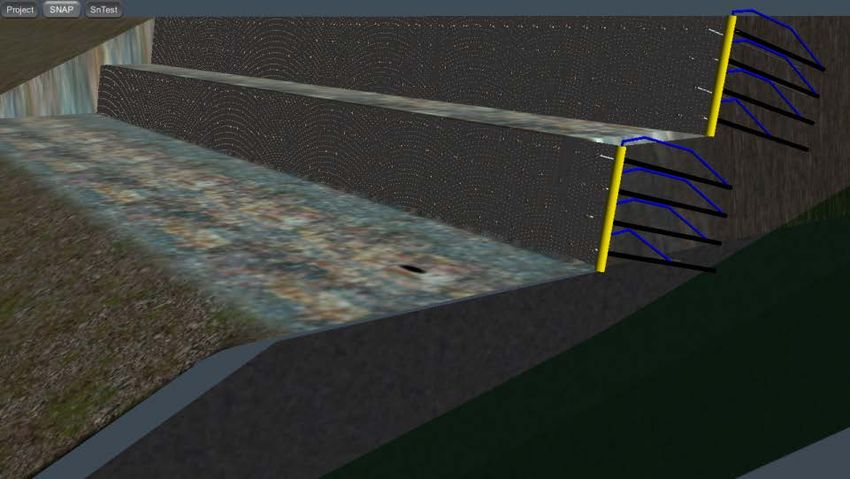
SI* (MODERN METRIC) CONVERSION FACTORS
APPROXIMATE CONVERSIONS TO SI UNITS
Symbol When You Know Multiply By To Find Symbol
LENGTH
in inches 25.4 millimeters mm
ft feet 0.305 meters m
yd yards 0.914 meters m
mi miles 1.61 kilometers km
AREA
2 2
in square inches 645.2 square millimeters mm
2 2
ft square feet 0.093 square meters m
yd2 square yard 0.836 square meters m2
ac acres 0.405 hectares ha
2 2
mi square miles 2.59 square kilometers km
VOLUME
fl oz fluid ounces 29.57 milliliters mL
gal gallons 3.785 liters L
ft3 cubic feet 0.028 cubic meters m3
3 3
yd cubic yards 0.765 cubic meters m
3
NOTE: volumes greater than 1000 L shall be shown in m
MASS
oz ounces 28.35 grams g
lb pounds 0.454 kilograms kg
T short tons (2000 lb) 0.907 megagrams (or "metric ton") Mg (or "t")
TEMPERATURE (exact degrees)
o o
F Fahrenheit 5 (F-32)/9 Celsius C
or (F-32)/1.8
ILLUMINATION
fc foot-candles 10.76 lux lx
2 2
fl foot-Lamberts 3.426 candela/m cd/m
FORCE and PRESSURE or STRESS
lbf poundforce 4.45 newtons N
lbf/in2 poundforce per square inch 6.89 kilopascals kPa
APPROXIMATE CONVERSIONS FROM SI UNITS
Symbol When You Know Multiply By To Find Symbol
LENGTH
mm millimeters 0.039 inches in
m meters 3.28 feet ft
m meters 1.09 yards yd
km kilometers 0.621 miles mi
AREA
mm2 square millimeters 0.0016 square inches in2
2 2
m square meters 10.764 square feet ft
2 2
m square meters 1.195 square yards yd
ha hectares 2.47 acres ac
2 2
km square kilometers 0.386 square miles mi
VOLUME
mL milliliters 0.034 fluid ounces fl oz
L liters 0.264 gallons gal
m3 cubic meters 35.314 cubic feet ft3
3 3
m cubic meters 1.307 cubic yards yd
MASS
g grams 0.035 ounces oz
kg kilograms 2.202 pounds lb
Mg (or "t") megagrams (or "metric ton") 1.103 short tons (2000 lb) T
TEMPERATURE (exact degrees)
o o
C Celsius 1.8C+32 Fahrenheit F
ILLUMINATION
lx lux 0.0929 foot-candles fc
2 2
cd/m candela/m 0.2919 foot-Lamberts fl
FORCE and PRESSURE or STRESS
N newtons 0.225 poundforce lbf
2
kPa kilopascals 0.145 poundforce per square inch lbf/in
*SI is the symbol for the International System of Units. Appropriate rounding should be made to comply with Section 4 of ASTM E380.
(Revised March 2003)
iii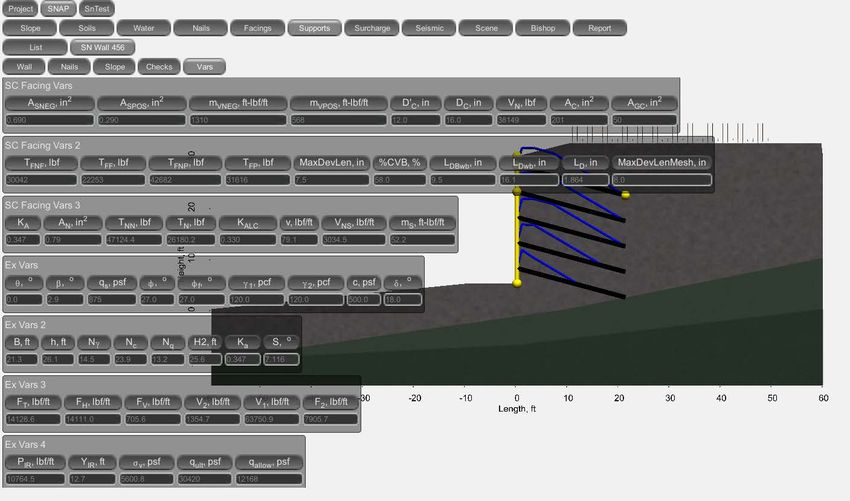
TABLE OF CONTENTS

CHAPTER 1 – PURPOSE AND SCOPE OF SNAP-2 .............................................................. 1
    INTRODUCTION................................................................................................................... 1
         Background ....................................................................................................................... 1
         Comparison to GOLDNAIL and SNAIL Programs ...................................................... 1
         Basic Theory ...................................................................................................................... 1
         Wall Facing Analysis ........................................................................................................ 2
         Internal Stability Analysis................................................................................................ 2
         External Stability Analysis ............................................................................................... 2
         Global Stability Analysis .................................................................................................. 4
         Groundwater ..................................................................................................................... 5
         Program Installation ......................................................................................................... 6

CHAPTER 2 – INPUT PARAMETERS..................................................................................... 7
    SNAP-2 CONVENTIONS ...................................................................................................... 7
         File Management ............................................................................................................... 7
         Program Capabilities ........................................................................................................ 7
         Tabs and Option Selection ............................................................................................... 7
         Geometry ........................................................................................................................... 8
         Data Entry ......................................................................................................................... 8
    PROGRAM EXECUTION .................................................................................................... 8
         Getting Started .................................................................................................................. 8
    SNAP-2 DATA ENTRY TABS .............................................................................................. 8
         Project - Select ................................................................................................................... 8
         Project – Settings............................................................................................................... 9
         SNAP – Slope ................................................................................................................... 10
         SNAP – Image ................................................................................................................. 10
         SNAP – Soils .................................................................................................................... 11
         SNAP – Water ................................................................................................................. 13
         SNAP – Nails ................................................................................................................... 14
         SNAP - Facings ................................................................................................................ 15
         SNAP – Supports............................................................................................................. 18

                                                                     iv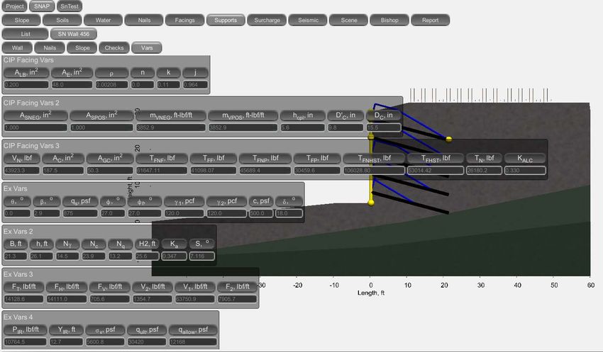
SNAP – Supports - Wall ................................................................................................. 18
         SNAP - Supports – Nails................................................................................................. 20
         SNAP – Supports – Slope ............................................................................................... 21
         SNAP – Surcharge .......................................................................................................... 22
         SNAP - Seismic ................................................................................................................ 22
         SNAP – Supports – Checks ............................................................................................ 23
         SNAP - Supports - Vars .................................................................................................. 25
         SNAP - Scene ................................................................................................................... 26
         SNAP – Bishop ................................................................................................................ 27
         SNAP – Report ................................................................................................................ 29
         SnTest – List .................................................................................................................... 30
         SnTest – Verification/Proof - Design ............................................................................. 30
         SnTest – Verification/Proof – Test ................................................................................ 31
         SnTest – Verification/Proof – Creep Movement .......................................................... 32
         SnTest – Verification/Proof – Creep Rate .................................................................... 33
         SnTest – Verification/Proof – Report ............................................................................ 34

CHAPTER 3 – DESIGN EXAMPLE ........................................................................................ 35
    SNAP-2 APPLICATION ...................................................................................................... 35
         Geometry ......................................................................................................................... 35
         Soils Data ......................................................................................................................... 36
         Groundwater ................................................................................................................... 36
         Nails .................................................................................................................................. 37
         Facings ............................................................................................................................. 37
         Supports ........................................................................................................................... 39
         Surcharge ......................................................................................................................... 40
         Seismic .............................................................................................................................. 41
         Bishop ............................................................................................................................... 41
         Design Checks.................................................................................................................. 42
         Scene ................................................................................................................................. 42
         Report............................................................................................................................... 42

                                                                       v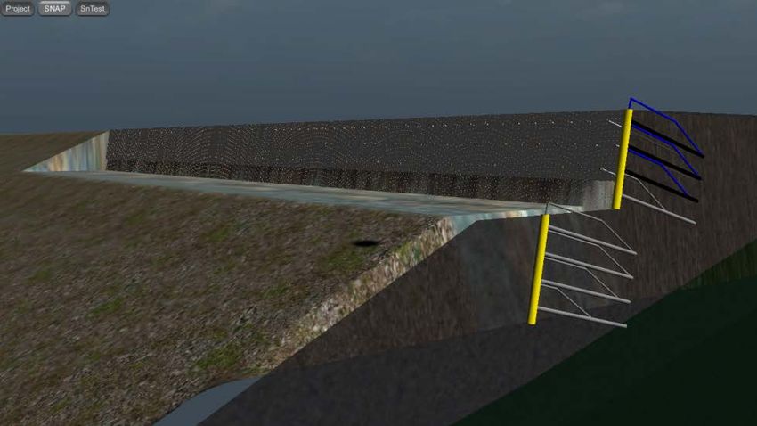
APPENDIX A – SELECTION OF NAIL LENGTHS ............................................................. 43
APPENDIX B DESIGN EXAMPLE REPORT ....................................................................... 47
     SNAP-2 REPORT ................................................................................................................. 47
BIBLIOGRAPHY ....................................................................................................................... 67

                                                                  vi
LIST OF FIGURES
Figure 1 Schematic. Nail Support Diagram used in SNAP-2.................................................... 3
Figure 2. Schematic. Wall base length, B, used for external stability calculations ................. 4
Figure 3. Schematic. Method of pore pressure calculation in SNAP-2 .................................... 5
Figure 4. Screen Shot. Opening screen, Project – Select ........................................................... 9
Figure 5. Screen Shot. Project – Settings .................................................................................... 9
Figure 6. Screen Shot. SNAP – Slope ........................................................................................ 10
Figure 7. Screen Shot. SNAP – Image ....................................................................................... 11
Figure 8. Screen Shot. SNAP - Soils – Settings......................................................................... 11
Figure 9. Screen Shot. SNAP - Soils - Soil 2 ............................................................................. 12
Figure 10. Screen Shot. SNAP - Water ..................................................................................... 13
Figure 11. Screen Shot. SNAP - Nails ....................................................................................... 14
Figure 12. Screen Shot. SNAP – Facings – List........................................................................ 15
Figure 13. Screen Shot. SNAP – Facings –Temporary Facing ............................................... 16
Figure 14. Screen Shot. SNAP – Facings – Permanent Facing ............................................... 17
Figure 15. Screen Shot. SNAP – Supports - List ...................................................................... 18
Figure 16. Screen Shot. SNAP – Supports - Wall .................................................................... 19
Figure 17. Screen Shot. SNAP – Supports - Nails .................................................................... 20
Figure 18. Screen Shot. SNAP – Supports - Slope ................................................................... 21
Figure 19. Screen Shot. SNAP - Surcharge .............................................................................. 22
Figure 20. Screen Shot. SNAP - Seismic ................................................................................... 23
Figure 21. Screen Shot. SNAP – Supports – Checks – SC ...................................................... 24
Figure 22. Screen Shot. SNAP – Supports – Checks - CIP ..................................................... 24
Figure 23. Screen Shot. SNAP – Supports – Vars – SC .......................................................... 25
Figure 24. Screen Shot. SNAP – Supports – Vars - CIP ......................................................... 26
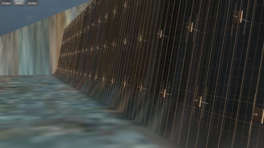
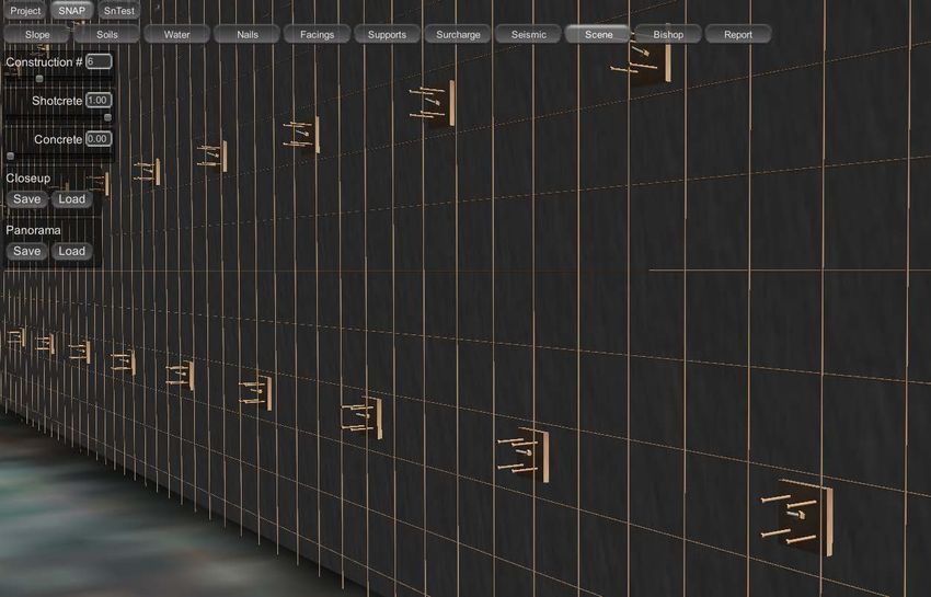
Figure 25. Screen Shot. SNAP –Scene - Closeup...................................................................... 27
Figure 26. Screen Shot. SNAP – Scene – Panorama ................................................................ 27
Figure 27. Screen Shot. SNAP – Bishop - Static ...................................................................... 28
Figure 28. Screen Shot. SNAP – Bishop - Seismic ................................................................... 28
Figure 29. Screen Shot. SNAP – Report ................................................................................... 29
Figure 30. Screen Shot. SnTest – List ....................................................................................... 30
Figure 31. Screen Shot. SnTest – Verification – Design .......................................................... 30
vii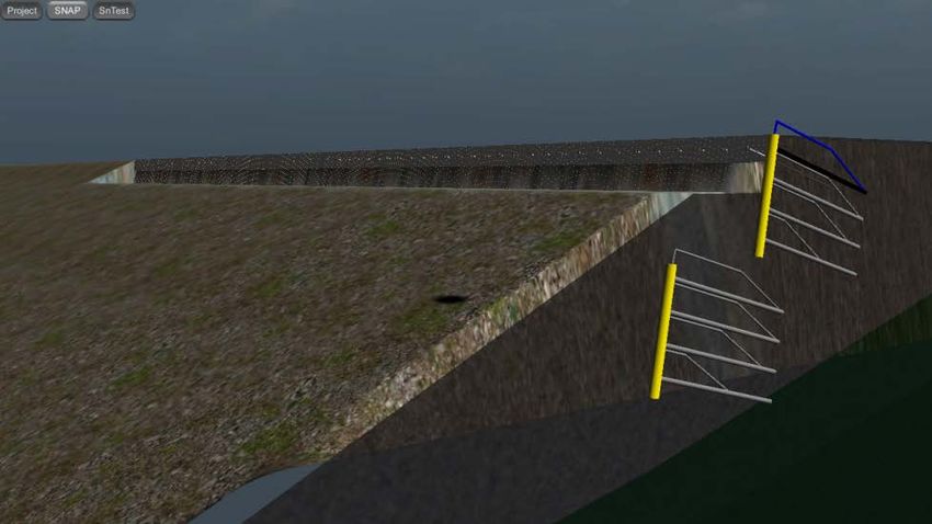
Figure 32. Screen Shot. SnTest – Verification – Test .............................................................. 31
Figure 33. Screen Shot. SnTest – Verification – Creep Movement ........................................ 32
Figure 34. Screen Shot. SnTest – Verification – Creep Rate .................................................. 33
Figure 35. Screen Shot. SnTest – Verification – Report.......................................................... 34
Figure 36. Screen Shot. Design Example 1 ............................................................................... 35
Figure 37. Screen Shot. X and Y coordinates for original ground surface points ................ 35
Figure 38. Screen Shot. Soil properties ..................................................................................... 36
Figure 39. Screen Shot. X and Y coordinates for top of Dense SAND ................................... 36
Figure 40. Screen Shot. X and Y coordinates for top of groundwater................................... 36
Figure 41. Screen Shot. Factors of safety for tendon rupture and pullout capacity
    Tendon dimensions and yield strength ............................................................................. 37
Figure 42. Screen Shot. Names and descriptions of facings .................................................... 37
Figure 43. Screen Shot. Input for temporary facing................................................................ 38
Figure 44. Screen Shot. Input for permanent facing ............................................................... 38
Figure 45. Screen Shot. Names and descriptions for each wall tier ....................................... 39
Figure 46. Screen Shot. Construction and wall dimensions for upper wall .......................... 39
Figure 47. Screen Shot. Construction and wall dimensions for lower wall ........................... 39
Figure 48. Screen Shot. Nail parameters .................................................................................. 40
Figure 49. Screen Shot. Displacement parameters .................................................................. 40
Figure 50. Screen Shot. Surcharge location and magnitude ................................................... 40
Figure 51. Screen Shot. Seismic loading parameters ............................................................... 41
Figure 52. Screen Shot. Critical failure surface and global factor of safety.......................... 41
Figure 53. Schematic. Unsuitable nail layout that satisfies global stability requirements ... 43
Figure 54. Schematic. Suitable nail layout that satisfies global stability requirements ....... 44
Figure 55. Schematic. Reduction of soil nail lengths in the lower part of the wall ............... 45
Figure 56. Schematic. Determination of the value “R” to be used in Figure 55 ................... 46

                                                             viii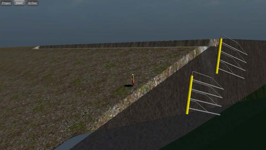
LIST OF ACRONYMS AND ABBREVIATIONS
A          Peak ground acceleration due to seismic loading
AASHTO     American Association of State Transportation Officials
aw         Angle between phreatic surface and horizontal
ASD        Allowable Stress Design
B          Wall base length
c          Soil cohesion
CalTrans   California Department of Transportation
CIP        Cast-in-place
DOS        Disk Operating System
DTL        Design test load
FHWA       Federal Highway Administration
ft         foot (feet)
ft2        square feet
ft3        cubic feet
FS         Factor of Safety
Fy         Steel yield strength
GEC        Geotechnical Engineering Circular
H          Wall height
hw         Vertical distance between failure surface and phreatic surface
in         inches
in2        square inches
Ka         Active earth pressure coefficient
kh         Horizontal seismic coefficient
kip        kilo pound (1000 pounds)
kN         kilo Newton(s), SI unit of force
kPa        kilo Pascal
kv         Vertical seismic coefficient
lb         pounds of mass
lbf        pounds of force
LRFD       Load Resistance Factor Design
m          meter
m2         square meters
m3         cubic meters
MSE        Mechanically Stabilized Earth
Nc         Bearing capacity factor
Nq         Bearing capacity factor
Nγ         Bearing capacity factor
psi        pounds per square inch
SI units   International System of units (e.g. m, N, kPa, etc.)
SNAP-2     Soil Nail Analysis Program
US units   United States customary units (e.g., ft, lbf, psi, etc.)
φ          Internal friction angle of a soil
γ          Soil unit weight

                                            ix
CHAPTER 1 – PURPOSE AND SCOPE OF SNAP-2
INTRODUCTION
Background
Because of the advantages of soil nail walls, the Federal Highway Administration (FHWA) has
sponsored and coordinated the development of several technical reports and research on soil nail
wall projects since the early 1990s (see Appendix A – References for a list of FHWA soil nail
publications).
The objective of this document is to present SNAP-2 (Soil Nail Analysis Program), a computer
program that follows the current FHWA guidelines for designing a soil nail earth retaining
structure. This includes the design of all soil nail system components such as 1) nail elements, 2)
facing elements, 3) external stability, and 4) global stability. All design and evaluation
procedures were developed in general accordance with the FHWA guidelines presented in
Geotechnical Engineering Circular No. 7 – Soil Nail Walls (GEC 7), Report No. FHWA-XX-
XX-XXX.
SNAP-2 follows the current allowable stress design guidelines, including internal and external
stability evaluation for static and seismic loading. External failure modes include global
stability, sliding, and bearing capacity analysis. Internal failure modes include nail pullout and
nail tensile failure analysis, along with nail head and facing element analysis for temporary and
permanent conditions.
Comparison to GOLDNAIL and SNAIL Programs
Although the use of soil nailing for highway applications has increased dramatically, computer
programs for designing soil nail walls have not kept pace with the industry. For the last 20 years,
two soil nail specific computer programs were available for determining the length and
specifications of the nail components. SNAIL (DOS-based, developed by CalTrans, 1991) and
GOLDNAIL (Windows based, developed by Golder and Associates, 1993) were the primary soil
nail specific computer programs available for the designer. Both programs have limited use and
are mainly designed for checking the soil nail wall stability by varying nail types and sizes,
spacing and bond strengths. Neither program is capable of designing wall facing elements,
shotcrete, or evaluating the global stability of the wall system with a complex slope profile.
Because SNAP-2 (all computer programs) uses a limit equilibrium design method, soil nail walls
are designed using ASD (allowable stress design). Some programs, such as GOLDNAIL allow
for the input of resistance factors (LRFD), but internally the program inverses the resistance
factors and uses them as safety factors in an ASD design.
Basic Theory
SNAP-2 can evaluate the internal (facing and nail) components of a soil nail wall, external
stability, and global stability. The calculations are based primarily on GEC 7. The following
sections discuss how each of these components is evaluated, and how groundwater is treated
within the program.
1Wall Facing Analysis
SNAP-2 can evaluate the internal stability of a soil nail wall for both shotcrete-only facing type
and permanent cast-in-place (CIP) concrete facing types. Calculations are based on GEC 7.
For a shotcrete-only facing, SNAP-2 determines the nominal nail head strength by evaluating
flexure and punching shear failure modes, based on input from the user. SNAP-2 will calculate
the nominal nail head strength for both failure modes, and use the critical value in subsequent
global stability calculations. Input parameters include information on the wire mesh, horizontal
waler and vertical bearing bars, bearing plate, and shotcrete. Permanent applications of shotcrete
facing can be troweled to an acceptable façade or faced with pre-cast panels. For a cast-in-place
facing type, typically soil nail walls are constructed with a temporary shotcrete facing. Then the
permanent CIP concrete facing is installed and connected to the nails by headed studs on the
bearing plates, after completion of the temporary wall facing. When a final facing is evaluated in
SNAP-2 (CIP concrete or shotcrete) the strength of the temporary shotcrete facing is neglected
under the assumption that the temporary facing strength cannot be relied upon in the long-term.
In addition to flexure and punching shear failure modes, headed stud tension failure is evaluated
for a permanent facing. The program will calculate the nominal nail head strength for all three
failure modes in the permanent facing, and use the critical value in global stability calculations.
Input parameters include information on CIP concrete or shotcrete, mesh (if used), horizontal
and vertical reinforcement bars, and the headed-stud connection system.
In addition to determining the nail head strength, SNAP-2 performs required design and
serviceability checks for both shotcrete and CIP facings as outlined in GEC 7.
Internal Stability Analysis
SNAP-2 evaluates maximum nail loading along the length of each nail using methods outlined in
GEC 7. This method is based on applying the Coulomb active earth load uniformly at the back
of the wall facing. The program uses the nail head strength determined from the facing analysis,
the nail tendon strength entered by the user, the grout-ground pullout strength entered by the
user, and the factors of safety entered by the user to generate a nail support diagram for each nail
(Figure 1). SNAP-2 then uses the nail support diagram for each nail in the global stability
calculations. For each slip circle evaluated for global stability, the program determines the nail
loads at the locations where the slip circle intersects each nail, according to each nail’s support
diagram. These loads are applied to their respective slices in the global FS calculations for each
slip circle.
External Stability Analysis
External stability of a retaining structure refers to the potential failure or deformation modes
typically associated with conventional gravity or cantilever retaining structures. These failure
modes include horizontal sliding of the retaining wall along its base, and foundation bearing
failure of the retaining wall associated with overturning. The “slip surface” limiting equilibrium
technique, does not entail separate evaluation for sliding stability or overturning stability about
the toe of the wall; these failure modes are accounted for in the general slip surface evaluation,
which also includes global stability analysis. Foundation bearing failure is evaluated separately,
but a complete evaluation is not required for all soil conditions. SNAP-2 performs a complete
bearing capacity evaluation for all cases, rather than the rough initial check outlined in GEC 7.
Sliding failure along the base of the wall and overturning about the toe of the wall are also
2evaluated, based on FHWA guidelines for Mechanically Stabilized Earth (MSE) walls. These
failure modes are highly unlikely to control stability of a soil nail wall, and are provided
primarily for the designer’s own information and conformance with AASHTO.
Figure 1 Schematic. Nail Support Diagram used in SNAP-2 (FHWA SA-96-069R)
SNAP-2 includes the effects of seismic forces in external stability calculations if the user
inputs required seismic information. Seismic forces are taken into account by including, in
addition to the static forces, a horizontal inertial force and a dynamic horizontal thrust force. The
dynamic horizontal thrust is calculated using the Mononobe-Okabe method (Mononobe, 1929;
Okabe, 1926). This method is applicable to all values of the friction angle, φ, and introduces an
additional angle into the calculations for the active earth pressure coefficient, Ka, based on the
horizontal and vertical seismic coefficients. The user input for seismic loading can either be the
peak ground acceleration, A, or the horizontal seismic coefficient, kh. SNAP-2 allows the user to
input the vertical seismic coefficient, kv, which is used for both external and global stability
calculations.
For all external stability calculations, the passive earth pressure behind the nailed soil mass is
calculated using Coulomb’s earth pressure coefficient. The wall-soil interface friction angle is
taken to be 2/3 of the friction angle, φ. The surface on which passive earth pressure acts (the
back surface of the wall) is assumed to always be vertical. SNAP-2 evaluates external stability
for the long-term drained case rather than short-term undrained case; therefore, saturated unit
weight of the reinforced soil and groundwater uplift forces are not incorporated into the external
stability calculations.
Sliding stability is evaluated along the base of the nailed soil mass. The base width of the wall is
taken as the horizontal distance between the toe of the wall and the average end of the nails
(Figure 2). This method allows the calculation to be consistent whether the user selects uniform
3or non-uniform nail geometry. The cohesive strength of the foundation soil is included in the
resisting forces, but not the shear strength of any nails that may extend below the base of the
wall. Overturning (moment) stability is evaluated about the toe of the wall, at the ground
surface. Although this is not generally considered for soil nail walls, it has been included for the
wall designer’s information and conformance with AASHTO. This failure mode is highly
unlikely to control stability of a soil nail wall.
Figure 2. Schematic. Wall base length, B, used for external stability calculations (FHWA CFL/TD-10-004)
Bearing capacity is evaluated using the method outlined in GEC 7. The user must enter bearing
capacity factors Nc, Nγ, and Nq, on the Soil input tab, or choose to have the program calculate
the bearing capacity factors from the friction angle input by the user. This allows the user to
adjust the bearing capacity calculation to account for sloping ground in front of the wall. At this
time, groundwater below the base of the wall is not accounted for in the ultimate bearing
capacity calculations; if groundwater is anticipated below the soil nail wall, SNAP-2 accounts for
this condition in the global stability evaluation.
Global Stability Analysis
SNAP-2 evaluates limit-equilibrium global stability using Bishop’s Simplified (Modified)
Method. This method accounts for interslice normal forces but ignores interslice shear forces,
and satisfies vertical force equilibrium for each slice and overall moment equilibrium about the
center of the slip circle. SNAP-2 can evaluate circular-shaped failure surfaces only. The soil
mass is divided into approximately 100 slices, and stability is assessed for an average of 5,000
slip circles to find the most critical failure surface and associated factor of safety (FS). SNAP-2
can evaluate stability under seismic loading conditions using a pseudo-static analysis, by
including the weight of each slice, reduced by the horizontal seismic coefficient, in the sum of
forces and moments. The slip circles for which SNAP-2 calculates a FS are generated
automatically by the program. Slip circle centers are located above the top nail and to the left of
4(down-slope of) the wall face. Circle center points are on a grid with a spacing that is scaled
along with the height of the wall.
The global stability calculation includes surcharge loading, nail support loads, pseudo-static
seismic loads (if selected), and uplift force at the base of each slice due to groundwater. The
added weight of water due to saturated soil is not factored.
The user can specify the minimum height of the failure circle arc to remove small failure circles.
The failure surface search algorithm is very robust so that potential failure surfaces, both outside
and inside (passing through some or all of the soil nails) the reinforced soil mass are checked.
This failure surface is not restricted to pass through the wall facing therefore, it may pass below
the wall and exit in front of the wall facing. The program will show the critical failure surface
(the lowest factor of safety) that encounters the reinforced soil mass. If the critical failure
surface does not encounter the reinforced soil mass, that failure surface will also be displayed.
Groundwater
SNAP-2 utilizes a phreatic surface groundwater model (Figure 3). The pore pressure from any
point is computed from the difference in head between that point and the phreatic surface. Figure
3 illustrates a phreatic pore pressure calculation. SNAP-2 only uses pore water pressure for
calculating global stability. The additional weight of saturated soil below the phreatic surface is
not accounted for, however – only the uplift force at the base of each slice due to pore water
pressures. SNAP-2 can only accommodate an unconfined aquifer groundwater model.
Groundwater is not accounted for in facing, internal, or external stability calculations, including
bearing capacity.
Figure 3. Schematic. Method of pore pressure calculation in SNAP-2 (FHWA CFL/TD-10-004)
5Program Installation
The SNAP-2 computer program is installed by running the executable program SNAP-
2_setup_2013 and following the directions in the Setup Wizard. In the Setup Wizard, the user
will select a location for the folder (SNAP-2) that will be installed and contains all the files and
subfolders for the SNAP-2 program. The default location is “C:\Programs\SNAP-2,” but the
user can browse to select any location on their computer. The Setup Wizard will also create a
shortcut in the Start Menu and an icon on the desktop.
6CHAPTER 2 – INPUT PARAMETERS
SNAP-2 CONVENTIONS
File Management
SNAP-2 does not include conventional file management capability. When a new project is
created, files will be created and saved automatically in a folder with the same name as the
project. If a user wants to make changes to a project without losing the previous data for the
project, the original project file can be opened and , without exiting SNAP-2, a new name can be
entered (in the Project – Select screen). Appropriate changes can then be made to the project
description, material properties and/or geometry. The changes will be saved automatically in a
new folder with the new project name.
Program Capabilities
In addition to the standard entry of geometrical and material properties for the ground and soil
nails, SNAP-2 requires entry of the facing design parameters including dimensions and strength
values for reinforcement, concrete or shotcrete, and facing connections. SNAP-2 calculates the
facing strength capacity in flexure and punching for temporary and permanent facing, and the
headed stud connection for permanent facing. SNAP-2 allows for complicated slopes, multiple
soil nail walls, multiple soil layers, and multiple temporary and permanent facing designs. This
allows for the flexibility of assigning different facing designs for each wall. SNAP-2 displays a
2-dimensional graphical representation of the data. The graphical display is updated as values
are entered into the data boxes.
Tabs and Option Selection
Input parameters in SNAP-2 are organized into a series of tabs and sub-tabs. In addition to the
tabs, some options can be changed by clicking on radio buttons or moving sliders. Radio buttons
can be toggled between active and inactive status by clicking on the dot, when a radio button is
active the dot appears white. The sliders can be moved by placing the mouse icon on the slider
and holding down the left mouse button. For example: in the Soils tab, the user can activate a
radio button to have the program calculate the bearing capacity factors from the user provided
soil friction angle and; in the Slope tab, the user can adjust the scale and reposition the graphical
display by clicking and holding the slider and moving it back and forth.
When the mouse icon is placed on any tab, button, or slider, a banner appears across the bottom
of the screen with a description for that tab, button, or slider. In some cases, information
concerning value or dimensional checks that the program performs automatically will be
described in the bottom banner. Tabs that include these automatic checks will display a blue ball
if the check is satisfied or a yellow triangle if the check is not satisfied. When the mouse icon is
placed anywhere on the graphical display, the X and Y coordinates are displayed in the bottom
banner. The data boxes may have both active and inactive dialog boxes. Active dialog boxes
allow for the direct entry of data and appear brighter, while the inactive dialog boxes contain
values that the program calculates, data cannot be entered directly, and the inactive dialog boxes
appear duller. Data is entered into active data boxes by clicking on the box and typing in the
data. Some of the data boxes may partially block the view of the graphical display, however the
data boxes may be turned off and on by clicking on the associated tab.
7Geometry
In SNAP-2, the soil nail wall face is on the left, with the global failure occurring from right to
left on the screen. The coordinate system in SNAP-2 is 2-dimensional where the X-axis is
horizontal and the Y-axis is vertical. There is no restriction on where the wall(s) can be placed
on the coordinate grid. Both positive and negative coordinates are allowed.
Data Entry
The coordinates for points defining the location of slopes, soil layers, groundwater, wall facings,
soil nails, and surcharge loads are listed as data boxes with the points shown on the graphical
display. Points can be added by either clicking on the plus sign (+) tab on the lower left in the
data box or clicking on the graphical display. Coordinates can then be typed into the data box or
the point can be moved into position on the graphical display by placing the mouse icon on the
point and holding down the left mouse button. A new point or the active point will be displayed
pink and the point number will be highlighted in the data box. The active point can be selected
by either clicking on the point number in the data box or the point shown on the graphical
display. Points can be deleted by either clicking on the point number or on the point shown on
the graphical display (making it the active point), and then hitting the Delete key. When a new
project is initiated, the screens are preloaded with default values that can then be changed or
added to as required.
PROGRAM EXECUTION
Getting Started
Click on the desktop icon to start SNAP-2. The program will take a few seconds to start up. A
“splash-screen” is displayed during program initialization each time the program runs. The
program initially loads showing the Project tab and Select sub-tab. Clicking on the down arrow
in either the Project or Archive date box will reveal a list of previously entered projects. For an
immediate example of how the program looks and works, select Example 1 from the Project list
and then click through the tabs as outlined below.
SNAP-2 DATA ENTRY TABS
Project - Select
Either type a project name in the Project dialog box or click on the Project down arrow to open
the dropdown list of active projects and click the appropriate project name (Figure 4). To move
an active project to the Archive list, click the X next to the project name. Click on the Archive
down arrow to open the dropdown list of archived projects. Move an archived project to the
active project list by clicking on the name, or remove a project from the archived projects list
(permanently deleted) by clicking on the X next to the name. Click on the Help tab to play a
tutorial that was recorded in Windows Media Player. Once a project is selected, press the Enter
key to begin entering data.
8Figure 4. Screen Shot. Opening screen, Project – Select
Project – Settings
Either US or SI units can be selected in the Units data box (Figure 5). (At any time this selection
can be switched between US and SI units and all the data will automatically be converted). In the
Project Description data box, information about the project and soil nail wall can be input. This
information will be included in the report header. Click on the SNAP tab to begin entering
geometric data.
Figure 5. Screen Shot. Project – Settings
9SNAP – Slope
A graphical display with horizontal and vertical scales is shown with points and lines that define
the slope surface (Figure 6). The graphical display is updated as data about the ground
conditions and wall configuration are input or changed.
Click on the plus sign (+) to add points to define the original ground slope prior to construction
of the soil nail wall. In addition to the coordinate point entry methods described above in Data
Input, the X and Y coordinates can be imported to the Surface Points data box by coping data
from an excel file and then clicking the Paste Points tab. The X and Y coordinates can be
exported by clicking on the Copy Points tab and then pasting the coordinates into an excel file.
The size and position of the graphical display can be modified by using the sliders in the Scale
and Center data boxes. The Scale slider will make the graphical display larger or smaller. The
two Center sliders move the graphical display horizontally and vertically. Click on the Soils tab
to enter soils data.
Figure 6. Screen Shot. SNAP – Slope
SNAP – Image
To aid in entering slope and wall cross section information, there is an option to import an image
over which coordinate points can be placed (Figure 7). Click in the Image tab to select a .png
file to import onto the screen. The image will need to be a .png file that has been saved to the
folder which is given in the Path data box.
10Figure 7. Screen Shot. SNAP – Image
SNAP – Soils
Click on the plus sign (+) tab in the Soils data box to add a soil layer (multiple soil layers can be
defined as seen in Figure 8). Click on the soil number in the Soils data box and press the Delete
key to delete a soil layer. Soil layers are listed in order, with the stratigraphically highest soil
layer first and the stratigraphically lowest soil layer last. Click on a Name dialog box and type in
a Name such as Silty SAND or Clayey SILT. Click on the Texture down arrow and select a
texture for each soil layer from the drop down menu. The texture selection only affects the way
the soil layer is shown in the graphical display. Type the soil parameters for each soil layer (unit
weight, friction angle, cohesion, and ultimate bond strength) into the dialog boxes. The wall-
interface friction angle is calculated as 2/3 of the soil friction angle. The bearing capacity factors
for each soil layer can be typed into the dialog boxes or the user can activate the radio button in
the Calc Bearing Capacity Factors data box to have the program calculate them from the friction
angles.
Figure 8. Screen Shot. SNAP - Soils – Settings
11When more than one soil layer is defined, tabs for each additional soil layer appear to the right of
the Settings tab. Clicking on a soil layer tab will cause a data box to appear where coordinate
points defining the top of the soil layer may be input (Figure 9). (Note: The Surface Slope is the
top of the first soil layer.) Points are added in the same manner as discussed above. The
graphical display will show the points with lines separating two soil layers and the program will
assign each soil layer a color. Click on the Water tab to enter data on the groundwater level.
Figure 9. Screen Shot. SNAP - Soils - Soil 2
12SNAP – Water
Click on the plus sign (+) in the Points data box to add points (Figure 10). If the groundwater
level is not included in the problem then no points are added. Coordinate points for the
groundwater level can also be copied to and from an excel file as described in SNAP - Slope.
The groundwater level is shown on the graphical display as a series of blue lines between points.
Click on the Nails tab to enter data on bar tendon sets.
Figure 10. Screen Shot. SNAP – Water
13SNAP – Nails
Click on the plus sign (+) in the Nails data box to define a bar tendon set (Figure 11). Multiple
bar tendon sets can be defined when bar tendons that vary in size or yield strength will be used
on the project being analyzed. To delete a bar tendon set, click on the bar tendon number in the
Soils data box and press the Delete key. For each bar tendon set enter the name (default is Bar 1,
Bar 2, etc.); the diameter (D) of the drill hole; the outside diameter (Dout) of the bar tendon or
alternatively, the bar tendon size or number (Bar No, Bar #; these two values are linked); and the
yield strength of the bar tendon (Fy). For hollow bar tendons, enter the inside diameter of the bar
tendon (Din). For a solid bar, Din is zero. The program automatically makes a check to see that
D > Dout > Din.
Enter the factors of safety for yielding of the bar tendon and the soil nail pullout capacity (i.e.,
ground-grout bond) for both the static and dynamic conditions. The default values are those
recommended in the FHWA manual “GEC #7 Soil Nail Walls”. When multiple bar tendon types
are defined, there is an option to assign different factors of safety to each bar tendon set. When
the Uniform (U) radio button is inactive, the factor of safety tabs to move down to the Nails data
box and allow separate factors of safety to be input for each bar tendon set. Click on the Facings
tab to enter data on the wall facings.
Figure 11. Screen Shot. SNAP - Nails
14SNAP - Facings
Click on the plus sign (+) in the Facings data box to add a single facing or multiple facings,
which can be defined as either temporary (shotcrete) or permanent (shotcrete or CIP) (Figure
12). Click on the Type down arrow and select either a temporary or permanent facing. Enter a
Name and Description for each facing type in the dialog boxes. As facings are added, tabs with
the Name will appear to the right of the List tab. To delete facings, click on the number in the
Facings data box and press the Delete key.
Figure 12. Screen Shot. SNAP – Facings – List
15Click on a Facing tab, to the right of the List tab, to activate a set of data boxes used to input
reinforcement, concrete and facing connection data.
For a temporary facing, data boxes include Mesh, Bars, Shotcrete, and Plate (Figure 13). When
the Mesh or Bars data boxes are made inactive by clicking on the respective radio button, the
data box will disappear and the data will not be used in the wall analysis. Mesh data includes the
wire spacing, size, and yield strength. Bar data includes number, spacing, size, and yield
strength for both the horizontal walers and the vertical bearing bars. Because vertical bearing
bars on not typically continuous, the bar length is required. Shotcrete data includes compressive
strength, thickness, pressure factors for flexure and shear, and factors of safety for flexure and
shear in both static and seismic conditions. Plate data includes the plate dimensions and the nail
head service load factor.
Figure 13. Screen Shot. SNAP – Facings –Temporary Facing
16For a permanent facing, data boxes include Mesh, Bars, Concrete, and Studs (Figure 14). When
the Mesh or Bars data boxes are made inactive by clicking on the respective radio button, the
data box will disappear and the data will not be used in the wall analysis. Mesh input is the same
as for temporary facing. Because the reinforcement in the permanent facing is typically
continuous, the input includes spacing, size, and yield strength for both horizontal and vertical
reinforcing bars. Concrete input includes compressive strength, thickness, pressure factors for
flexure and shear, and factors of safety for flexure and shear in both static and seismic
conditions. Stud input includes plate thickness (this should be the same value as for the
temporary facing), stud number per plate, dimensions, spacing, yield strength, and factors of
safety in both static and seismic conditions. Click on the Supports tab to enter data on wall
dimensions, construction steps, soil nail dimensions and configuration, and the final ground
slope.
Figure 14. Screen Shot. SNAP – Facings – Permanent Facing
17SNAP – Supports
Click on the plus sign (+) in the Support Types data box to define a soil nail wall (Figure 15).
One or multiple soil nail walls (stepped walls in a single cross section) can be defined. Type in a
Name and Description for each soil nail wall in the dialog boxes. The default name for soil nail
walls is SN Wall 1, 2, 3… etc. As soil nail walls are added, tabs with the Name will appear to
the right of the List tab. A default soil nail wall will appear on the graphical display that shows
the wall face in yellow, the soil nails in black, and the allowable soil nail load (facing, tendon,
pullout) for each soil nail in blue. To delete soil nail walls, click on the number in the Support
Types data box and press the Delete key. Click on a wall name tab to the right of the List tab and
five sub-tabs appear below the List tab.
Figure 15. Screen Shot. SNAP – Supports - List
SNAP – Supports - Wall
Click on the Facing down arrow in the Wall data box and select a facing from those entered in
the SNAP – Facings screen (Figure 16). Type in dimensional data for the soil nail wall
including Base and Top coordinate points, wall height, wall batter angle, wall embedment, and
the wall width. These values are integrated so that changing a value in one dialog box may cause
value in other dialog boxes to change. For example, changing the wall height (H) will cause the
Y-coordinate for the wall Top to change accordingly. The wall Width value refers to the Z-
dimension in and out of the plane of the cross section and will not affect calculations. It is used
to create the 3-D representation of the wall shown when the Scene tab is activated (this will be
discussed more under SNAP- Scene).
The Construction data box has two tabs. The Construction # tab is for selecting the number of
construction steps. This number can be selected by either typing in the number or adjusting the
slider below the dialog box. The maximum number of construction steps is 20. The number of
construction steps will affect how user is able to evaluate the factor of safety for global stability
and the forces on the various components of the soil nail wall for each stage of construction as
18the soil nail wall is built in step-wise, top-down procedure. The recommended number of
construction steps is the number of nails in the cross section plus one. This will allow the user to
evaluate stability and forces as each row of nails is excavated and installed. The Conseq tab is
used to establish the step when wall construction begins for each wall. When a single wall is
being analyzed this value should be one (1). Click on the Nails tab to enter data on soil nail
dimensions and configuration.
Figure 16. Screen Shot. SNAP – Supports – Wall
19SNAP - Supports – Nails
This information is entered separately for each tendon bar set that was defined in the SNAP –
Nails screen (Figure 17). Enter soil nail length (L), vertical spacing (SV), horizontal spacing
(SH), inclination (δ), and the cantilever distance (Cd) in the dialog boxes. This is the distance
from the top of the wall to the top row of nails. When the Offset (O) radio button is active the
nail face pattern is offset (sometimes called triangular), otherwise the nails are in a square
pattern. This selection does not affect calculations but will be depicted on the 3-D representation
of the wall that is shown when the Scene tab is activated. When the Uniform (U) radio button is
active, all of the nails are Uniform, that is, the dimensions in Nails data box apply to all the nails.
When the Uniform (U) radio button is inactive, clicking the number tab below the Nail List tab
reveals a list of the nails by row that will allow the entry of nail length (L), inclination (δ),
vertical spacing (SV), and bar tendon set for each row of nails.
When the Shorten TF radio button is active the soil nails in the lower part of the wall will be
shortened in accordance with the empirical method describe in Appendix B. This shortening will
be shown on the graphical display. The allowable nail load, depicted by the blue line above each
soil nail, will be shortened accordingly for the soil nails in the lower part of the soil nail wall.
Click on the Slope tab to enter coordinate points for the final slope configuration.
Figure 17. Screen Shot. SNAP – Supports – Nails
20SNAP – Supports – Slope
This tab is used to describe the final surface slope following soil nail wall construction when it
will be modified from the original surface slope other than what is caused by soil nail wall
construction (Figure 18). Click on the plus sign (+) in the Downslope data box to add coordinate
points to describe the final slope below (to the left of) the soil nail wall. Click on the plus sign
(+) in the Backslope data box to add coordinate points to describe the final slope above (to the
right of) the soil nail wall. For both Downslope and Backslope, points are added left to right.
The Checks and Vars tabs will be discussed below. Click on the Surcharge tab to enter data on
surcharge loads.
Figure 18. Screen Shot. SNAP – Supports – Slope
21You can also read