SENTINEL ADMINISTRATOR'S GUIDE - Teklynx
←
→
Page content transcription
If your browser does not render page correctly, please read the page content below

SENTINEL
ADMINISTRATOR’S GUIDE
The information contained in this guide is not of a
contractual nature and may be subject to change without
prior notice.

The software described in this guide is sold under a license
agreement. The software may be used, copied or
reproduced only in accordance with the terms of the
agreement.

No part of this guide may be copied, reproduced or
transmitted in any form, by any means or for any purpose
other than the purchaser’s own use without the written
permission of Teklynx Newco sas.

               ©2019 Teklynx Newco SAS,

                    All rights reserved.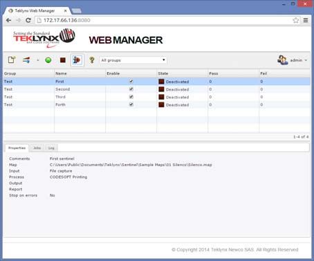
Table of Contents

About this manual . . . . . . . . . . . . . . . . . . . . . . . . . . . . . . . . . . . . . . . . . . 2 - 5
     Documents supplied . . . . . . . . . . . . . . . . . . . . . . . . . . . . . . . . . . . . . . . 2 - 5
     Typographical conventions . . . . . . . . . . . . . . . . . . . . . . . . . . . . . . . . . . 2 - 5
Installation . . . . . . . . . . . . . . . . . . . . . . . . . . . . . . . . . . . . . . . . . . . . . . . . 1 - 1
System Requirements . . . . . . . . . . . . . . . . . . . . . . . . . . . . . . . . . . . . . . . 1 - 2
   Server Requirements . . . . . . . . . . . . . . . . . . . . . . . . . . . . . . . . . . . . . . 1 - 2
   Workstation Requirements . . . . . . . . . . . . . . . . . . . . . . . . . . . . . . . . . . 1 - 3
Software Protection . . . . . . . . . . . . . . . . . . . . . . . . . . . . . . . . . . . . . . . . . 1 - 4
   Activating the software key protection . . . . . . . . . . . . . . . . . . . . . . . . . 1 - 4
Server Installation. . . . . . . . . . . . . . . . . . . . . . . . . . . . . . . . . . . . . . . . . . . 1 - 8
Design/Workstation Installation . . . . . . . . . . . . . . . . . . . . . . . . . . . . . . . . 1 - 8
Running the Label Print Manager Service . . . . . . . . . . . . . . . . . . . . . . . . 1 - 9
   Setting up a user account . . . . . . . . . . . . . . . . . . . . . . . . . . . . . . . . . . 1 - 10
   Installing/Uninstalling the Label Print Manager Service . . . . . . . . . . . 1 - 11
Introduction . . . . . . . . . . . . . . . . . . . . . . . . . . . . . . . . . . . . . . . . . . . . . . 2 - 13
Definition of terms . . . . . . . . . . . . . . . . . . . . . . . . . . . . . . . . . . . . . . . . .         2 - 14
Basic concepts . . . . . . . . . . . . . . . . . . . . . . . . . . . . . . . . . . . . . . . . . . . .        2 - 15
How it works . . . . . . . . . . . . . . . . . . . . . . . . . . . . . . . . . . . . . . . . . . . . . .      2 - 15
The Application Modules . . . . . . . . . . . . . . . . . . . . . . . . . . . . . . . . . . . 3 - 17
The application modules . . . . . . . . . . . . . . . . . . . . . . . . . . . . . . . . . . . .               3 - 18
   Web Manager . . . . . . . . . . . . . . . . . . . . . . . . . . . . . . . . . . . . . . . . . . .          3 - 18
   User Manager . . . . . . . . . . . . . . . . . . . . . . . . . . . . . . . . . . . . . . . . . . .         3 - 18
   Kernel . . . . . . . . . . . . . . . . . . . . . . . . . . . . . . . . . . . . . . . . . . . . . . . . .   3 - 18
   Sentinel Manager . . . . . . . . . . . . . . . . . . . . . . . . . . . . . . . . . . . . . . . .           3 - 18
   Mapper . . . . . . . . . . . . . . . . . . . . . . . . . . . . . . . . . . . . . . . . . . . . . . . .     3 - 18
   Query Manager. . . . . . . . . . . . . . . . . . . . . . . . . . . . . . . . . . . . . . . . . .           3 - 19
The major steps from creating to running the sentinels . . . . . . . . . . . . .                              3 - 19
   On your workstation . . . . . . . . . . . . . . . . . . . . . . . . . . . . . . . . . . . . . .            3 - 19
   On the server . . . . . . . . . . . . . . . . . . . . . . . . . . . . . . . . . . . . . . . . . . .        3 - 19
User Manager . . . . . . . . . . . . . . . . . . . . . . . . . . . . . . . . . . . . . . . . . . . . . 4 - 21
Setting Permissions . . . . . . . . . . . . . . . . . . . . . . . . . . . . . . . . . . . . . . . .           4 - 22
Launching the User Manager . . . . . . . . . . . . . . . . . . . . . . . . . . . . . . . . .                  4 - 22
Adding new users . . . . . . . . . . . . . . . . . . . . . . . . . . . . . . . . . . . . . . . . . .          4 - 22
Defining or changing user rights. . . . . . . . . . . . . . . . . . . . . . . . . . . . . . .                 4 - 23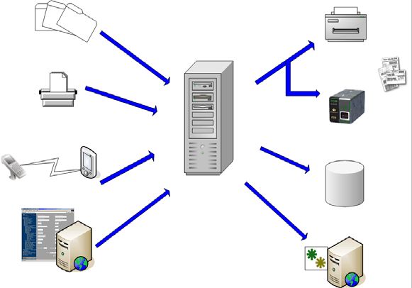
Administrator’s Guide

Changing a password. . . . . . . . . . . . . . . . . . . . . . . . . . . . . . . . . . . . . . .           4 - 24
Web Manager . . . . . . . . . . . . . . . . . . . . . . . . . . . . . . . . . . . . . . . . . . . . . 5 - 25
User Interface . . . . . . . . . . . . . . . . . . . . . . . . . . . . . . . . . . . . . . . . . . . . .   5 - 26
Permissions . . . . . . . . . . . . . . . . . . . . . . . . . . . . . . . . . . . . . . . . . . . . . .    5 - 28
Using the Web Manager. . . . . . . . . . . . . . . . . . . . . . . . . . . . . . . . . . . . .             5 - 29
   Creating or Modifying an Existing Sentinel . . . . . . . . . . . . . . . . . . . . .                    5 - 29
   Sending Out the Sentinels . . . . . . . . . . . . . . . . . . . . . . . . . . . . . . . . .             5 - 30
Sentinels . . . . . . . . . . . . . . . . . . . . . . . . . . . . . . . . . . . . . . . . . . . . . . . . 6 - 33
What are sentinels and how do they work? . . . . . . . . . . . . . . . . . . . . . .                       6 - 34
How do sentinels work? . . . . . . . . . . . . . . . . . . . . . . . . . . . . . . . . . . . . .           6 - 35
Sentinel Manager . . . . . . . . . . . . . . . . . . . . . . . . . . . . . . . . . . . . . . . . . . 7 - 37
Launching the program . . . . . . . . . . . . . . . . . . . . . . . . . . . . . . . . . . . . .            7 - 39
Description of the main window . . . . . . . . . . . . . . . . . . . . . . . . . . . . . . .               7 - 39
    Menu Bar . . . . . . . . . . . . . . . . . . . . . . . . . . . . . . . . . . . . . . . . . . . . . .   7 - 40
    Workspace . . . . . . . . . . . . . . . . . . . . . . . . . . . . . . . . . . . . . . . . . . . . .    7 - 40
    The Toolbar . . . . . . . . . . . . . . . . . . . . . . . . . . . . . . . . . . . . . . . . . . . .    7 - 40
    The Sentinel list . . . . . . . . . . . . . . . . . . . . . . . . . . . . . . . . . . . . . . . . .    7 - 40
    Information panel . . . . . . . . . . . . . . . . . . . . . . . . . . . . . . . . . . . . . . . .      7 - 40
Interface settings . . . . . . . . . . . . . . . . . . . . . . . . . . . . . . . . . . . . . . . . . .     7 - 41
    Changing display options . . . . . . . . . . . . . . . . . . . . . . . . . . . . . . . . . .           7 - 41
    Changing the interface language . . . . . . . . . . . . . . . . . . . . . . . . . . . .                7 - 41
    Adjusting column width . . . . . . . . . . . . . . . . . . . . . . . . . . . . . . . . . . . .         7 - 41
    Adding a sentinel . . . . . . . . . . . . . . . . . . . . . . . . . . . . . . . . . . . . . . . .      7 - 41
    Defining the properties of a sentinel . . . . . . . . . . . . . . . . . . . . . . . . . .              7 - 41
    Displaying a specific group . . . . . . . . . . . . . . . . . . . . . . . . . . . . . . . . .          7 - 42
    Modifying the display order. . . . . . . . . . . . . . . . . . . . . . . . . . . . . . . . .           7 - 42
    Displaying sentinel properties. . . . . . . . . . . . . . . . . . . . . . . . . . . . . . .            7 - 42
Managing sentinels . . . . . . . . . . . . . . . . . . . . . . . . . . . . . . . . . . . . . . . .         7 - 42
    Duplicating a sentinel . . . . . . . . . . . . . . . . . . . . . . . . . . . . . . . . . . . . .       7 - 43
    Deleting a sentinel . . . . . . . . . . . . . . . . . . . . . . . . . . . . . . . . . . . . . . .      7 - 43
    Activating one or more sentinels. . . . . . . . . . . . . . . . . . . . . . . . . . . . .              7 - 43
    Deactivating one or more sentinels . . . . . . . . . . . . . . . . . . . . . . . . . .                 7 - 43
Sentinel status . . . . . . . . . . . . . . . . . . . . . . . . . . . . . . . . . . . . . . . . . . . .    7 - 44
    Task management . . . . . . . . . . . . . . . . . . . . . . . . . . . . . . . . . . . . . . .          7 - 44
    Viewing current tasks . . . . . . . . . . . . . . . . . . . . . . . . . . . . . . . . . . . . .        7 - 45
Error Management . . . . . . . . . . . . . . . . . . . . . . . . . . . . . . . . . . . . . . . . .         7 - 45
    Structure of the error logfile . . . . . . . . . . . . . . . . . . . . . . . . . . . . . . . .         7 - 45
    Error messages . . . . . . . . . . . . . . . . . . . . . . . . . . . . . . . . . . . . . . . . .       7 - 45
    Deleting an error logfile. . . . . . . . . . . . . . . . . . . . . . . . . . . . . . . . . . . .       7 - 46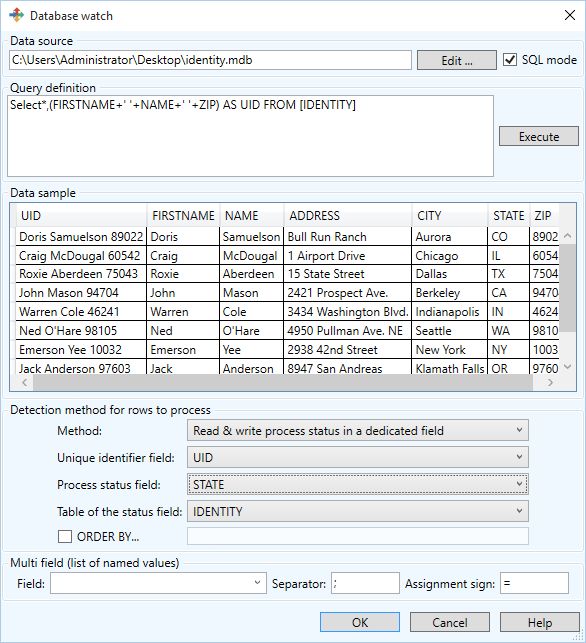
Plug-ins . . . . . . . . . . . . . . . . . . . . . . . . . . . . . . . . . . . . . . . . . . . . . . . . . A - 47
Input plug-ins . . . . . . . . . . . . . . . . . . . . . . . . . . . . . . . . . . . . . . . . . . . . .      A - 48
   File capture . . . . . . . . . . . . . . . . . . . . . . . . . . . . . . . . . . . . . . . . . . . . .     A - 48
   TCP/IP port listening. . . . . . . . . . . . . . . . . . . . . . . . . . . . . . . . . . . . . .           A - 50
   Print capture . . . . . . . . . . . . . . . . . . . . . . . . . . . . . . . . . . . . . . . . . . . .      A - 55
   Web Server. . . . . . . . . . . . . . . . . . . . . . . . . . . . . . . . . . . . . . . . . . . . .        A - 57
   Records capture . . . . . . . . . . . . . . . . . . . . . . . . . . . . . . . . . . . . . . . . .          A - 60
Process plug-ins . . . . . . . . . . . . . . . . . . . . . . . . . . . . . . . . . . . . . . . . . . .        A - 71
   Label Printing . . . . . . . . . . . . . . . . . . . . . . . . . . . . . . . . . . . . . . . . . . .       A - 75
   Database . . . . . . . . . . . . . . . . . . . . . . . . . . . . . . . . . . . . . . . . . . . . . .       A - 78
   Web Service Client . . . . . . . . . . . . . . . . . . . . . . . . . . . . . . . . . . . . . . .           A - 79
Output plug-ins . . . . . . . . . . . . . . . . . . . . . . . . . . . . . . . . . . . . . . . . . . . .       A - 80
   Transfer plug-in. . . . . . . . . . . . . . . . . . . . . . . . . . . . . . . . . . . . . . . . . .        A - 80
Report plug-ins . . . . . . . . . . . . . . . . . . . . . . . . . . . . . . . . . . . . . . . . . . . .       A - 82
   Log file . . . . . . . . . . . . . . . . . . . . . . . . . . . . . . . . . . . . . . . . . . . . . . . .   A - 82
   E-mail . . . . . . . . . . . . . . . . . . . . . . . . . . . . . . . . . . . . . . . . . . . . . . . . .   A - 83
   TCP/IP port listening. . . . . . . . . . . . . . . . . . . . . . . . . . . . . . . . . . . . . .           A - 84
About this manual

Documents       Complete documentation is provided to help you make optimum
supplied        use of the full range of resources offered by your software.

                The Online Help provides instant access to context-sensitive
                help.

                The Administrator’s Guide covers the basic concepts to ensure
                you to get the very most from the software. It is designed to
                provide effective help for administrators, both first-time and
                experienced users.

                The User Guide provides an introduction to using the
                application. It is designed to get you off to a quick start with the
                software by familiarizing you with the basic concepts before
                looking at some of the more advanced functions.

                The documentation is designed for use in conjunction with the
                integrated online help.

Typographical This manual distinguishes between different types of
conventions   information using the following conventions:

                   • Terms taken from the interface itself, such as commands,
                     appear in bold.
                   • Keys appear in small caps. For example: ”Press the SHIFT
                     key.”
                   • Numbered lists mean there is a procedure to follow.
Administrator’s Guide
• When the conjunction -or- appears next to a paragraph,
it means there is the choice of another procedure for
carrying out a given task.
• When a menu command contains submenus, the menu
name followed by the command to select appear in
bold. Thus, ”Go to File > Open” means choose the File
menu then the Open command.
This symbol highlights warnings and other import-
ant information on how a particular command or
procedure works.
Following this symbol you will find hints and tips for
optimizing tasks, speeding up commands, and so
on.CHAPTER 1
Installation
This chapter covers the following topics:
System Requirements
Server Requirements
Workstation Requirements
Software Protection Key
Server Installation
Design/Workstation Installation
Running the Label Print Manager Service
Setting up a User Account
Installing and Uninstalling the Service
Design/Workstation InstallationChapter 1 - 2 Administrator’s Guide
System Requirements
When installing this application, you will install two separate
components of the program – the Server component and the
Design/Workstation component.
Server The Server installation allows you to install the following
Requirements components on your server: the Kernel, the label print
engine, the sentinel manager and the User Manager.
The following requirements must be met to ensure
successful installation:
• OPERATING SYSTEM
Windows® 7 SP1 x86/x64
Windows® 8 x86/x64
Windows® 8.1 x86/x64
Windows® 10 x86/x64
Windows® Server 2008 R2 SP1
Windows® Server 2012, 2012 R2
Windows® Server 2016
Windows® Server 2019
• VIRTUAL MACHINE PLATFORMS
Requires VM license
• MEMORY
4GB or more RAM (8GB recommended - depending on
OS and usage)
• HARD DISK SPACE
A hard drive with at least 10 GB free disk space
(depending on the installation options).
• DISPLAY
Video card: Windows display adapter capable of
1024x768 with True Color capabilities and DirectX® 9
(DirectX 11 compliant card recommended) .
• SUPPORTING SOFTWARE
Microsoft .NET Framework 4.6.1 (provided with the
installation)
Any pdf reader (Adobe Acrobat Reader is available
with the installation)
• ADDITIONAL REQUIREMENTS
Installation requires full Administrator privileges.Installation Chapter 1 - 3
Note
The release note contains the latest information on
the software. This information supersedes the
information contained in this manual.
If you want to create labels on the workstation, you
will have to purchase a separate license for the
label designer to work with this software.
Workstation The Design/Workstation installation allows you to install the
Requirements Mapper module, the Label designer and the Query Manager
on a workstation.
The following minimum requirements must be met to ensure
successful installation.
• OPERATING SYSTEM
Windows® 7 SP1 x86/x64
Windows® 8 x86/x64
Windows® 8.1 x86/x64
Windows® 10 x86/x64
Windows® Server 2008 R2 SP1
Windows® Server 2012, 2012 R2
Windows® Server 2016
Windows® Server 2019
• MEMORY
2GB or more RAM (4GB recommended - depending on
OS and usage)
• HARD DISK SPACE
A hard drive with at least 1.5 GB free disk space
(depending on the installation options).
• DISPLAY
Video card: Windows display adapter capable of
1024x768 with True Color capabilities and DirectX® 9
(DirectX 11 compliant card recommended) .
• ADDITIONAL REQUIREMENTSChapter 1 - 4 Administrator’s Guide
Installation requires full Administrator privileges.
A label designer license (software or dongle) if you
intend to create labels on this workstation
Software Protection
Your software is protected using a software key (en
electronic code) or a hardware key (a dongle).
The dongle is a small electronic device that you plug into
your PC’s parallel or USB port before launching the
software.
The software key is an electronic code that is requested by
the Activation Wizard when you launch the software for the
first time or as long as you have not activated the software.
You must first install the software and then activate or
connect the protection key to your computer.
Activating the Once you have installed the labeling software, the
software key Activation Wizard will be launched, taking you step-by-
protection step through the software key protection process.
To activate the software key
In the Activation Wizard, select Activate.
There are up to four possible activation methods: Online
activation, Using a USB key, Using a smartphone and
Using our website.
Note
If you have an Internet connection on the computer
where the software is installed, online activation is
automatically selected.
Online activation
Some enterprise networks are protected by a proxy server.
In this case, there is a Settings button to setup your proxyInstallation Chapter 1 - 5
settings to connect to the Internet.
1 Enter the Serial number and the password provided
with the product and click Next.
2 Depending on your connectivity, Connection Test step is
displayed. This allows you to setup your connection.
Click Next.
3 Enter or edit your information in the User Registration
form. Click Next.
4 Click Finish.
Note
If you do not have an Internet connection on the
computer where the software is installed but you
have access to another computer with an Internet
connection, you can activate the product using a
USB key.
Using a USB key
1 Enter the Serial number and the password provided with
the product and click Next.
2 Select Using a USB key.
3 Select the media to be used for activation (USB key or
external hard disk or network drives) and click Next. Files
for activation will be copied onto the selected media.
4 USB devices only: Unplug the removable media and plug
it into the computer connected to Internet.
5 On the computer connected to the Internet, double-click
USBWizard.exe (which can be found on the root of the
media). This will start the Activation wizard.
6 Select the license(s) to activate and click Next.
7 Enter or edit your information in the User Registration
form. Click Next.Chapter 1 - 6 Administrator’s Guide
A message will inform you that the activation information
for the selected license(s) has been successfully
retrieved.
8 USB devices only: Unplug the removable media from
this computer and plug it back into the computer where
the software is installed.
9 On the computer where the software is installed, double-
click USBWizard.exe again (the file can be found on the
root of the media).
The wizard will display the license that can be activated
on the computer where the software is installed.
10 Click Next.
11 Click Finish.
If any problems were encountered, a message will inform
you that the activation has failed and an error will be
displayed.
Note
If you do not have access to a computer with an
Internet connection, you can activate the product
using a smartphone.
Using a smartphone
A barcode scanner application is required to read the
barcode which allows you to activate your software using a
smartphone. You can download this from your application
store / market. This activation mode uses an Internet
connection on your smartphone.
1 Enter the Serial number and Password provided with
the software and click Next.
2 Select Using a smartphone.
3 Input your information in the User Registration form. ClickInstallation Chapter 1 - 7
on Next.
4 A barcode appears. Move the cursor over the barcode to
zoom in.
5 Open your barcode scanner application on
your smartphone.
6 Scan the barcode with your smartphone.
7 Click Continue or open the browser on the phone.
8 The Software Activation website is displayed. This allows
you to register and activate your software. All fields must
be filled in.
9 Click Submit.
The Validation code and Installation code are
displayed at the bottom of the Software Activation
website page. Please scroll down if necessary.
10 Enter the Validation code and Installation code in the
wizard (using uppercase characters).
11 Click Next.
12 Click Finish.
Using our website
1 Enter the Serial number and Password provided with
the software and click Next.
2 Select Using our website.
3 The link provided on this screen (http://www.teklynx.com/
nsp/) can be reached from a different computer with
Internet access. You or someone else with an Internet
connection can connect to our website to complete the
activation. The Serial Number and Password (provided
with the product) and the User Code (displayed in the
wizard) will be required in order to use this service.Chapter 1 - 8 Administrator’s Guide
4 Enter the license user's information in the User
Registration form displayed on our website. Click Next.
5 Click Submit.
6 The Validation code and Installation code are
displayed on our website. Enter these in the wizard
(using uppercase characters) and click Next.
7 Click Finish.
Server Installation
Server installation allows you to install on your server the
various modules used to build an automatic data exchange
solution between your applications and devices and our
labelling products.
Step 1 Place the DVD in your server’s DVD drive.
Step 2 The installation program should launch
automatically.
If it does not, go to Windows explorer and expand the
letter of the DVD drive. Double click CDSETUP.EXE (for
example, D:\cdsetup.exe).
Step 3 In the tree structure containing the various
installation options, select the server option of the
product you’ve purchased.
Step 4 Follow the on-screen instructions to complete the
installation process.
Design/Workstation Installation
Design/workstation installation installs the Mapper module,
which is used for defining how data exchange will be done
between your application and the Label Print server. In the
Design/Workstation installation of the product you haveInstallation Chapter 1 - 9
purchased, the Query Manager application will also be
available for installation. This installation allows you to set
up queries over a database system that can be executed by
the sentinel server during a data exchange between your
data files and your labeling software.
Step 1 Place the DVD in your workstation’s DVD drive.
Step 2 The installation program should launch
automatically.
If it does not, go to Windows explorer and expand the
letter of the DVD drive. Double click (e.g. D:\start.bat).
Step 3 In the tree structure containing the various
installation options, select Design/workstation and then
the required components.
Step 4 Follow the on-screen instructions to complete the
installation process.
If you want to design a label and to use the label
design option available with the Mapper, you will
have to purchase a separate license for the label
designer to work with this software.
Running the Label Print Manager Service
The application runs as a service on the host workstation.
This means it will launch automatically when the workstation
is started.
Step 1 To define the startup options for the Label Print
Manager Service, open Services control panel and
select Label Print Manager.
Step 2 Select a start method.
Choose either:Chapter 1 - 10 Administrator’s Guide
Automatic: The service launches when the workstation
is started.
Manual: The service must be activated manually. You
will therefore need to open a Windows work session and
then launch the service in Control panel Services. Select
Label Print Manager from the list of services and then
click Start.
The above start methods launch the service and
the sentinels at the same time. All available
sentinels are thus launched when the service is
started.
Whatever the start method is, you can control the service
activity by launching the Kernel from the application
programs group.
If the service is stopped, a start request is sent to the
system. When the service is started, the application
management icon displays in the system tray. Using this
icon, you can start or stop the service and the different
application modules.
Unlike the start method using the Windows Control
panel services, the start method from the Kernel
does not launch sentinels (which would instead be
launched from the Manager).
Setting up a user The application must be able to access shared network
account folders and print on network printers. You must therefore
select a user account to which these rights have been
assigned.
Step 1 Select a user account, then enter the password.Installation Chapter 1 - 11
The selected account must be declared in the
local administrator group of the workstation.
To view sentinel status while the service is
running, simply open a work session and then
launch the application via the program group
defined during installation. The default name of the
group is the same as that of the application.
Installing/ Once the application is installed, you can always uninstall
Uninstalling the the Label Print Manager service and reinstall it later.
Label Print
Manager Service
To install the Label Print Manager service,
select Start > Run
C:\Windows\Microsoft.NET\Framework\v4.0.30319\
installutil.exe" [name of application installation folder] \
TKXKernel.exe"
To uninstall the Label Print Manager service,
select Start > Run
C:\Windows\Microsoft.NET\Framework\v4.0.30319\
installutil.exe "[name of application installation folder] \
TKXKernel.exe" /uCHAPTER 2
Introduction
This chapter covers the following topics:
Definition of Terms
Basic Concepts
How it WorksChapter 2 - 14 Administrator’s Guide
This application is a server application dedicated to the data
exchange between your application and our products.
It allows you to automatically print barcode labels created
with your labeling software by simply exchanging
information between your ERP/WMS system and the
sentinels server.
Definition of terms
The application involves a number of specific concepts
which are explained below.
Sentinels server: PC running supported Microsoft
Windows platform on which the application is installed.
Input data: The data generated by your system. They are
received by the sentinels server via a communication
channel.
Bearer channel: Once launched, each sentinel “listens” to
a specific bearer channel.
Sentinel printer: The printer created by the application on
the print server which users can then designate as the
output printer in their applications.
Sentinel: The procedure used for analyzing and processing
data generated by your application.
Mapfile: Describes the method the sentinel will use for
analyzing input data.
Plug-in: The process module executes a specific task
during a sentinel process.
There are four types of plug-ins:
• The Input plug-in listens to a data bearer channel
supplying a sentinel.
• The Process plug-in processes information retrieved
from input data.
• The Report plug-in informs users and updates a reportIntroduction Chapter 2 - 15
about sentinel process.
• The Output plug-in backs up or transmits input data to
a file
Plug-ins list available in your application depends
on the product used.
Basic concepts
The application monitors data communication channels
connected with your system. As soon as a channel receives
data, the application analyzes the incoming data and
processes them through one or more process plug-ins. The
communication channel has to be chosen according to your
application and the input plug-in you have at your disposal.
How it works
The application runs as a Windows background task. This
application is considered a service by the system and can
thus be launched with the system. Sentinels are used to
define analysis and printing tasks. Once launched each
sentinel monitors the bearer channel for which it has been
configured. When data coming from your system are
received on the bearer channel, the analysis and process
activity begin.
Input data is filtered by the map file of the sentinel. As for
each printing request, input data information is sent to the
different process plug-ins configured for the sentinel.
At the end of the process, input data is sent to the output
plug-in in order to be transferred or saved.
During each step of the process and after sentinel
validation, information concerning the sentinel process is
sent to the report plug-in.Chapter 2 - 16 Administrator’s Guide
File
Laser
Capture
Printer
Print
Capture Thermal
Printer
TCP/IP
Server
Database
Web
Service
HTTP
Figure 1: Input and Process Plug-in FlowCHAPTER 3
The Application Modules
This chapter covers the following topics:
The Application Modules
Web Manager
User Manager
The Kernel
Sentinel Manager
Mapper
Query Manager
Plug-ins
The major steps from creating to running the sentinels.
On your Workstation
On the ServerChapter 3 - 18 Administrator’s Guide
The application modules
Web Manager The Web Manager acts as an interface to the sentinels
server over the internet/intranet. It allows the user to interact
with any sentinels server, regardless of its location, via their
Internet browser by typing in the web application’s address
in the browser’s address line.
User Manager The User Manager secures the internet connections to the
sentinels server, by allowing an administrator to set
permissions for application users.
Kernel The Kernel is the core application that manages all other
tasks, including launching sentinels and monitoring sentinel
activity. If the Kernel is closed, all sentinels will be disabled.
The Kernel operates as a background task and can be
configured to launch automatically when your workstation is
started up. It is therefore not necessary to open a Windows
work session for the application to run.
Once launched from the application program group, the
Kernel module appears as an icon on the Windows taskbar.
You can access Sentinel Manager via the Kernel menu.
Step 1 Right-click on the Kernel icon
Step 2 Choose Sentinel Manager in the menu.
Sentinel Manager Sentinel Manager is launched via the Kernel menu. It allows
you to create, configure, and manage the sentinels that will
analyze your input data, to view sentinel status, activate or
deactivate individual sentinels and display the error logfiles.
Mapper The Mapper allows you to create and configure the mapfiles
which will analyze your input data. A mapfile describes the
structure of the input data for analysis and assigns the
mapped data to the corresponding variables in the initial
document. Mapper is accessed via the application program
group or Sentinel Manager.The Application Modules Chapter 3 - 19
Mapper features an integrated wizard to guide you through
the process of creating and configuring mapfiles. See the
User Guide for a full description of the module and examples
of how to create mapfiles.
Query Manager This application module lets you define queries over
different database systems and lets you group them into
tasks that can later be invoked by a sentinel through the use
of the database process plug-in.
The major steps from creating to running the
sentinels
Here is a general overview of the main steps to take in order
to configure a sentinel that will receive text files into a
specific folder and will print the corresponding barcode
label.
On your Use the Mapper module to:
workstation
• Define the structure of the files that will be used for label
printing (known as “mapfiles”).
• Design the labels directly in your labeling software.
• Test the map.
On the server Use Sentinel Manager to:
• Create sentinels that will analyze your input data from
the text files.
• Define their properties and the properties of the
plug-ins associated with them.
• Enable sentinels for starting.
• Enable individual sentinels.
• Launch printing.
• Monitor printing.Chapter 3 - 20 Administrator’s Guide
-or-
Use the Web Manager, via the web, to create, define,
enable and launch sentinels. The Web Manager acts as an
online Sentinel Manager.CHAPTER 4
User Manager
This chapter covers the following topics:
Launching the User Manager
Adding New Users
Defining or Changing User Rights
Changing a PasswordChapter 4 - 22 Administrator’s Guide
Setting Permissions
In order to secure the internet connections to the sentinels
server, the User Manager will allow an administrator to set
permissions for application users. The different types of
permissions include:
• Administrate: Allows the user to launch the Security
Management module and change the rights of other
users.
• Manage: Allows the user to add, remove or configure
sentinels as well as enable/disable sentinels.
• Operate: Allows users to start/stop sentinels.
• Control: Allows the user to view sentinel activity via the
Web Manager without any right to alter the settings or
activity of the sentinels in any way.
Launching the User Manager
The User Manager can be launched from Sentinel Manager
Tools menu.
Figure 2: User Manager window
Adding new users
Once you’ve launched the User Manager:User Manager Chapter 4 - 23
Step 1 Go to User and select Add.
A box will pop-up prompting you to enter a user name,
user role and password.
Figure 3: Create User window
Step 2 Click OK.
You will see that the user has been added to the list.
Defining or changing user rights
Determine the user whose rights you want to set or change.
Step 1 Go to User.
Step 2 Select the highest level or rights you want to
assign the user.
If like to give a user the ability to start/stop sentinels, select
Operate from the list of available permissions. You will
notice that Yes appears for each right given to the user. In
this case, you would see Yes under Operate and Control,
but not under Manage and Administrate.Chapter 4 - 24 Administrator’s Guide
Changing a password
The User Manager also allows you to change the password
assigned to users.
Step 1 Go to User.
Step 2 Select Change password.
Step 3 Enter the old password.
Step 4 Enter a new password.CHAPTER 5
Web Manager
This chapter covers the following topics:
User Interface
Permissions
Using the Web Manager
Creating or Modifying an Existing Sentinel
Sending Out the SentinelsChapter 5 - 26 Administrator’s Guide
The Web Manager is the user interface for the sentinels
server. It can be accessed by any user, from any browser,
anywhere in the world, as long as that user has been given
permission, a user name, and a password by the
administrator.
Note
The installation activates the Internet Information
Services (IIS) feature if it is not already activated and
it creates the “Web Manager” web application in a
dedicated application pool.
The Web Manager can be installed on a different server
from the one sentinels server runs on. Installing them on
separate servers ensures that:
• The deployment and maintenance of the Web Manager
application is easier and runs more smoothly since a
single web server can administrate multiple sentinels
server on the network.
• They are each running at full power by giving the Web
Manager and the sentinels server their own server.
Depending on the number of opened sessions, the
Web Manager can consume a lot of processor time
which may hinder the power of sentinels server.
• Web Manager host PC must have access to the server
where SENTINEL Service is running and to the port
4504.
User Interface
Typing in the Web Manager’s URL in the browser will
display the Data Exchange Server’s login page.
Example: http://192.0.0.1:8090
Note
By default, Web Manager installation proposes to
use “All unassigned” address. It means that all free
IP addresses of the server that are not specifically
assigned to another website hosted on the server will
lead to the Web Manager.Web Manager Chapter 5 - 27
Figure 4: Web Manager Login screen
This page is the gateway to the Sentinel Control and
Configuration page.
Step 1 Enter a valid user name and password (these
have been configured and given to you by an
administrator).
Step 2 Select the name of the sentinels server you want
to work with.
Step 3 Click Connect.
The selection of the server is done from a combo box. This
combo box is linked to a file that the administrator has
configured which lists the available sentinels server names
and the associated TCP/IP port to be used (if no port is
specified, a default port will be used instead).
If your connection is successful, a page listing all the
sentinels defined on the sentinels server will be displayed. If
not, please try again, or contact your administrator to verify
that your user name and password are correct.Chapter 5 - 28 Administrator’s Guide
Figure 5: Sentinel list window
Permissions
The administrator can set up your account to give you some
or all of the possible permissions.
Depending on the permissions you have been given, your
account may allow you to:
• Create a new sentinel
• Delete one or more sentinels
• Edit or modify the settings of a particular sentinel
• Enable one or more sentinels
• Disable one or more sentinels
• Start one or more sentinels
• Stop one or more sentinels
• Refresh the Web Manager
The following icons are to be used for the above mentioned
functions:Web Manager Chapter 5 - 29
Create a new sentinel
Edit or modify the settings of a particular sentinel
Start one or more sentinels
Stop one or more sentinels
Using the Web Manager
Once the user has successfully logged in, a list of available
sentinels will be displayed. Just like in the Sentinel Manager,
the group name, the sentinel name, its state and whether
the sentinel has been enabled will be displayed on the
screen.
One or multiple sentinels can be selected by clicking in the
check box - a check mark will appear to show that it has
been selected and the selected sentinel(s) will change to the
color orange. Clicking in a group box will automatically
select all the sentinels belonging to that group. Disabling a
sentinel will change the ‘enable’ box color to red. Starting
the sentinel will change the ‘state’ box to green. In an
unselected, enabled and stopped state, the sentinel
remains in the default color - white.
The icons below the list can be used to perform a number of
tasks as long as the user’s account has the permission to do
so.
Creating or Clicking the Create new sentinel icon or selecting a
Modifying an
Existing Sentinel sentinel and clicking the Edit/Modify sentinel icon
will bring up the Sentinel Configuration screen. Here, the
user can select the sentinel’s input/output/process/report
plug-ins.Chapter 5 - 30 Administrator’s Guide
Figure 6: Plug-in settings screen
Only one input plug-in can be selected for each sentinel,
however, you can select as many output, process or report
plug-ins as you would like.
For more information on the different plug-ins and
their settings, please see Appendix A - Plug-ins.
Sending Out the To send out the sentinels, you must:
Sentinels
Step 1 Select the sentinel(s) you want to activate by
clicking in the appropriate check box.
Step 2 Click to start the selected sentinel(s). The
screen should automatically refresh to show the state of
the sentinel(s) as “running.”Web Manager Chapter 5 - 31
Clicking will stop the selected sentinel(s).
Stopping sentinels may take a few seconds. The
more sentinels you stop at one time, the longer it
may take.CHAPTER 6
Sentinels
This chapter covers the following topics:
What Are Sentinels?
How Do Sentinels Work?Chapter 6 - 34 Administrator’s Guide
What are sentinels and how do they work?
A sentinel is simply a group of settings the application uses
to intercept and process the information coming from your
application and devices.
Once activated, each sentinel acts on your system as an
analyzing and processing service giving you the ability to
exchange data between your application and TEKLYNX
products in order to build a complete automatic ID solution.
Each sentinel must specify:
• A bearer channel on which your printing requests will
be received.
• A method for data analysis given by the map file
selection associated with a sentinel.
• One or several types of processes to be implemented
for each information block identified in the input data
according to the sentinel map file.
• One or several types of logs to be generated when a
specific event is detected during analysis or during
input data process.
• One or several types of backup input data once they
have been treated.
A sentinel must belong to a group. Each group can contain
as many sentinels as your organization requires. The
organization of sentinels within a given group is just
performed for organizational purposes.
The choice of possibilities for communication
channels, type of process, type of log generated,
and type of backup will vary depending on the
labeling software version you are using and the
plug-ins available for that product version.Sentinels Chapter 6 - 35
How do sentinels work?
After you have selected an input plug-in and one or more
output plug-ins for your sentinel, when the sentinel is
activated, the input plug-in is also activated and it monitors
its bearer channel. When information is received on its
channel, the plug-in sends input data to the core application.
Data are then analyzed according to the map file associated
to the sentinel.
For each information block detected, the core application
sends data to the different plug-ins associated with the
sentinel. Data are treated according to the order sets up in
the sentinel. Once data are treated, the analysis goes on
towards the next blocks. The same process is repeated until
all the data have been processed.
The core application sends data received by the input plug-
in to the different output plug-ins. These plug-ins are
configured to implement the different backup processes.
For each step of the process, the activity parameters of the
sentinel are provided to the selected log plug-ins, by the
core application.
The diagram below shows the workflow.Chapter 6 - 36 Administrator’s Guide
Note
Some sample files for the this applications are
available in the document folder of the application
(C:\Users\Public\Public Documents or C:\Document
And Settings\All Users\Documents)CHAPTER 7
Sentinel Manager
This chapter covers the following topics:
Launching the Program
Description of the Main Window
Menu Bar
Workspace
The Sentinel List
The Toolbar
Selecting a Tool
Information Panel
The Status Bar
Interface Settings
Changing Display Options
Changing the Interface Language
Adjusting Column Width
Adding a Sentinel
Defining the Properties of a Sentinel
Displaying a Specific Group
Modifying the Display Order
Displaying Sentinel Properties
Activating one or more Sentinels
Deactivating one or more Sentinels
Managing Sentinels
Duplicating a Sentinel
Deleting a Sentinel
Activating a Sentinel
Sentinel StatusChapter 7 - 38 Administrator’s Guide
Task Management
Viewing Current Tasks
Cancelling a Task
Error Management
Structure of the Error Logfile
Error Messages
Deleting an Error LogfileSentinel Manager Chapter 7 - 39
Launching the program
Once launched from the application program group, the
Kernel module appears as an icon on the Windows taskbar.
To access Sentinel Manager:
Step 1 Right-click on the Kernel application icon .
Step 2 Choose Sentinel Manager in the menu.
The main Sentinel Manager window appears.
Figure 7: Sentinel Manager window
Description of the main window
This section presents a general overview of the main
elements that make up the interface as they appear in the
main window at the beginning of a work session. The main
window is divided into two areas:
• The sentinel list
• The information panelChapter 7 - 40 Administrator’s Guide
Menu Bar The menu bar comprises four drop-down menus: Sentinel,
View, Tools, and Help.
To access commands using the keyboard, use the
keyboard shortcuts. Press ALT plus the key
corresponding to the letter underlined in the menu
name, then the key corresponding to the letter
underlined in the command name.
Workspace The workspace occupies the central part of the main
window. The list of sentinels is displayed in this area as a
table.
The Toolbar These tools allow you to execute routine tasks more quickly
than using the menus.
To select a tool, click the button corresponding to the tool.
The Sentinel list The sentinel list occupies the central part of the main
window and is displayed as a table.
Information The information panel, located in the lower part of the
panel window, comprises three tabs which display information on
pending tasks and the printing/error logfiles respectively.
You can show or hide the information panel using the
command View Information or the Information tool
button .Sentinel Manager Chapter 7 - 41
You can move the border separating the sentinel
list and the information panel by dragging it with
the cursor.
Interface settings
Changing You can display the interface in English or French. You can
display options also modify column widths and select a display filter.
Changing the Step 1 Choose Tools > Options.
interface Step 2 Select the required language in the language
language zone.
A checkmark shows which language is selected.
Adjusting Place the cursor over the column’s right-hand border in the
column width table header and drag it to the left or right to obtain the
required width.
Adding a sentinel Choose Sentinel > New.
The new sentinel appears in the table. Its status is defined
as ”under construction”.
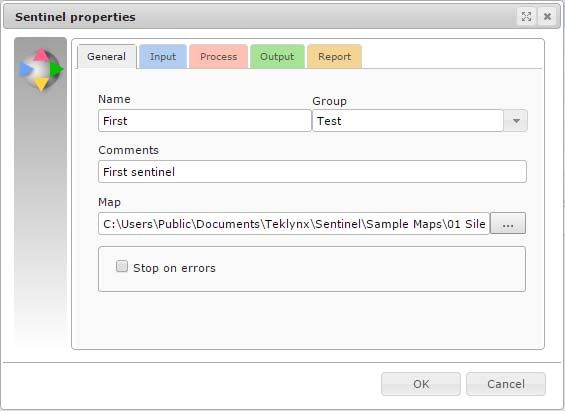
Defining the The General tab allows you to assign a name to the new
properties of a sentinel, add any comments and associate it with a group
sentinel and a map file.
Step 1 Enter a name in the zone Name.
Step 2 In the zone Group, select a group or type a group
name. If needed, type comments.
Step 3 Select the map file defining the structure of your
data file.
Step 4 Select the Stop on errors check box if you want
a sentinel process to be stopped when an error occurs.Chapter 7 - 42 Administrator’s Guide
The others tabs allow you to define which plug-in you want
to run for the Input, the Output, the Process and the Report.
If you want more information about the plug-ins, please refer
to Appendix A: Plug-ins at the end of this manual.
You will also find information about the plug-in selected in
each tab of the Sentinel Properties dialog box.
Displaying a You can display sentinels belonging to a particular group.
specific group
Choose View > Group and then select the required group
of sentinels.
- or -
Select the option directly from the toolbar.
Modifying the Click on the header of the column by which you wish to sort
display order the sentinels.
Displaying You can display the properties of a sentinel.
sentinel
Step 1 Select the sentinel.
properties
Step 2 Choose View Information.
Step 3 Click the Properties tab.
Managing sentinels
Sentinel Manager allows you to carry out a number of
operations, including duplicating an existing sentinel.Sentinel Manager Chapter 7 - 43
Duplicating a Step 1 Select the sentinel.
sentinel
Step 2 Right-click the sentinel.
Step 3 Choose Duplicate in the context menu.
The duplicated sentinel appears in the list with the same
name followed by copy no. x.
Deleting a Sentinel Manager also allows you to delete sentinels.
sentinel
Step 1 Select the sentinel.
Step 2 Right-click the sentinel.
Step 3 Choose Delete in the context menu.
Activating one or In order to activate a sentinel (from the service or from the
more sentinels Sentinel Manager), you must first enable it.
Step 1 Select the required sentinel(s) using the mouse or
the Select all and Invert selection commands.
Step 2 Check or un check the box in the Enable column.
Step 3 Click the button to activate the selection.
- or -
Choose Sentinel > Activate.
Deactivating one Step 1 Select the required sentinel(s) using the mouse or
or more sentinels the Select all and Invert selection commands.
Step 2 Click the button to deactivate the selection.
- or -
Choose Sentinel > Deactivate.Chapter 7 - 44 Administrator’s Guide
Unlike sentinels are activated by the service, all
sentinels launched manually will stop processing
when the application is closed.
Sentinel status
A symbol appears next to each sentinel in the list to indicate
its status.
This symbol indicates the sentinel is deactivated.
This symbol indicates the sentinel is about to begin
analysis.
This symbol indicates the sentinel is under construction.
This symbol indicates the sentinel is activating.
This symbol indicates the sentinel is processing a datafile.
Task The Information panel allows you to monitor the progress of
management current tasks.Sentinel Manager Chapter 7 - 45
Viewing current Activate the Information panel and click the Jobs tab.
tasks
Error Management
When Sentinel Manager detects an error during datafile
analysis, it updates the relevant error logfile located in the
application LOGFILES folder. The filename of the logfile will
be that of the sentinel. The logfile describes the nature of the
error so you can rectify it if necessary.
To view the error logfile for the selected sentinel, display the
Information panel, and then click the Log tab.
The Fail column and the sentinel symbols indicate any
errors encountered during datafile analysis.
To reset failed jobs counter, select a sentinel and then
choose Reset in Sentinel menu.
Structure of the This file allows you to monitor file processing status.
error logfile
Error messages Error messages inform you of the nature and source of any
errors so you can rectify them. Error messages include the
error number, the date and the time, the name of the file
concerned, and the error message.Chapter 7 - 46 Administrator’s Guide
Deleting an error You can delete error logfiles using the Information panel.
logfile
Step 1 Select the sentinel to which the error logfile is
associated.
Step 2 Click on the Information panel Log tab then press
CTRL + DEL.
Deleting an error logfile will permanently remove
the .log file.APPENDIX A
Plug-ins
This appendix covers:
Information about the configuration and selection of the different
plug-ins:
Input
File Capture
TCP/IP Port Listening
Print Capture
Web Server
Records Capture
Process
Label Printing
Database
Web Service Client
Output
Transfer Plug-in
Report
Log File
E-mail
TCP/IP Port Listening
plug-ins list available in your application
depends on the product used.Appendix A - 48 Administrator’s Guide
Input plug-ins
You have five input plug-ins at your disposal:
• File Capture
• TCP/IP Port Listening
• Print Capture
• Web Server
• Records Capture
File capture The File Capture plug-in collects files in a specific folder.
Files are processed in chronological order – the first file to
appear in the folder is the first file processed.
To be analyzed by the sentinel, the file must be
accessible in read/write mode. In addition, the
sentinel must have full control over the data file
before it will proceed with processing (the program
that is creating the data file for sentinel must be
finished writing the file).
From the Input tab of the Sentinel Properties dialog box,
select the Input plug-in and click Settings.
The following dialog box appears:Plug-ins Appendix A - 49
Figure 8 The Print Capture Plug-in window
Step 1 Type or select the file path of the folder to be
watched.
Step 2 Type file name or file extension of the files to be
captured.
You can type several files names separated by a semicolon
or use wildcard characters. Asterisk (*) is used to replace
zero or several characters. Question mark (?) is used to
replace one and only one character in a file name.
Examples
a*.txt All files with extension .txt starting with
a (or A), like AF104.txt or a.txt.
item_n?.* All files named item_n + one
character, whatever the extension,
like item_n3.dat or ITEM_NZ.txt, but
not item_n24.doc
*.txt;*.dat All files with extension txt and datAppendix A - 50 Administrator’s Guide
Step 3 Choose your watch method:
• Wait for file system events: In this mode, the
application is suspended until the system «awakens»
when a file is in the directory. At that time, the file
processing starts.
This method is a good way to limit the resources
needed by the application. However, this method
cannot always be used. Some file systems, such
as shared folders on AS400, are not compatible
with the Windows notification system.
• Check on time interval: The folder is watched at
regular intervals.
TCP/IP port This plug-in is viewed as a Socket server and receives data
listening from a client in a pre-defined format. For more information
about this format, please refer to the example available in
your installation directory. This plug-in can be considered as
an input and/or a report plug-in. It allows client application to
retrieve printing status. This plug-in can support any kind of
platforms.
From the Input tab of the sentinel properties dialog box,
select the input plug-in and click Settings.
The TCP/IP Plug-in window appears:
Figure 9: The TCP/IP Plug-in windowPlug-ins Appendix A - 51
How does this the TCP/IP Plug-in work?
Step 1 The client tries to connect.
Step 2 The server validates the connection.
Step 3 The client sends a data process request.
Step 4 The server sends the events linked to the file
process.
Step 5 The server sends the end of process.
Step 6 The client disconnects or continues sending
information to the sentinel.
If this plug-in is considered as both an input and report plug-
in, events reported by the server to the client will concern
only the client that sent the input.
General message format
A message is sent to exchange information between the
client and the Socket Server. The structure of this message
is defined below.
Message size 4 characters (long)
(including those four
characters)
Command number 4 characters (long)
Parameter 1 4 characters (long)
Parameter 2 4 characters (long)
Job name 260 characters (char [260])
Data varying length
Data format description
Data sent will have the following format:
variable name = CRLF valueAppendix A - 52 Administrator’s Guide
The variable name is the name of a variable on your label or
that of a control variable:
@LABEL_NAME: Used to indicate the label name to be
printed.
@PRINTER_NAME: Used to indicate the target printer.
@LABEL_QUANTITY: Used to indicate the number of
labels to be printed.
If you want to send several process demands during the
same information exchange, data blocks must be separated
by CRLF (ASCII characters 10 and 13).
If there are several blocks of data, blocks are separated by
CRLF:
variable name 1 = value CRLF
variable name 2 = value CRLF
variable name 3 = value CRLF
CRLF
variable name 1 = value CRLF
variable name 2 = value CRLF
variable name 3 = value CRLF
variable name 4 = value CRLF
Messages list
Connection demand
The connection string indicated in the plug-in configuration
is aimed at allowing the client to connect to the server.
Command number 0
Parameter 1 0 (message with Ansi
characters)
1 (message with Unicode
characters)
Parameter 2 Client ID. Optional parameter
used to check information sent
from the server to the client.Plug-ins Appendix A - 53
Name Not used.
Data Connection string.
Job demand
Command number 2
Parameter 1 0 (message with Ansi
characters)
1 (message with UNICODE
characters)
Parameter 2 Not used.
Name Job name.
Data Data to process.
Answer to connection demand
Once the connection demand has been made, the client
must wait for an answer from the server in order to continue.
Job name Client ID.
Command number 1
Parameter 1 0 (OK)
1 (false connection string)
2 (maximum number of clients
reached)
Parameter 2 Not used.
Name Not used.
Data Not used.Appendix A - 54 Administrator’s Guide
Answer to job demand
Command number 3
Parameter 1 0 (OK)
1 (cancelled)
2 (message)
3 (error)
4 (end of process)
Parameter 2 See table below.
Name IP address or client’s PC name
+ client ID (value set during
connection).
Data Text message linked to the
receiving of an error or a
message. The module name or
the name of the plug-in is
defined before this message.
Details about parameter 2
On message 0 (Sentinel stopped: client
reception and disconnected)
according to what has
been selected in the 1 (Data received)
Report plug-in.
2 (Data to be processed)
3 (Data are sent to the output
plug-in)
4 (Free message)
On error reception 3 (Format not supported)
4 (Process error)Plug-ins Appendix A - 55
On end of process Equal to the NewData return
value.
0 (OK)
1 Process canceled.
6 Process error.
7 Output plug-in error.
Communication between the client and the server can either
be done in UNICODE or in ANSI. If client data is sent in
UNICODE, the server will answer in UNICODE. It is the
same process for ANSI.
Server disconnection
The client will be disconnected:
• For the input, if the client tries to send a new process
without having received the end of the process of the
previous demand.
• For the report plug-in only, if the client tries to send
data.
Print capture This plug-in captures spooled tasks on a printer. This printer
is set up during your plug-in configuration. All printed tasks
printed from your system to the printer will be analyzed by
the sentinel once activated.
Printing your document from a Windows application on a
sentinel printer may modify the original document. For
instance empty lines can be removed and tabulation
characters can be replaced by a carriage return line feed
sequence. In order for the map to read the reformatted data
correctly, do the following:
Step 1 Start by making the sentinel printer available for
printing, as it is suspended for the capture by default.
Step 2 Select the FILE port for the output.Appendix A - 56 Administrator’s Guide
Step 3 Print your document on this printer from your
application.
At print time, a dialog box is displayed that lets you
specify the output file name.
Step 4 Use the file that is printed as the work file to define
the Map file.
This method allows for the modifications that could occur
during the printing process.
Step 5 When the map file is done, don't forget to set the
printer back to suspended mode and to select the COM1:
as the output port.
When printing through the TCP/IP protocol, the
original document is not modified through the use
of the driver. In that case it is possible to create
the map file with the original document.
From the Input tab of the sentinel properties dialog box,
select the input plug-in and click Settings.
The Print Capture Plug-in window appears:
Figure 10: Print Capture Plug-in windowPlug-ins Appendix A - 57
Step 6 Select printer spool for input.
Step 7 If you want to add another printer, enter its name
and click Add. The new printer appears in the printer
spool for input list.
Step 8 Click OK to validate.
Web Server
Note
Depending on the product version you have
purchased, this plug-in may not be available.
The Web Server plug-in allows the sentinels server to
receive information from a Web page, previously created
and configured for data collection. It allows the sentinels
server to be connected to any Web Application with a
minimum of integration work on the Web Application itself.
All it would take is for a Submit button on a Web page to be
connected to the server’s URL. This would send all the
information entered in the Web page to be collected and, for
example, inserted into a database or transmitted to a Web
service available on the ERP system to perform a particular
transaction. Since this plug-in acts as an HTTP server, it will
answer an HTTP POST message and will call the assigned
process plug-in to act according to the information. The web
form will need to be customized to link the data collected on
the web page with the information requested by the process
plug-ins used by the sentinel.
Figure 11: Port Configuration windowAppendix A - 58 Administrator’s Guide
In order to customize a Web form, three things must be
done:
Step 1 Create standard input fields, giving them the
name of the variables you want to address from the
fields.
Example:
For more details, please see the HTML sample web
form in the sample program directory.
Step 2 Create three input fields named Group, Sentinel
and Job Name that are used to identify the sentinel which
will receive the data and to provide a name for the job.
Example:
Data will be processed by the sentinel “S01” of the
”Production group”. The Job will be referred to as
“Job2545”.
Step 3 Customize the method and action parameters for
the form so that it could be linked to the sentinels server.
Example:
...
...
...You can also read