Document release 8 - RosettaCNC G-code language - User manual
←
→
Page content transcription
If your browser does not render page correctly, please read the page content below
RosettaCNC G-code language

Document release 8

                                1/75
RosettaCNC G-code language

RosettaCNC G-code language

All rights reserved on this manual. No part of this document can be copied or reproduced in any form without prior written authorisation. RosettaCNC
Motion® does not insure or guarantee its contents and explicitly declines all liability related to the guarantee of its suitability for any purpose. The
information in this document can be changed without notice. RosettaCNC Motion® shall not be held liable for any error or omission in this document.
RosettaCNC Motion® is a registered trademark.

Information

         Document:                                  MDUROSETTACNCSOFTWAREGCODE
         Description:                               RosettaCNC G-code language
         Link:                                      https://wiki.rosettacnc.com/doku.php/software/mdurosettacncsoftwaregcode
         Release documento                          Descrizione                        Note            Data
         01                                         First release                             /           17/01/2018
         02                                         Minor changes                             /           29/01/2019
         03                                         Update for 1.6 version                    /           02/09/2019
         04                                         Update for 1.7 version                    /           29/11/2019
         05                                         Update for 1.7.6 version                  /           04/02/2020
         06                                         Update for 1.7.7 version                  /           04/03/2020
         07                                         Update for 1.8.5 version                  /           01/10/2020
         08                                         Update for 1.9.1 version                  /           23/04/2021

References

This manual explains the control software used by the RosettaCNC software.

All the implementation details refer to the software version: 1.9.1.

The actual control software version can be identified by open the “Help” menu → “About RosettaCNC”.

                                                                          2/75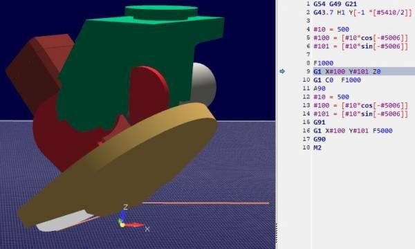
RosettaCNC G-code language

Table of Contents
RosettaCNC G-code language ..................................................................................................... 2
Information .................................................................................................................................... 2
References ..................................................................................................................................... 2
1. Supported G and M Codes ....................................................................................................... 7
  1.1 Supported G Codes ............................................................................................................. 7
  1.2 Supported M Codes .......................................................................................................... 10
  1.3 Other Codes ....................................................................................................................... 12
    “F” for “Feed” .......................................................................................................................... 12
    “S” for “Spindle Speed” ........................................................................................................... 12
    “T” for “Tool” ........................................................................................................................... 12
    Notes ....................................................................................................................................... 12
  1.4 G-Code Comments ............................................................................................................ 12
  1.5 Block delete ....................................................................................................................... 12
  1.6 Go to predefined positions .............................................................................................. 13
    1.6.1 G28 and G28.1 ............................................................................................................... 13
      Examples ............................................................................................................................. 13
    1.6.2 G30 and G30.1 ............................................................................................................... 13
      1.6.2.1 Examples ................................................................................................................. 13
  1.7 G Code Order of Execution .............................................................................................. 15
  1.8 Arcs & Helices .................................................................................................................... 16
    1.8.1 Syntax ............................................................................................................................ 16
    1.8.2 Center Format Arcs ......................................................................................................... 16
      Incremental Arc Distance Mode ........................................................................................... 16
      Absolute Arc Distance Mode ................................................................................................ 17
    1.8.3 Radius Format Arcs ......................................................................................................... 17
    1.8.4 Examples ........................................................................................................................ 17
    1.8.5 Center format arcs incremental mode ............................................................................ 17
    1.8.6 Full circles and helices .................................................................................................... 18
2. G-Code variables ..................................................................................................................... 19
  2.1 System variables description ......................................................................................... 19
  2.2 Named variables ............................................................................................................... 21
    2.2.1 Global and local scopes .................................................................................................. 21
    2.2.2 Indexing support ............................................................................................................. 21
    2.2.3 Pre-defined Named Parameters ...................................................................................... 22
    2.2.4 Examples ........................................................................................................................ 26
  2.3 Position Information ......................................................................................................... 26
  2.4 Vacant or Empty Variables .............................................................................................. 27
  2.5 Local variables .................................................................................................................. 29
3. Macro programming ............................................................................................................... 30
  3.1 Arithmetic Logic & Statements ...................................................................................... 31
    3.1.1 Binary Operators ............................................................................................................ 31
    About equality and floating-point values ................................................................................. 31
    3.1.2 Functions ........................................................................................................................ 31
  3.2 Looping & Branching ........................................................................................................ 32
    3.2.1 Unconditional Branching ................................................................................................. 32
    3.2.2 Conditional Branching .................................................................................................... 32
    3.2.3 IF-THEN Option ............................................................................................................... 32
    Single line syntax .................................................................................................................... 32
    Multi line syntax ...................................................................................................................... 32

                                                                         3/75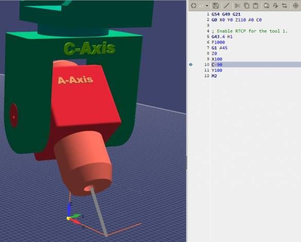
RosettaCNC G-code language

    Multi line syntax with ELIF ....................................................................................................... 32
    3.2.4 While Loop ...................................................................................................................... 32
    3.2.5 About unique IDs ............................................................................................................ 33
    3.2.6 Example .......................................................................................................................... 33
  3.3 Custom Macro calls ........................................................................................................... 35
    3.3.1 Non modal Macro calls .................................................................................................... 35
    3.3.2 Modal Macro calls ........................................................................................................... 35
    Example ................................................................................................................................... 35
    3.3.3 Support for encrypted macro files .................................................................................. 36
  3.4 Subroutines ....................................................................................................................... 38
  3.5 User Tool Change Subprogram ....................................................................................... 39
    Examples ................................................................................................................................. 39
    Manual Tool Change ................................................................................................................ 39
    Automatic Tool Change ........................................................................................................... 39
    Manual Tool Change with tool length compensation ............................................................... 40
Advanced Tips ............................................................................................................................. 42
  Subroutine and Macro call efficiency ................................................................................... 42
4. Cutter compensation ............................................................................................................. 43
  4.1 G41, G42 Cutter Compensation ...................................................................................... 43
    Notes ....................................................................................................................................... 43
  4.2 G41.1, G42.1 Dynamic Cutter Compensation ............................................................... 43
    Notes ....................................................................................................................................... 43
  4.3 Tool compensation entry options ................................................................................... 44
    Common Cutter Radius Compensation Errors ......................................................................... 44
  4.4 Examples ............................................................................................................................ 46
    4.4.1 Easy Lead-in ................................................................................................................... 46
    4.4.2 Auto ................................................................................................................................ 47
5. Motion Control Modes ............................................................................................................ 49
  5.1 Examples ............................................................................................................................ 49
    Exact stop one shot example .................................................................................................. 49
    Path smoothing support .......................................................................................................... 50
6. Canned Cycles ......................................................................................................................... 51
  6.1 List of supported Canned Cycles .................................................................................... 51
  6.2 G73 High Speed Peck Drilling Cycle ............................................................................... 51
  6.3 G80 Cancel motion mode / Canned Cycle Cancel ......................................................... 52
7. Feed Management .................................................................................................................. 53
  7.1 Rotary Axes Indexer option ............................................................................................. 53
  7.2 Rotary Axes Continuous Machining ............................................................................... 53
    Single-axis feedrate moves ..................................................................................................... 53
    Multi-axis feedrate "mixed moves" .......................................................................................... 53
      RosettaCNC "mixed moves feed handling" feature .............................................................. 53
      Standard macro approach .................................................................................................... 54
8. Coordinate Systems ............................................................................................................... 56
  8.1 The 5 Steps G-Code Coordinate Pipeline ...................................................................... 56
    8.1.1 Step 1: Unit Conversion .................................................................................................. 56
    8.1.2 Step 2: Conversion from Relative or Polar to Absolute Coordinates ............................... 56
    8.1.3 Step 3: Offsets: G52, G54 and G92 ................................................................................. 56
      Examples ............................................................................................................................. 57
    8.1.4 Step 4: Scaling and Mirroring: G51 ................................................................................. 57
    8.1.5 Step 5: Rotation: G68 ..................................................................................................... 58

                                                                         4/75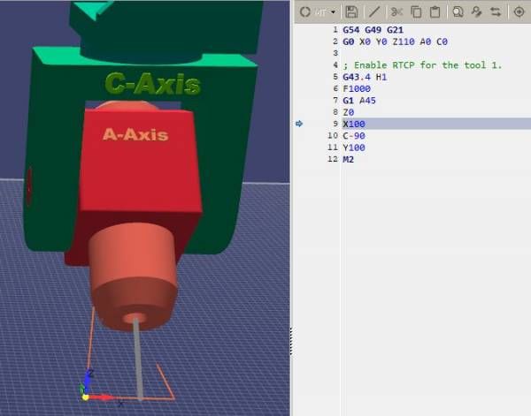
RosettaCNC G-code language

  8.2 Cartesian & Polar Coordinates ....................................................................................... 60
    8.2.1 Use on different planes ................................................................................................... 60
    8.2.2 Standard syntax ............................................................................................................. 60
       Plane independent syntax .................................................................................................... 60
    8.2.3 Examples ........................................................................................................................ 61
    8.2.4 Polar Coordinates standard syntax ................................................................................. 61
    8.2.5 Polar Coordinates complete example ............................................................................. 62
9. Rotary axis options ................................................................................................................ 64
    Example ................................................................................................................................... 64
10. Messages & Media ............................................................................................................... 65
  10.1 Parameters meaning ...................................................................................................... 65
       Notes .................................................................................................................................... 65
  10.2 Supported HTML syntax ................................................................................................ 65
    Bold tag ................................................................................................................................... 66
    Underline tag ........................................................................................................................... 66
    Italic tag .................................................................................................................................. 66
    Strikeout tag ............................................................................................................................ 66
    Line break ................................................................................................................................ 66
    Subscript/Superscript tags ....................................................................................................... 66
    List tags & List items ............................................................................................................... 66
    Text with shadow ..................................................................................................................... 67
    Highlight .................................................................................................................................. 67
    Error marking .......................................................................................................................... 67
  10.3 Supported Not Standard HTML Tags ........................................................................... 67
    Tool Info ................................................................................................................................... 67
  10.4 Examples .......................................................................................................................... 67
    Modal window messages ......................................................................................................... 67
    HUD messages ........................................................................................................................ 68
    Use piece thickness to update WCS offsets ............................................................................. 68
11. Probing ................................................................................................................................... 70
  11.1 Error Cases ...................................................................................................................... 70
    Notes ....................................................................................................................................... 70
    Examples ................................................................................................................................. 70
    Detect piece position ............................................................................................................... 70
12. RTCP ....................................................................................................................................... 72
  12.1 Gcode ................................................................................................................................ 72
    G43.4 ....................................................................................................................................... 72
    G43.7 ....................................................................................................................................... 72
    Example ................................................................................................................................... 73
  12.2 Supported Kinematics .................................................................................................... 73
13. Acknowledgement ................................................................................................................ 75

                                                                         5/75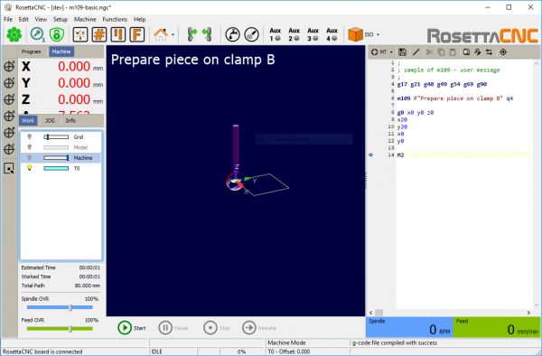
RosettaCNC G-code language

           6/75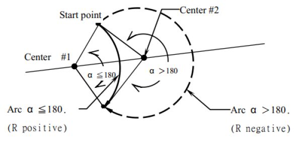
RosettaCNC G-code language
1. Supported G and M Codes
1.1 Supported G Codes
The following table describes supported G-Code commands.
The G-codes and M-codes called in the same line of a G-code file are executed accordingly to G Code Order of Execution.
In the following axes means one or more of X, Y, Z, A, B, C, along with a corresponding floating-point value for a specified axis.
Gcode Parameters Command Description
G0 axes Straight traverse Traverse at maximum velocity.
G1 axes F Straight feed Move at feed rate F.
G2 axes F P IJK or R Clockwise arc feed Arc at feed rate F.
G3 axes F P IJK or R Counterclockwise arc feed Arc at feed rate F.
G4 P Dwell Pause for P seconds.
G9 axes F Exact Stop (non-modal) Move at feed rate F and stop at the end.
Update the tool table adding/updating the tool info with the tool
offset set by the user.
Arguments:
•
P tool id
•
X tool offset X
•
Y tool offset Y
•
Z tool offset Z
•
G10 L1 P axes Set Tool Table Entry D tool diameter
•
Q tool type
•
I tool parameter 1
•
J tool parameter 2
•
K tool parameter 3
•
V tool slot: this should be specified only if the tool is not
already present in the tool table.
Update the tool table adding/updating the tool info with the tool
offset calculated by the G-code interpreter.
•
P tool id
•
X the X position that should be considered 0 when the
tool is loaded and tool offset are used
•
Y the Y position that should be considered 0 when the
tool is loaded and tool offset are used
•
Z the Z position that should be considered 0 when the
tool is loaded and tool offset are used
G10 L10 P axes Set Tool Table, Calculated, Workpiece •
D tool diameter
•
Q tool type
•
I tool parameter 1
•
J tool parameter 2
•
K tool parameter 3
•
V tool slot: this should be specified only if the tool is not
already present in the tool table.
G10 L2 offsets the origin of the coordinate system specified by P
to the value of the axis word.
The offset is from the machine origin established during homing.
G10 L2 P axes Coordinate System Origin Setting The offset value will replace any current offsets in effect for the
coordinate system specified. Axis words not used will not be
changed.
G10 L20 is similar to G10 L2 except that instead of
setting the WCS origin offset, it calculates and sets
G10 L20 P axes Coordinate Origin Setting Calculated
the values that makes the current coordinates
corresponds to the specified arguments.
Set the value of some special
G10 L100 P V
parameters
G15 Switch to Cartesian coordinates
G16 Switch to polar coordinates
7/75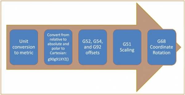
RosettaCNC G-code language

Gcode         Parameters Command                                              Description
G17                                  Select XY arc plane
G18                                  Select XZ arc plane
G19                                  Select YZ arc plane
                                                                              All G-code from this point on will be interpreted in
G20                                  Select inches mode
                                                                              inches
                                                                              All G-code from this point on will be interpreted in
G21                                  Select mm mode
                                                                              millimetres
G28           axes                   Go to G28 position                       Optional axes specify an intermediate point
                                                                              Store the current machine position so that it will be
G28.1                                Set G28 position
                                                                              used by G28
G30           axes                   Go to G30 position                       Optional axes specify an intermediate point
                                                                              Store the current machine position so that it will be
G30.1                                Set G30 position
                                                                              used by G30
G38.2 G38.3
              axes                   Probing
G38.4 G38.5
G40                                  Disable Cutter Compensation
                                     Enable Cutter Compensation left of
G41           DI
                                     programmed path
                                     Enable Dynamic Cutter Compensation
G41.1         DL
                                     left of programmed path
                                     Enable Cutter Compensation right of
G42           DI
                                     programmed path
                                     Enable Dynamic Cutter Compensation
G42.1         DL
                                     right of programmed path
                                                                              H argument is optional, if it is not specified the
G43           H                      Enable Tool Length Compensation
                                                                              current tool is used.
                                                                              Tool compensation is enabled considering the
                                     Enable Dynamic Tool Length
G43.1         XYZ                                                             specified offsets X, Y and Z. The arguments X,Y and
                                     Compensation
                                                                              Z are optional but at least one should be specified.
                                                                              Add the offsets due to the tool specified with the H
G43.2         H                      Apply additional Tool Length Offset
                                                                              argument to the offsets already in use.
                                                                              Enable Rotation tool center point control. (See
G43.4         H                      Enable RTCP feature
                                                                              1. RTCP)
                                     Enable RTCP feature and override tool
G43.7         H
                                     offsets using user defined arguments
                                     Cancel Tool Length Compensation and
G49
                                     disable RTCP feature
G50                                  Disable scaling
G51           X Y Z and I J K or P   Enable scaling
G52           axes                   Local Work Shift                         The values entered are added to all work offsets
G53                                  Select absolute coordinates              Non-Modal: Applies only to current block
                                                                              G54 is typically used as the “normal” coordinate
G54                                  Select coord system 1
                                                                              system and reflects the machine position
G55                                  Select coord system 2
G56                                  Select coord system 3
G57                                  Select coord system 4
G58                                  Select coord system 5
G59                                  Select coord system 6
G59.1                                Select coord system 7
G59.2                                Select coord system 8
G59.3                                Select coord system 9
G61                                  Set exact path mode
G61.1                                Set exact stop mode                      Motion will stop between each G-code block
                                                                              Results in minimum execution time allowing
G64           PQ                     Continuous path mode
                                                                              minimal trajectory deformation
G65           PABC…                  Macro call
G66           PABC…                  Macro modal call
G67                                  Macro modal call cancel
G68           XYZR                   Coordinate System Rotation
                                                                              Rotate the reference plane in 3D so that G0,G1,G9
                                                                              and cycles can be easily used on tilted planes. X
                                                                              ,Y,Z define the center of the rotation while I,J,K
                                                                              define the rotation around X, Y, Z. The order used to
G68.2            I J K      3D plane rotation (arcs not supported)
                                                                              apply the rotation is always rotate around X, then Y,
                                                                              then Z. When G68.2 is active tool length
                                                                              compensation (G43, G43.1, …) can be enabled but
                                                                              tool radius compensation cannot be enabled.
G69                                  Cancel Coordinate System Rotation

                                                           8/75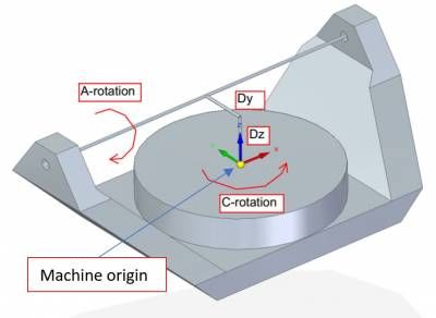
RosettaCNC G-code language

Gcode       Parameters Command                                       Description
                            High Speed Peck Drilling Cycle
G73         X Y Z R Q
                            Chip Break Drilling Cycle
G80                         Cancel motion mode
G81         XYZRL           Drilling Cycle
G82         XYZRLP          Drilling Cycle, Dwell
G83         XYZRLQ          Peck Drilling Cycle
G85         XYZRL           Boring Cycle, Feed Out
                            Boring Cycle, Spindle Stop, Rapid Move
G86         XYZRLP
                            Out
G88                         Boring Cycle, Spindle Stop, Manual Out
G89                         Boring Cycle, Dwell, Feed Out
G90                         Set absolute distance mode
                                                                     Absolute distance mode for I, J & K offsets. When
                                                                     G90.1 is in effect I and J both must be specified with
G90.1                       Set absolute arc distance mode
                                                                     G2/3 for the XY plane or J and K for the XZ plane or
                                                                     it is an error
G91                         Set incremental distance mode
G91.1                       Set incremental arc distance mode        Default arc mode
G92         axes            Set origin offsets
                                                                     Reset parameters 5211 - 5219 to zero but G92
G92.1                       Reset origin offsets                      keeps its current state. Parameter 5210 remains 1
                                                                     or 0 depending on its value before calling G92.1.
G92.2                       Suspend origin offsets
                                                                     Set the G92 offsets to the values saved in
G92.3                       Resume origin offsets
                                                                     parameters 5211 to 5219.
G93                         Enable feed per inverse of time
                                                                     When this G code is processed the target feed is set
G94                         Enable feed per minute                   to 0 and should be specified again using F.
G98                         Canned cycle return mode                 Initial Level Return In Canned Cycles set to initial Z
                                                                     Initial Level Return In Canned Cycles set to R
G99                         Canned cycle return mode
                                                                     parameter
G100        PABC…           Internal PLC function Call
                                                                     Request the axes specified by the P parameter to
G101        P               Set the axes to be interpolated          be interpolated. The P parameter is a bitmask
                                                                     where bit 1 represents X axis, bit 2 Y axis, ….
                                                                     Request the axes specified by the P parameter to
G102        P               Homing request                           be homed. The P parameter is a bitmask where bit
                                                                     1 represents X axis, bit 2 Y axis, ….
                                                                     The maximum speed used for G0 motion. Units are
G103        V               Set traverse rate                        mm/min. Zero means use the maximum value
                                                                     allowed by the axes involved in the movement.
                                                                     Set the maximum acceleration and deceleration
                                                                     along the trajectory during interpolated motion.
                                                                     When A/D is set to 0 the maximum
                                                                     acceleration/deceleration allowed by the axes
                                                                     involved in the movement is used.
                                                                     Units are mm/s^2 if G21 is active and inches/s^2 if
G104        A D          Set interpolated motion dynamics         G20 is active.
                                                                     Example: G104 A100 D50 to set a maximum
                                                                     acceleration of 100 mm/s^2 and a maximum
                                                                     deceleration of 50 mm/s^2.
                                                                     J is optional and can be used to set the jerk in %
                                                                     from 0.0 to 100.0. 0 Means accelerate with a slower
                                                                     ramp, 100% means accelerate immediately.
                                                                     User defined G codes require a user edited G-code
G200÷G499   ABC…            User defined G codes                      file in macros folder with the G-code name (eg:
                                                                     g212.ngc).

                                                  9/75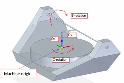
RosettaCNC G-code language

1.2 Supported M Codes

Mcode Parameters Command                            Description
M0                      Program Stop                Pause a running program temporarily
M1                      Program Optional Stop       Pause a running program temporarily if the optional stop input is on.
                                                    End a G-code program and reset the machine state: switch off I/O, mist,
M2                      Program End
                                                    flood and spindle.
M3                      Start spindle clock wise
                        Start spindle counter
M4
                        clock wise
M5                      Stop spindle turning
M6                      Tool change                 See also User Tool Change Subprogram
M7                      Mist On
M8                      Flood On
M9                      Mist and Flood Off
                        Turn On Torch Height
M17
                        Control (THC)
                        Turn Off Torch Height
M18
                        Control (THC)
                        Pallet shuttle and          If the correspondent settings is enabled the user G-code macro
M30
                        program end                 pallet_shuttle.ngc can be called.
                        Restart program
M47
                        execution
                        Enable the feed rate
M48                     and spindle speed
                        override controls
                        Disable the feed rate
M49                     and spindle speed
                        override controls
                                                    P parameter is optional and if it is not specified P0 is considered.
                                                    Possible P values are:
                                                    •
                                                    0 disable feed override
                        Enable/Disable the feed     •
M50                                              1 enable feed override
                        rate override control.
                                                    •
                                                    2 enable feed override custom 1
                                                    •
                                                    3 enable feed override custom 2
                        Enable/Disable the
                                                    Usage: M51 P1 (or M51) enable spindle speed override control and M51
M51                  spindle speed override
                                                    P0 disable it. The P parameter is optional.
                        control.
                                                    If the correspondent settings is enabled the user G-code macro
M60                     Pallet shuttle
                                                    pallet_shuttle.ngc can be called.
                        Set the current tool
                                                    Could be called from user G-code defined tool change macro, see also
M61      Q              without performing a
                                                    User Tool Change Subprogram.
                        tool change.
M62      P              Turn out ON
M63      P              Turn out OFF
                                                    Parameters:
                                                    •
                                                    P: the number of the user input signal to be waited
                                                    •
                                                    L:
                                                       ⚬
                                                    0: waits for the selected input to reach the LOW state
                                                       ⚬
                                                    1: waits for the selected input to reach the HIGH state
                                                       ⚬
                                                    2: waits for the selected input to perform a FALL event
                                                       ⚬
M66      PLQ            Wait input                  3: waits for the selected input to perform a RISE event
                                                       ⚬
                                                    4: return immediately and the input value is stored in #5720
                                                       ⚬
                                                    10 to 13: wait for the input to be LOW, HIGH, FALL or RISE and generate a CNC alarm if
                                                    timeout elapses while waiting
                                                    •
                                                    Q: timeout in seconds (optional)
                                                    Notes:
                                                    •
                                                    If the correspondent compiler setting is enabled the input value is stored in parameter #5720 and can be used
                                                    in the following control flow statements (IF, WHILE, …).
                                                    •
                                                    If the Q parameter is missing, the instruction waits until the condition is satisfied.

M67      P              Read analog input           Work the same way of M66 but is used to handle analog inputs
                                                    Used instead of M62/M63 for analog outputs. Q argument is used to set
M68      PQ             Set analog output
                                                    the desired analog output value in percentage.
M98      PL             Call Subroutine             Note: a named external subroutine can be called
M99                     Return from Subroutine

                                                   10/75
RosettaCNC G-code language
Mcode Parameters Command Description
End Program without End a program but does not perform an automatic reset switching off
M102
reset mist, flood, spindle status, …
This M code is intended to be called by the user from the file named
tool_change.ngc. This code inform the PLC to start the internal tool
Execute PLC internal
M106 change procedure that can perform a few automatic actions not
tool change procedure
described by the procedure described using the G-code. See also User
Tool Change Subprogram.
Inform the PLC that the tool change procedure written in the User Tool
M107
Change Subprogram has started.
Inform the PLC that the tool change procedure written in the User Tool
M108
Change Subprogram has ended.
M109 PQD Show user message
M120 PQD Show user media
The parameter P identifies the group. This M code updates the
M166 P Read digital input group
parameters #5740- #5759
Read analog input The parameter P identifies the group. This M code updates the
M167 P
group parameters #5740- #5759
User defined M codes require a user edited G-code file with the macro
name and .ngc extension to be place in the directory
M200÷M299 ABC… User defined M codes
/machines//macros (eg:
m210.ngc).
11/75RosettaCNC G-code language
1.3 Other Codes
Simple G-code commands are used for setting the speed, feed, and tool parameters.
“F” for “Feed”
The F command sets the feed rate; the machine operates at the set feed rate when G1 is used, and subsequent G1 commands
will execute at the set F value.
If the feed rate (F) is not set once before the first G1 call, either an error will occur or the machine will operate at its “default”
feed rate.
An example of a valid F command: G1 F1500 X100 Y100
To see how RosettaCNC handled the feed rate when for single rotary axis moves or for mixed moves please check Feed
Management
“S” for “Spindle Speed”
The S command sets the spindle speed, typically in revolutions per minute (RPM). An example of a valid S command: S10000
“T” for “Tool”
The T command is used to set the id of the tool to be loaded with the M6 command.
The typical syntax to load the tool with id 1 would be:
M6 T1
Notes
Setting the Tool Change Type option to Macro in the Board Settings the user can customize the tool
change procedure.
If the option is enabled the M06 command will look into the machine macros folder and execute the G-code
file named tool_change.ngc.
In this file the user can specify any supported G-code command to perform the tool change procedure as
required by the specific machine.
To see a reference implementation of the file tool_change.ngc please take a look to User Tool Change
Subprogram.
1.4 G-Code Comments
The following syntaxes are supported:
(…) : simple comment between brackets
; : simple comment till the end of the line started with a semi column
1.5 Block delete
Block Delete, also called Optional Skip, determines what happens when a line of code has a forward slash mark (/).
In RosettaCNC integrated G-Code editor there is a dedicated icon to enable/disable this feature. When the feature is enabled
and a line of G-Code begins with a forward slash the line is ignored and the execution skips to the next line of code.
12/75RosettaCNC G-code language
1.6 Go to predefined positions
1.6.1 G28 and G28.1
G28 uses the values stored in parameters 5161-5166 as the X Y Z A B C final point to move to.
The parameter values are absolute machine coordinates
G28 - makes a rapid move from the current position to the absolute position of the values in parameters
5161-5166. Since the position stored in the parameters 5161-5166 is considered absolute the tool offset
enabled with G43 influences the position. Example: #5163 = 0, tool_offset_z = 50 → target_position =
#5163 - tool_offset_z = -50.
G28 axes - makes a rapid move to the position specified by axes including any offsets, then will make a
rapid move to the absolute position of the values in parameters 5161-5166 for axes specified.
Any axis not specified will not move.
G28.1 - stores the current absolute position into parameters 5161-5166. Note: G28.1 does not take any
argument, the current absolute machine position is stored.
Examples
G28 (rapid move to the values specified into the stored parameters, moving all axes)
G28 Z10.0 (rapid move to Z10.0 then to location specified in the G28 stored parameters, moving only Z)
G28 G91 Z0 (rapid relative move to relative Z0.0 then to location specified in the G28 stored parameters, moving only Z)
The last example skip the intermediate position, since the movement is relative and with a displacement of 0.
It is usually used to ensure that only axis Z will move to the homing position specified in G28 parameters.
1.6.2 G30 and G30.1
G30 uses the values stored in parameters 5181-5186 as the X Y Z A B C final point to move to.
The parameter values are absolute machine coordinates
G30 - makes a rapid move from the current position to the absolute position of the values in parameters
5181-5186.
G30 axes - makes a rapid move to the position specified by axes including any offsets, then will make a
rapid move to the absolute position of the values in parameters 5181-5186 for axes specified.
Any axis not specified will not move.
G30.1 - stores the current absolute position into parameters 5181-5186. Note: G30.1 does not take any
argument, the current absolute machine position is stored.
1.6.2.1 Examples
13/75RosettaCNC G-code language
( © 2018 by RosettaCNC Motion )
( file name: g28_example.ngc )
G17 G21 G40 G49 G50 G54 G69 G90
#5161=20 ( G28 X )
#5162=40 ( G28 Y )
#5163=20 ( G28 Z )
G52 X20 Y20
G28 G91 Z0
M98 P1000
; Since Z axis is specified only axis Z will be moved to the
; position stored in parameter 5163.
; Since the intermediate point Z0 is specified with G91 the
; intermediate point position will be skipped.
G28 G91 Z0
G90
G52 X50 Y50
M98 P1000
; If no axis is specified with the G28 the position stored in
; the parameters 5161-5166 is used.
G28
M2
( Square )
O1000
G90
G0 X0 Y0 Z0
G1 X10
Y10
X0
Y0
M99
14/75RosettaCNC G-code language
1.7 G Code Order of Execution
The order of execution of items on a line is defined not by the position of each item on the line, but by the following list:
the entire line is skipped if it starts with a forward slash / and the block delete toggle is active
comments started with ( or ;
if N is the first letter of a line the following number is interpreted as line number
when a subroutine declaration is found (example O1001) the remaining part of the line is allowed only to
be a comment.
control flow statements like WHILE,IF
set feed rate mode G93, G94
set feed rate F
set spindle speed S
I/O handling: M62, M63, M66
change tool: M6 if user tool change macro is disabled, M61, M106
spindle on or off: M3, M4, M5
coolant on or off: M7, M8, M9, M17, M18
M48, M49
M109, M120
dwell G4
set active plane: G17, G18, G19
set length units: G20, G21
cutter radius compensation on or off: G40, G41, G42
cutter length compensation on or off: G43, G49
coordinate system selection: G54, G55, G56, G57, G58, G59, G59.1, G59.2, G59.3
set path control mode: G61, G61.1, G64
set distance mode: G90, G91
set arc mode: G90.1, G91.1
set retract mode: G98, G99
non modal G-codes: G10, G28, G28.1, G30, G30.1, G52, G92, G92.1, G92.2, G92.3
scaling: G50, G51
rotation: G68, G69
motion: G0, G1, G2, G3, G9, G76, G80
stop: M0, M1, M2, M30, M47
control flow statements like GOTO
subroutines and macros: M98, M6 only if user tool change macro is enabled
Some codes require to be the only G/M codes in the line, they are: G65, G100, user defined m codes and user defined g codes
15/75RosettaCNC G-code language
1.8 Arcs & Helices
A circular or helical arc is specified using either G2 (clockwise arc) or G3 (counterclockwise arc) at the current feed rate.
The direction (CW, CCW) is as viewed from the positive end of the axis about which the circular motion occurs.
The plane used for the circle or helix must be one between XY, YZ, or XZ.
The plane is selected with G17 (XY-plane), G18 (XZ-plane), or G19 (YZ-plane).
The P word can be used to specify the number of full turns plus the programmed arc.
The P word must be an integer. If P is unspecified, the behaviour is as if P1 was given: that is, only one full or partial turn will
result.
For each P increment above 1 an extra full circle is added to the programmed arc.
Multi turn helical arcs are supported and give motion useful for milling holes or threads.
Note If a line of code makes an arc and includes rotary axis motion, the rotary axes turn so that the rotary motion starts and
finishes when the XYZ motion starts and finishes.
1.8.1 Syntax
1.8.2 Center Format Arcs
Center format arcs are more accurate than radius format arcs and are the preferred format to use.
The end point of the arc along with the offset to the center of the arc from the current location are used to program arcs that
are less than a full circle.
If the end point of the arc is the same as the current location a full circe is generated.
G2 or G3 axes offsets P
G2 or G3 offsets P can be used for full circles
Incremental Arc Distance Mode
This is the default Distance Mode for the arc center offsets (I, J, K) that are relative distances from the start location of the
arc.
One or more axis words and one or more offsets must be programmed for an arc that is less than 360 degrees.
This mode is enabled with G91.1.
16/75RosettaCNC G-code language
Absolute Arc Distance Mode
Arc center offsets (I, J, K) are relative distances from the current origin of the axes.
One or more axis words and both offsets must be programmed for arcs less than 360 degrees.
This mode is enabled with G90.1.
1.8.3 Radius Format Arcs
G2 or G3 axes R- P
1.8.4 Examples
1.8.5 Center format arcs incremental mode
17/75RosettaCNC G-code language
1.8.6 Full circles and helices
( © 2018 by RosettaCNC Motion )
( file name: full_circles_and_helices.ngc )
G21 G40 G49 G90 G54 G50 G69
M3 F2000
G0 X0 Y0 Z0
G17 ; XY plane
G2 I0 J25
G18 ; XZ plane
G2 I0 K25
G19 ; YZ plane
G2 J0 K25
T3 M6
G52 X100
G0 X0 Y0 Z0
; helixes
G17
G2 I0 J25 Z100 P2
G0 X0 Y0 Z0
G18 ; XZ plane
G2 I0 K25 Y100 P2
G0 X0 Y0 Z0
G19 ; YZ plane
G2 J0 K25 X100 P2
M2
18/75RosettaCNC G-code language
2. G-Code variables
Rosetta CNC supports Macro programming (following Fanuc Macro B style).
Your G-Code programs or sub-programs can include a few non G-Code commands that use variables, arithmetic, logic
statements, and looping are available.
Rosetta CNC supports 7000 variables that can be accessed from the G-code. These variables are divided into 5 groups as
described in the following table.
Variable Number Type of Variable Function
#0 Null #0 is read only and its value is always “null” that means “no value”.
#1-#33 Local Variables Local variables are used to pass arguments to macros and as temporary scratch storage.
The value of these variables can be set by the user through the GUI and the value in the table will
#100-#499 Input Variables
never be changed by the controller.
The value of these variables can be read/write by G-code programs and are initialized with #0
#500-#3999 Program Variables
before executing a program.
The value of these variables is shared between the GUI interface and the controller.
#4000-#4999 Shared Variables The result is that if during a program one of these variables is changed the user can see the
updated final value in the table.
#5000-#5999 System Variables Updated run time by the compiler
Variables that can be modified by the user only before compilation and that are password protected.
#6000-#6999 Protected Variables
A G-code program can only read these variables and not write them.
2.1 System variables description
System Variable Meaning
Current Position Variables Current Position variables Meaning
5001-5006 Current TCP position X – C See position information table
5081-5086 Current TCP position when restarting X - C
5091-5093 Last stop position X, Y, Z [inches or mm depending on parameter 5106]
5094-5096 Last stop position A, B, C
Active G-codes Variables Active G-codes Variables Meaning
5100 Sequence number of lines executed
5101 Group 01: G0, G1, G2, G3, G38.X, G73, G80, G81, G82, G83, G84, G85, G86, G87, G88, G89
5102 Group 02: G17, G18, G19
5103 Group 03: G90, G91
5104 Group 04: G90.1, G91.1
5105 Group 05: G93, G94
5106 Group 06: G20, G21
5107 Group 07: G40, G41, G41.1, G42, G42.1
5108 Group 08: G43, G43.1, G43.2, G43.4, G43.7, G49
5110 Group 10: G98, G99
5111 Group 11: G50, G51
5112 Group 12: G54, G55, G56, G57, G58, G59, G59.1, G59.2, G59.3
5113 Group 13: G61, G61.1, G64
5116 Group 16: G68, G69
5117 Group 17: G15, G16
Other codes Other codes meaning
5120 Interpolated-Grouprd axes mask. Value is a bitmask where bit 1 represents X axis, bit 2 Y axis, ..
5127 Active jerk [%]
5128 Active max acceleration [mm/s^2 or inches/s^2] (0 means use the maximum acceleration)
5129 Active max deceleration [mm/s^2 or inches/s^2] (0 means use the maximum deceleration)
5130 Active feed rate (F)
5131 Active spindle speed (S)
5132 Selected tool (T)
5133 Selected slot
5134 Current tool
5135 Current slot
5136 Active feed rate override mode, P argument of M50
5137 Active spindle speed override mode, P argument of M51
Active traverse rate: target speed during G0 commands. 0 means use the maximum possible speed.
5138
[mm/s^2 or inches/s^2]
5140 Tolerance set with G64 P
5141 Points removal threshold set with G64 Q
5148 While a modal macro is active it stores how many times a modal macro (G66) has been called.
19/75RosettaCNC G-code language
System Variable Meaning
Current Position Variables Current Position variables Meaning
Executing sub-program. Flag set to 1 while G-code is executing a sub-program called from the main
5149
program.
Active M-codes Active M-codes meaning
5150 M0, M2, M30, M47, M60
5151 M3, M4, M5
5152 M6, M106
5153 M7, M9
5154 M8, M9
G28, G28.1 Variables G28, G28.1 Variables Meaning
5161 G28.1 position X
5162 G28.1 position Y
5163 G28.1 position Z
5164 G28.1 position A
5165 G28.1 position B
5166 G28.1 position C
G30, G30.1 Variables G30, G30.1 Variables Meaning
5181 G30.1 position X
5182 G30.1 position Y
5183 G30.1 position Z
5184 G30.1 position A
5185 G30.1 position B
5186 G30.1 position C
WCS Offsets Variables WCS Offsets Variables Meaning
5201 - 5206 G52 offset X - C
5210 G92 enabled (0 ÷ 1)
5211 - 5216 G92 offset X - C
WCS Variables WCS Variables Meaning
5220 Coord. System number
5221 - 5226 Coord. System 1 X – C
5241 - 5246 Coord. System 2 X – C
5261 - 5266 Coord. System 3 X – C
5281 - 5286 Coord. System 4 X – C
5301 - 5306 Coord. System 5 X – C
5321 - 5326 Coord. System 6 X – C
5341 - 5346 Coord. System 7 X – C
5361 - 5366 Coord. System 8 X – C
5381 - 5386 Coord. System 9 X – C
Tool Variables Tool Variables Meaning
5400 Current tool id
5401 Current tool offset X
5402 Current tool offset Y
5403 Current tool offset Z / Current tool length
5410 Current tool diameter
5411 Current tool type
5412 Current tool parameter 1
5413 Current tool parameter 2
5414 Current tool parameter 3
5420 Tool compensation offset X (Set using G43, G43.1, G43.2, G43.4, G43.7, G49)
5421 Tool compensation offset Y (Set using G43, G43.1, G43.2, G43.4, G43.7, G49)
5422 Tool compensation offset Z (Set using G43, G43.1, G43.2, G43.4, G43.7, G49)
5423 Tool compensation offset A (Set using G43, G43.1, G43.2, G43.4, G43.7, G49)
5424 Tool compensation offset B (Set using G43, G43.1, G43.2, G43.4, G43.7, G49)
5425 Tool compensation offset C (Set using G43, G43.1, G43.2, G43.4, G43.7, G49)
5426 The id of the tool used for RTCP compensation (G43.4/G43.7)
Scaling & Rotation Variables Scaling and Rotation Variables Meaning
5501 G51 scaling factor X
5502 G51 scaling factor Y
5503 G51 scaling factor Z
5504 G51 offset X
5505 G51 offset Y
5506 G51 offset Z
5510 G68 rotation plane
20/75RosettaCNC G-code language
System Variable Meaning
Current Position Variables Current Position variables Meaning
5511 G68 rotation XY
5512 G68 rotation XZ
5513 G68 rotation YZ
5514 G68 offset X
5515 G68 offset Y
5516 G68 offset Z
Runtime External Variables Runtime External Variables Meaning
Probe state at the end of a G38.X. Values: 1 probing procedure succeeded, -1 failed: sensor not tripped
5700
before reaching the target position, -2 failed: sensor already tripped
Probed position loaded at the end of a G38.X with respect to the active WCS See position information
5701 - 5706
table
Probed position X - C loaded at the end of a G38.X with respect to machine coordinates See position
5711 - 5716
information table
5720 Return value for M66
5721 Return value for M109 and M120
5722 Status of the last M66 (0 → Success, 1 → Failure)
5730-5734 User input values from M109 or M120
5735-5739 User input values from M109 or M120
5740-5744 Input values for M166 and M167
5745-5749 Input values for M166 and M167
5750-5754 Input values for M166 and M167
5755-5759 Input values for M166 and M167
Parameters Related Variables Parameters Related Variables (Set using G10 L100 P V)
5800 The motion mode used when G66 is enabled (0 → G0; 1 → G1)
5801 Rotary axis modulus used for the rollover
5802 Axis A rotary mode (see Rotary axis options)
5803 Axis B rotary mode (see Rotary axis options)
5804 Axis C rotary mode (see Rotary axis options)
Restart related position variables Meaning
5091-5096 Last stop positions. X,Y and Z in inches or mm depending on parameter 5106 and A,B,C in deg
2.2 Named variables
Named variables work like normal numbered variables but are easier to read.
Syntax:
Named variables must be enclosed between < > marks.
All variable names are converted to lower case and have spaces and tabs removed, so and < Nam ed Var i Able> represent to the very same variable.
A named variable starts to exist when it is assigned a value for the first time.
You can check if a named parameter already exists with the unary operation EXISTS[arg].
Example: IF [EXISTS[#] EQ 0] THEN GOTO 10
When a macro is called the passed arguments can be read using the correspondent named variable
preceded by _args. Example: to get the value of the x argument you can use #.
2.2.1 Global and local scopes
A named parameter whose name starts with _ is local to the scope in which it is created. A local named variable vanishes when
its scope is left. Indeed, when a local variable is declared in a subroutine and the subroutine returns, the variable is deleted and
cannot be referred to anymore.
# is a global named variable.
# is a local named variable.
2.2.2 Indexing support
21/75RosettaCNC G-code language
Both global and local variables support indexing with a syntax similar to C style arrays.
Every expression between brackets ([,]) in a variable name is evaluated by the G-code interpreter.
Examples:
# is evaluated as # if # has been
previously set to 10.
#is evaluated depending on the variables
# and #
2.2.3 Pre-defined Named Parameters
The G-Code compiler has a pre-defined set of read-only named parameters which can be useful in the Program/Macro/MDI
editing.
There are nine groups:
1. # which contains info about the system.
2. # which contains usefull math constants.
3. # which contains some of CNC setup settings.
4. # which contains usefull compile constants.
5. # which contains usefull axis constants.
6. # which contains usefull tool constants.
7. # which contains usefull probe constants.
8. # which contains usefull M66 wait constants.
9. # which contains usefull ATCM constants.
Named Variable Description
# The major version of CNC System (e.g. returns 0 of 0.3.6.17 version)
# The minor version of CNC System (e.g. returns 3 of 0.3.6.17 version)
# The release version of CNC System (e.g. returns 6 of 0.3.6.17 version)
# The build version of CNC System (e.g. returns 17 of 0.3.6.17 version)
# The customer ID (usually values 0)
# Interface Level (for Control Software 1.8.7 will be 8)
User Interface units mode:
# 20 = Imperial (in)
21 = Metric (mm)
# Max value (1.7e+308)
# Min value (5e-324)
# NaN value (-NAN)
# Infinity value (+INF)
# Negative infinity value (-NAN)
# Euler's number (2.7182818284590452354)
# Archimedes constant (3.14159274101257324218)
# Natural Log of 2 (0.69314718055994530942)
# Natural Log of 10 (2.30258509299404568402)
# Natural Log of pi (1.14472988584940017414)
# Factor to convert inches to mm (25.4)
# Factor to convert mm to inches (1/25.4)
# Factor to convert deg to rad (PI/180)
# Factor to convert rad to deg (180/PI)
Describes the modality of G-Code compilation (see # section for a
#
detailed description)
Contains the staring G-Code line for the compile modes
# # and
#
22/75RosettaCNC G-code language
Named Variable Description
Machine Type:
#
0 = Mill
Kinematics Model:
0 = Trivial
1 = Indipendent Rotational Axes
#
2 = Rotary Table AC
3 = Rotary Table BC
4 = Tilting Spindle AC
# X Axis Type (see # section for a detailed description)
# X Axis Max Velocity [mm/min]
# X Axis Acceleration [mm/s²]
# X Axis Min Limit [mm]
# X Axis Max Limit [mm]
# Y Axis Type (see # section for a detailed description)
# Y Axis Max Velocity [mm/min]
# Y Axis Acceleration [mm/s²]
# Y Axis Min Limit [mm]
# Y Axis Max Limit [mm]
# Z Axis Type (see # section for a detailed description)
# Z Axis Max Velocity [mm/min]
# Z Axis Acceleration [mm/s²]
# Z Axis Min Limit [mm]
# Z Axis Max Limit [mm]
# A Axis Type (see # section for a detailed description)
# A Axis Max Velocity [mm/min]
# A Axis Acceleration [mm/s²]
# A Axis Min Limit [mm]
# A Axis Max Limit [mm]
A Axis Motion Mode:
# 0 = Continuous
1 = Indexing
A Axis Convention:
# 0 = Normal
1 = Inverse
A Axis Wrapped Rotary State:
# 0 = Disabled
1 = Enabled
A Axis Parallet to:
0=X
#
1=Y
2=Z
A Axis Origin Mode:
0 = Custom
1 = WCS 1 - G54
2 = WCS 2 - G55
3 = WCS 3 - G56
# 4 = WCS 4 - G57
5 = WCS 5 - G58
6 = WCS 6 - G59
7 = WCS 7 - G59.1
8 = WCS 8 - G59.2
9 = WCS 9 - G59.3
# A Axis Origin X [mm]
# A Axis Origin Y [mm]
# A Axis Origin Z [mm]
# B Axis Type (see # section for a detailed description)
# B Axis Max Velocity [mm/min]
# B Axis Acceleration [mm/s²]
# B Axis Min Limit [mm]
# B Axis Max Limit [mm]
B Axis Motion Mode:
# 0 = Continuous
1 = Indexing
23/75RosettaCNC G-code language
Named Variable Description
B Axis Convention:
# 0 = Normal
1 = Inverse
B Axis Wrapped Rotary State:
# 0 = Disabled
1 = Enabled
B Axis Parallet to:
0=X
#
1=Y
2=Z
B Axis Origin Mode:
0 = Custom
1 = WCS 1 - G54
2 = WCS 2 - G55
3 = WCS 3 - G56
# 4 = WCS 4 - G57
5 = WCS 5 - G58
6 = WCS 6 - G59
7 = WCS 7 - G59.1
8 = WCS 8 - G59.2
9 = WCS 9 - G59.3
# B Axis Origin X [mm]
# B Axis Origin Y [mm]
# B Axis Origin Z [mm]
# C Axis Type (see # section for a detailed description)
# C Axis Max Velocity [mm/min]
# C Axis Acceleration [mm/s²]
# C Axis Min Limit [mm]
# C Axis Max Limit [mm]
C Axis Motion Mode:
# 0 = Continuous
1 = Indexing
C Axis Convention:
# 0 = Normal
1 = Inverse
C Axis Wrapped Rotary State:
# 0 = Disabled
1 = Enabled
C Axis Parallet to:
0=X
#
1=Y
2=Z
C Axis Origin Mode:
0 = Custom
1 = WCS 1 - G54
2 = WCS 2 - G55
3 = WCS 3 - G56
# 4 = WCS 4 - G57
5 = WCS 5 - G58
6 = WCS 6 - G59
7 = WCS 7 - G59.1
8 = WCS 8 - G59.2
9 = WCS 9 - G59.3
# C Axis Origin X [mm]
# C Axis Origin Y [mm]
# C Axis Origin Z [mm]
# U Axis Type (see # section for a detailed description)
# U Axis Max Velocity [mm/min]
# U Axis Acceleration [mm/s²]
# U Axis Min Limit [mm]
# U Axis Max Limit [mm]
# V Axis Type (see # section for a detailed description)
# V Axis Max Velocity [mm/min]
# V Axis Acceleration [mm/s²]
# V Axis Min Limit [mm]
# V Axis Max Limit [mm]
# W Axis Type (see # section for a detailed description)
24/75RosettaCNC G-code language
Named Variable Description
# W Axis Max Velocity [mm/min]
# W Axis Acceleration [mm/s²]
# W Axis Min Limit [mm]
# W Axis Max Limit [mm]
# Spindle Max Speed [rpm]
# Rotary Table D:X [mm]
# Rotary Table D:Y [mm]
# Rotary Table D:Z [mm]
# Tilting Spindle H:X [mm]
# Tilting Spindle H:Y [mm]
# Tilting Spindle H:Z [mm]
# Tilting Spindle J:X [mm]
# Tilting Spindle J:Y [mm]
# Tilting Spindle J:Z [mm]
# The G-Code compiler is compiling an MDI command
The G-Code compiler is compiling a Macro (from User Input or a Top Toolbar
#
Button)
# The G-Code compiler is compiling the main Program
The G-Code compiler is compiling the main Program starting from a specified line
#
of code
The G-Code compiler is compiling the main Program for a RESUME command after
#
a STOP command
The G-Code compiler is compiling the main Program for a RESUME from specific
#
line after a STOP command
#You can also read