Wireless Gateway ARG600 Dual SIM Variant - User Manual
←
→
Page content transcription
If your browser does not render page correctly, please read the page content below
—
Wireless Gateway
ARG600 Dual SIM Variant
User Manual

Document ID: 1MRS758460
                    Issued: 2021-05-31
                            Revision: F
                  Product version: 3.4.7

© Copyright 2021 ABB. All rights reserved
Copyright
            This document and parts thereof must not be reproduced or copied without written
            permission from ABB, and the contents thereof must not be imparted to a third
            party, nor used for any unauthorized purpose.

            The software or hardware described in this document is furnished under a license
            and may be used, copied, or disclosed only in accordance with the terms of such
            license.

            Trademarks
            ABB is a registered trademark of the ABB Group. All other brand or product
            names mentioned in this document may be trademarks or registered trademarks of
            their respective holders.

            Warranty
            Please inquire about the terms of warranty from your nearest ABB representative.

             abb.com/mediumvoltage
Disclaimer
The data, examples and diagrams in this manual are included solely for the concept
or product description and are not to be deemed as a statement of guaranteed
properties. All persons responsible for applying the equipment addressed in this
manual must satisfy themselves that each intended application is suitable and
acceptable, including that any applicable safety or other operational requirements
are complied with. In particular, any risks in applications where a system failure
and/or product failure would create a risk for harm to property or persons
(including but not limited to personal injuries or death) shall be the sole
responsibility of the person or entity applying the equipment, and those so
responsible are hereby requested to ensure that all measures are taken to exclude or
mitigate such risks.
This product has been designed to be connected and communicate data and
information via a network interface which should be connected to a secure
network. It is the sole responsibility of the person or entity responsible for network
administration to ensure a secure connection to the network and to take the
necessary measures (such as, but not limited to, installation of firewalls, application
of authentication measures, encryption of data, installation of anti virus programs,
etc.) to protect the product and the network, its system and interface included,
against any kind of security breaches, unauthorized access, interference, intrusion,
leakage and/or theft of data or information. ABB is not liable for any such damages
and/or losses.
This document has been carefully checked by ABB but deviations cannot be
completely ruled out. In case any errors are detected, the reader is kindly requested
to notify the manufacturer. Other than under explicit contractual commitments, in
no event shall ABB be responsible or liable for any loss or damage resulting from
the use of this manual or the application of the equipment. In case of discrepancies
between the English and any other language version, the wording of the English
version shall prevail.Safety information
Dangerous voltages can occur on the connectors, even though the
auxiliary voltage has been disconnected.
Non-observance can result in death, personal injury or substantial
property damage.
Only a competent electrician is allowed to carry out the electrical
installation.
National and local electrical safety regulations must always be
followed.
This product is not fault-tolerant and is not designed, manufactured
or intended for use or resale as on-line control equipment or as part
of such equipment in any hazardous environment requiring fail-safe
performance, such as in the operation of nuclear facilities, aircraft
navigation or communication systems, air traffic control, direct life
support machines, or weapons systems, in which the failure of the
hardware or software described in this manual could lead directly to
death, personal injury, or severe physical or environmental damage.
To prevent damage both the product and any terminal devices must
always be switched off before connecting or disconnecting any
cables. It should be ascertained that different devices used have the
same ground potential. The output voltage of the power supply
should be checked before connecting any power cables.
The devices mentioned in this manual are to be used only according
to the instructions described in this manual. Faultless and safe
operation of the devices can be guaranteed only if the transport,
storage, operation and handling of the devices is appropriate. This
also applies to the maintenance of the products.Table of contents
Table of contents
Section 1 Introduction.......................................................................3
This manual........................................................................................ 3
Intended audience.............................................................................. 3
Product documentation.......................................................................3
Product documentation set............................................................3
Document revision history............................................................. 3
Related documentation..................................................................4
Symbols and conventions...................................................................4
Symbols.........................................................................................4
Document conventions.................................................................. 5
Section 2 ARG600 overview............................................................ 7
Overview.............................................................................................7
Physical interfaces..............................................................................8
Front panel.................................................................................... 8
Back panel...................................................................................10
DIN rail mounting..............................................................................13
Product information label .................................................................13
Firmware version.............................................................................. 13
Section 3 Getting started................................................................15
Connecting cables............................................................................ 15
Connection principle.................................................................... 15
Logging in......................................................................................... 15
User interface.............................................................................. 16
Ethernet port roles............................................................................ 16
Setting Ethernet port function to LAN............................................... 17
Configuring mobile WAN.................................................................. 17
Configuring the default route............................................................ 17
Section 4 Network configuration.....................................................19
Defining host and domain names..................................................... 19
Configuring communication interfaces............................................. 19
Configuring Ethernet LAN............................................................19
Configuring Ethernet WAN.......................................................... 19
Configuring the mobile WAN interface........................................ 19
Setting WAN failover and backup routing....................................20
Routing parameters.......................................................................... 21
Configuring the network monitor.......................................................21
Configuring DNS proxy.....................................................................22
ARG600 Dual SIM Variant 1
User ManualTable of contents
Checking network status.................................................................. 22
Section 5 Serial port configuration................................................. 23
Configuring serial ports.....................................................................23
Serial gateway.................................................................................. 23
Section 6 Additional system configuration......................................25
Changing passwords........................................................................ 25
Setting date and time........................................................................25
Restoring factory default settings..................................................... 26
Updating the firmware...................................................................... 26
Saving configuration profiles............................................................ 26
Section 7 Service configuration......................................................27
Configuring services......................................................................... 27
Service parameters.......................................................................... 27
Section 8 IEC-104 application settings...........................................31
The use of the IEC-104 protocol.......................................................31
Configuring IEC-104 application settings......................................... 31
IEC-104 application settings.............................................................31
Section 9 Modbus application settings........................................... 37
Modbus Gateway properties.............................................................37
Modbus mode...................................................................................38
Configuring the network master to serial slaves mode.....................39
Parameter settings........................................................................... 39
Section 10 Troubleshooting..............................................................43
Common troubleshooting issues...................................................... 43
Viewing the system log.....................................................................43
Section 11 Technical data................................................................ 45
Section 12 Glossary......................................................................... 49
2 ARG600 Dual SIM Variant
User Manual1MRS758460 F Section 1
Introduction
Section 1 Introduction
1.1 This manual
The user manual provides introductory information as well as detailed instructions
on how to set up and manage the device as part of a network environment.
1.2 Intended audience
This manual addresses the personnel involved in installing and managing the
devices.
The personnel is expected to be familiar with basic working principles of Internet
technology.
1.3 Product documentation
1.3.1 Product documentation set
Product series- and product-specific manuals can be downloaded from the ABB
Web site abb.com/mediumvoltage.
1.3.2 Document revision history
Document revision/date Product version History
A/2015-12-18 A First release
B/2017-09-22 3.4 Content updated to correspond to the
product version
C/2018-06-29 3.4.5 Content updated to correspond to the
product version
D/2019-04-24 3.4.7 Content updated to correspond to the
product version
E/2020-07-09 3.4.7 Content updated
F/2021-05-31 3.4.7 Content updated
Download the latest documents from the ABB Web site
abb.com/mediumvoltage.
ARG600 Dual SIM Variant 3
User ManualSection 1 1MRS758460 F
Introduction
1.3.3 Related documentation
Name of the document Description Document ID
Arctic Cyber Security Deployment 1MRS758860
Guideline
3G/LTE configuration guide Technical Configuring Wireless Gateways, 1MRS758449
Note Controllers and M2M Gateway
OpenVPN server in Wireless Configuring and using a static key 1MRS758450
Gateway/Controller Technical Note OpenVPN server/client in Wireless
Gateway and Controller products
3G/LTE Wireless Gateway firmware Updating firmware of Wireless 1MRS758451
update Technical Note Gateway devices
Product series- and product-specific manuals can be downloaded from the ABB
Web site abb.com/mediumvoltage.
1.4 Symbols and conventions
1.4.1 Symbols
The electrical warning icon indicates the presence of a hazard
which could result in electrical shock.
The warning icon indicates the presence of a hazard which could
result in personal injury.
The caution icon indicates important information or warning related
to the concept discussed in the text. It might indicate the presence
of a hazard which could result in corruption of software or damage
to equipment or property.
The information icon alerts the reader of important facts and
conditions.
The tip icon indicates advice on, for example, how to design your
project or how to use a certain function.
Although warning hazards are related to personal injury, it is necessary to
understand that under certain operational conditions, operation of damaged
4 ARG600 Dual SIM Variant
User Manual1MRS758460 F Section 1
Introduction
equipment may result in degraded process performance leading to personal injury
or death. Therefore, comply fully with all warning and caution notices.
1.4.2 Document conventions
A particular convention may not be used in this manual.
• Abbreviations and acronyms are spelled out in the glossary. The glossary also
contains definitions of important terms.
• Menu paths are presented in bold.
Select Main menu/Settings.
• Parameter names are shown in italics.
The function can be enabled and disabled with the Operation setting.
• Parameter values are indicated with quotation marks.
The corresponding parameter values are "On" and "Off".
ARG600 Dual SIM Variant 5
User Manual6
1MRS758460 F Section 2
ARG600 overview
Section 2 ARG600 overview
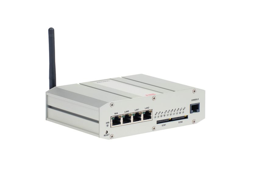
2.1 Overview
Wireless Gateway ARG600 provides wireless monitoring and control of field
devices via cellular network from a central site or a control center. The devices
offer industrial quality connectivity for the TCP/IP and serial port based protocols.
Wireless Gateway ARG600 exhibits integrated communication capability and
seamless integration to the SCADA systems.
Wireless Gateway ARG600 is a member of ABB’s Arctic product family and part
of its 600 Wireless Gateway product series.
By using Wireless Gateway ARG600, Ethernet and serial devices can be attached
to a TCP/IP based control system. With Wireless Gateway ARG600, conventional
IEC60870-101 devices can be attached to a modern TCP/IP based IEC
60870-5-104 control system. This is made possible by the protocol conversion
from IEC 60870-5-101 to IEC 60870-104. ARG600 also supports Modbus RTU to
Modbus TCP protocol conversion.DNP3 serial devices can be attached to a DNP3
TCP SCADA system. In this case, the DNP3 protocol is transferred over TCP/IP
communication (transparent serial gateway mode).
Wireless Gateway ARG600 can be utilized for various industrial and utility
applications to maximize the benefits.
• Industrial grade TCP/IP router: several serial and TCP/IP based field devices
can be integrated into a central supervisory and control system (SCADA)
• Integrated protocol conversion enables connecting the legacy serial-based
devices into a TCP/IP-based supervisory control system (SCADA)
• Ideal for retrofitting by allowing the user to extend the life cycle of existing
serial-based substation devices
• Remote access to field devices means less site visits for operations and
maintenance
• Optimizing the cost of communication by using public cellular networks
• Possibility to upgrade from the existing legacy's private radio system to a
higher bandwidth cellular network based solution. This enables to fully
maximize the usage of the existing application. For example, the video
surveillance of traffic can now be integrated into the same system.
ARG600 Dual SIM Variant 7
User ManualSection 2 1MRS758460 F
ARG600 overview
2.2 Physical interfaces
2.2.1 Front panel
1
2 3 4
GUID-CCA1FABA-FF13-4586-9C0A-4A05111345BD V1 EN-US
Figure 1: Front panel
1 LAN/WAN ports
2 Reset button
3 SIM card slots
4 Serial console port
Ethernet connector
The device has an RJ-45 connector for 10/100 Mbps Ethernet connection. The
maximum length of the Ethernet cable is 100 m.
Ethernet WAN
The device has one physical port for Ethernet WAN.
Table 1: Ethernet WAN specifications
Description Value
Number of ports 1
Speed 10Base-T, 100Base-TX
Duplex Half and Full
Autonegotiation Yes
Recommended cabling Cat5 or better
If the Ethernet WAN interface is directly connected to the computer, a crossover
cable must be used. The Ethernet WAN interface does not support automatic MDI/
MDIX detection.
8 ARG600 Dual SIM Variant
User Manual1MRS758460 F Section 2
ARG600 overview
Ethernet LAN
The device has three physical ports for Ethernet LAN. These ports are connected to
a common switch.
Table 2: Ethernet LAN specifications
Description Value
Speed 10Base-T, 100Base-TX
Duplex Half and Full
Autonegotiation Yes
Recommended cabling Cat5 or better
If the Ethernet LAN interface is directly connected to the computer, both the
crossover and straight cables can be used. The Ethernet LAN interface supports
automatic MDI/MDIX detection.
LEDs
The device has 11 status LEDs located on the front panel.
1
2 3 4 5 6 7 8 9 10 11
GUID-2F75FFBF-5082-49D1-951E-CDA1A690E70C V1 EN-US
Figure 2: LEDs
1 ERR
2 RUN
3 VPN
4 FW
5 SIM
6 SIG
7 COM
8 APP
9 USR
10 RS1
11 RS2
ARG600 Dual SIM Variant 9
User ManualSection 2 1MRS758460 F
ARG600 overview
Table 3: Description of available LEDs
LED Label State Description
1 ERR On Unit is restarting. LED should be
turned off after restart (usually about
30 seconds)
Flashing Error with power supply. Device
restarts constantly.
Off Device is operating normally
2 RUN Flashing Device is operating normally
Off If the unit is turned on and RUN LED
is not blinking, the system has an error
and is waiting for restart. The unit
should restart soon.
3 VPN On VPN connection is up
Flashing VPN connection is starting
Off VPN connection is disabled
4 FW - Reserved for future use
5 SIM On SIM card has been initialized and it is
ready for use
Flashing SIM card initialization is in progress
Off SIM card is not used
6 SIG On Signal level is normal or good
Flashing Signal level is weak
Off There is no signal
7 COM On Cellular network (Wireless WAN)
connection is up
Flashing Cellular connection is starting. If the
connection is not coming up, check
the SIM and SIG LEDs
Off Cellular connection is stopped
8 APP - Reserved for future use
9 USR - Reserved for future use
10 RS1 - Reserved for future use
11 RS2 - Reserved for future use
Reset button
It is possible to restore the factory settings by pushing the reset button for
approximately 15 seconds and releasing the button, when all the status LEDs are
illuminated. Any previous configuration will be lost after the reset.
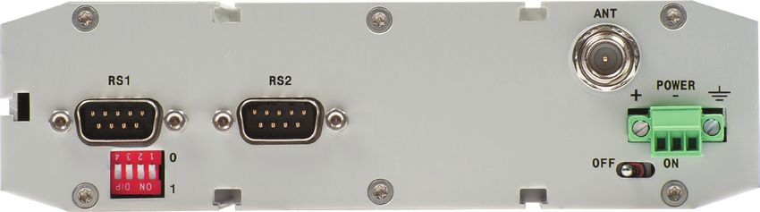
2.2.2 Back panel
The device has an antenna connector, a power supply connector, a power switch,
DIP switches and serial ports on the back panel.
10 ARG600 Dual SIM Variant
User Manual1MRS758460 F Section 2
ARG600 overview
1 2
3 4 5
GUID-023EC595-C917-40AE-A100-1DFCE0089287 V1 EN-US
Figure 3: Back panel
1 Application serial ports
2 Antenna connector FME (male)
3 DIP switches
4 Power switch
5 Power supply 12…36 VDC, limited (Section 2 1MRS758460 F
ARG600 overview
Recommended earthing
1
2
GUID-2829F418-6ED0-41C0-B466-9C904BDA8C8F V1 EN-US
Figure 5: Recommended earthing method
1 Cable (recommended min. 2.5 mm2)
2 Cable (recommended 1.5 mm2, max. length 120 mm)
The compliance tests have been done using this recommended earthing method.
Power switch
The power switch enables or disables the operation of the device.
DIP switches
The DIP switches select an application port (RS1) mode and settings (RS-232 or
RS-485). By default, all DIP switches are set to the 0 position (RS-232 mode). DIP
switches 2...4 apply only when DIP switch 1 is set to differential mode (RS-485/
RS-422).
Table 4: DIP switches
DIP switch Mode State Description
1 RS-232 or differential 0 = RS-232, 1 = Selects the serial port
RS-485 and RS-422 operation mode
2 DUPLEX 0 = FULL, 1 = HALF Selects between
RS-422 full-duplex (4-
wire) and RS-485 half-
duplex (2-wire)
differential modes
3 BIASING 0 = OFF, 1 = ON Enables RS-422
biasing on pins 2 and
8
4 TERMINATION 0 = OFF, 1 = ON Enables RS-422
termination on pins 2
and 8
12 ARG600 Dual SIM Variant
User Manual1MRS758460 F Section 2
ARG600 overview
If biasing and/or termination is required for the RS-485 half-duplex
(2-wire) mode, enable RS-422 biasing/termination with DIP
switches and manually connect pins 2-7 and 3-8 together at the
application port (RS-1).
2.3 DIN rail mounting
The device has mounting holes for optional DIN rail mounting brackets. The order
code for the DIN rail mounting kit is 2RCA028233 (DIN rail clips set consisting of
a plastic clip and screws).
2.4 Product information label
The product label contains basic information about the unit such as product name,
serial number and Ethernet MAC address.
2.5 Firmware version
The device's firmware version is visible on the welcome page (System/Welcome
Page), which is displayed after logging in to the device.
For firmware updates, contact ABB's technical customer support.
ARG600 Dual SIM Variant 13
User Manual14
1MRS758460 F                                                                                    Section 3
                                                                                           Getting started

Section 3                 Getting started

3.1                       Connecting cables

                          1.   Check that the power switch is in the OFF position.
                          2.   Connect the Ethernet cable between the device’s Ethernet LAN connector and
                               the computer used for the configuration.
                          3.   Connect the power supply to the device.
                          4.   Toggle the power switch to ON position.
                               The power/error LED and function LED should turn on immediately after the
                               power switch is turned on.

                          After the system has initialized, the function LED starts to flash.

3.1.1                     Connection principle
                          The device has configurable network interfaces.

                          •    Ethernet LAN
                          •    Ethernet WAN
                          •    Mobile WAN (SIM1 and SIM2)

                          The device supports cellular connectivity (2G, 3G, LTE) allowing the use of
                          wireless applications. The Mobile WAN interface is used for connecting the device
                          to the cellular network. The Ethernet LAN is used for connecting other Ethernet
                          devices to the device's local network.

                          The WAN interfaces can be configured to create a redundant system where one
                          WAN automatically receives traffic if the other one goes down. For example, if the
                          primary Ethernet connection goes down, the traffic is automatically switched to
                          mobile WAN (secondary connection) and back when the Ethernet interface comes
                          up again. Similarly, if two SIM cards are used, one is used as a primary WAN
                          connection and if it fails, the secondary SIM card is automatically taken into use.

3.2                       Logging in

                          1.   Configure the computer to use the same IP address space as the device.

ARG600 Dual SIM Variant                                                                                    15
User Manual
Section 3 1MRS758460 F
Getting started
Example: Laptop IP is 10.10.10.11 with netmask 255.255.255.0.
2. Check the IP configuration with the ping command in the command line.
3. In a Web browser, connect to the device over the HTTPS protocol using the
device’s IP address.
Example: The default IP address of the device is 10.10.10.10. The
corresponding address to enter in the browser is https://10.10.10.10/.
Ignore the browser's warning about a self-signed certificate.
4. Enter the username and password.
The default username is “arctic-adm“ and the default
password is “arcticm2m”. Change the password before
connecting the product to a public network.
5. Click Login.
The Home Page opens.
3.2.1 User interface
The user interface consists of views that can be opened from the menu in the left
pane.
3.3 Ethernet port roles
The device has three switched LAN ports and one WAN port.
• The LAN interface's IP address is by default 10.10.10.10/255.0.0.0. The LAN
IP address is a user configurable static address without a DHCP option.
• The WAN interface is configured by default as a DHCP client enabling the
ARG600 to obtain an IP address from an external DHCP server. Manual static
IP configuration is also possible for the WAN interface.
There are also two additional configuration options.
• Reversed: One Ethernet LAN port and three WAN ports
• Bridged: Unneeded WAN port can be bridged to LAN, thus amounting to a
total of four LAN ports
16 ARG600 Dual SIM Variant
User Manual1MRS758460 F Section 3
Getting started
3.4 Setting Ethernet port function to LAN
1. In the left pane, under Network, click Ethernet Port.
2. Set Port function to LAN.
3. Click Submit to save the settings.
3.5 Configuring mobile WAN
Install the SIM card before configuring the mobile WAN.
1. In the left pane, under Network, click Mobile WAN.
2. Enter the preferred configuration in the configuration fields.
3. Click Submit to save the settings.
3.6 Configuring the default route
1. In the left pane, under Network, click WAN Failover.
2. Set WAN Default Route to Yes.
This setting enables the use of the Ethernet WAN or the Mobile WAN as the
default route interface.
3. If configuring Ethernet WAN as the default gateway, in the left pane under
Network, click Ethernet Port and set Port function to WAN.
If configuring Mobile WAN as the default gateway, skip this step.
4. Set the default route.
• To select Ethernet WAN as the default gateway, under Primary WAN,
set Interface to Ethernet WAN.
• To select Mobile WAN as the default gateway, under Primary WAN,
set Interface to Mobile WAN.
5. If both Ethernet WAN and Mobile WAN are configured, under Backup
WAN, set Interface to Mobile WAN or Ethernet WAN, whichever is not
selected as the default gateway.
If the primary WAN interface comes down, the device automatically switches
the default route to the backup WAN interface.
6. Click Submit to save the settings.
7. Restart the device.
ARG600 Dual SIM Variant 17
User Manual18
1MRS758460 F                                                                            Section 4
                                                                             Network configuration

Section 4                 Network configuration

4.1                       Defining host and domain names

                          1.   In the left pane, under Systems, select General Settings.
                          2.   In the Hostname field, enter the name of the device without the domain part.
                          3.   In the Domain field, enter the domain name.

4.2                       Configuring communication interfaces

4.2.1                     Configuring Ethernet LAN

                          1.   In the left pane, under Network, click Ethernet LAN.
                          2.   Set Enabled to Yes.
                          3.   Set Interface, IP Address and Subnet mask.
                          4.   Click Submit to save the settings.

4.2.2                     Configuring Ethernet WAN

                          1.   In the left pane, under Network, click Ethernet WAN.
                          2.   Set Enable to Yes.
                          3.   Select a WAN interface.
                          4.   Select a Configuration Mode.
                               The “Manual (Static IP Address)” mode requires entering the values in the
                               Manual Settings fields.
                          5.   Click Submit to save the settings.

                          Use the Connectivity Monitor settings when WAN redundancy functionality is
                          required. The Connectivity Monitor keeps checking the connection to the given
                          remote host to determine the network status. If the ping does not get an answer
                          within a given time window, it informs the WAN switch logic to try the secondary
                          interface.

4.2.3                     Configuring the mobile WAN interface

                          1.   Set Enable to Yes.
                          2.   If the SIM card is protected by a PIN code, enter the code in the PIN Code
                               field.

ARG600 Dual SIM Variant                                                                                     19
User Manual
Section 4 1MRS758460 F
Network configuration
If necessary, change the SIM card’s PIN code by using a mobile phone.
3. If automatic APN discovery does not work, define the APN settings.
3.1. Set APN Type to Manual.
3.2. Type the cellular access point name in the APN field according to the
network operator’s instructions.
By default, the device uses automatic APN discovery with default APN
values based on the network ID received from the cellular network. When
APN Type is set to “Manual”, the access point works as a gateway from the
cellular network to the Internet. There are public and private access points. A
public access point is usually defined. A private access point requires contract
with a cellular operator. The device is compatible with both public and
private access points.
4. If the cellular network’s access point requires authentication, define the
authentication settings according to the network operator’s instructions.
4.1. Set Authentication to PAP or CHAP.
4.2. Type the access point’s username in the Username field.
4.3. Type the access point’s password in the Password field.
5. If the device acts as a wireless router to Ethernet devices, and DNS is needed,
enter the DNS settings.
• Set DNS Selection to From Network to set up the device to receive
DNS server IP addresses automatically from the cellular network.
• Set DNS Selection to Manual to set up the device to use DNS servers
manually defined in the DNS Servers field.
6. Click Submit to save the settings.
7. Restart the device to activate the configuration.
4.2.4 Setting WAN failover and backup routing
1. In the left pane, click Network WAN Failover.
2. Set WAN Default Route to Yes.
This setting enables the use of the Ethernet WAN or the Mobile WAN as the
default route interface.
3. Set the value of Mobile WAN On Demand.
• If the backup WAN interface needs to come up only when the primary
interface goes down, select Yes.
• If both the wireless and Ethernet WAN interfaces have to be up all the
time, select No.
4. Click Submit to save the settings.
5. Restart the device.
20 ARG600 Dual SIM Variant
User Manual1MRS758460 F Section 4
Network configuration
4.3 Routing parameters
The device has multiple configuration options that define routing.
Table 5: Routing parameters
Screen Parameter Value Description
Ethernet WAN Gateway (IP address) (IP address) IP address of router
used to reach the
internet. If not used,
the field should be
empty.
WAN Failover WAN Default Route Yes Usually "Yes" if the
No default route is defined
by "static routes". “No”
is required if the
selection logic is done
on VPN level.
On Demand Yes "Yes" activates the
No backup interfaces only
when required. "No"
makes all the WAN
interfaces available
simultaneously, for
example, for VPNs.
Primary WAN Interface None These three settings
Mobile WAN configure the high-
Ethernet WAN level default gateways.
Ethernet WAN They must be
Secondary configured to enable
default route.
Backup WAN Interface None
Mobile WAN
Ethernet WAN
Secondary Backup None
WAN Interface Mobile WAN
Ethernet WAN
Ethernet WAN
Secondary
OpenVPN Client Interface Any WAN This setting defines
Settings Ethernet WAN which interface to use
Wireless WAN for connection.
Ethernet LAN
Routing mode None This setting defines
Host how the routing is
Net configured with
Default route OpenVPN. See
OpenVPN application
note.
4.4 Configuring the network monitor
The network monitor detects Internet connectivity drops by sending ping packets to
designated targets. Its use is recommended.
ARG600 Dual SIM Variant 21
User ManualSection 4 1MRS758460 F
Network configuration
1. In the left pane, under Network, click Monitor.
2. Set Enable to Yes.
3. Enter IP addresses for ping targets in Target and Secondary target.
4. Set the other values in the view.
The user interface contains information on the default values.
5. Click Submit to save the settings.
4.5 Configuring DNS proxy
The solution does not require name resolution because IP addresses are used
directly in configuration. If name resolution is needed (for example, for browsing
the Web), the device act as a DNS server for the devices connected to local LAN.
When the DNS proxy is enabled, the device is defined as the DNS server for LAN
devices (either manually or through DHCP) and the device forwards the name
queries to the actual DNS server and back to the LAN devices.
1. In the left pane, under Services, click Common.
2. Set Use DNS Proxy to Yes.
3. Click Submit to save the settings.
4.6 Checking network status
The device has user interface views and LEDs that show network status and are
useful in troubleshooting situations.
1. In the left pane, under System, click Status to view network status
information.
2. In the left pane, under Tools, click Modem Info to view the status of the
wireless modem.
3. Check if the cellular LED is flashing, indicating network traffic.
22 ARG600 Dual SIM Variant
User Manual1MRS758460 F Section 5
Serial port configuration
Section 5 Serial port configuration
5.1 Configuring serial ports
1. In the left pane, under Serial Port and I/O, click General Configuration.
2. Select an Application Mode for each serial port.
• Serial Gateway: Transparent connection to any serial device
• IEC-104: IEC-101 to IEC-104 conversion with IEC-101 serial device
protocol
• Modbus: Modbus conversion with Modbus/RTU or Modbus/ASCII
serial device protocol
5.2 Serial gateway
The serial gateway feature enables data from the serial port attached device to be
routed to Ethernet/mobile network (serial over IP) and vice versa. Serial gateway
processes the transmitted data transparently and does not alter it any way except for
buffering it for transmission. Because of the transparent communication, any
protocols can be used in actual communication between nodes.Serial gateway
configuration depends on used protocols.
ARG600 Dual SIM Variant 23
User Manual24
1MRS758460 F                                                                         Section 6
                                                                Additional system configuration

Section 6                 Additional system configuration

6.1                       Changing passwords

                          1.   In the left pane, under Tools, select User Config.
                          2.   Type the old password in the Old password field.
                          3.   Type the new password in the New password field and the New password
                               (confirm) field.
                          4.   Click Submit to save the settings.

                                        See the cyber security deployment guideline for more information
                                        on password configuration.

6.2                       Setting date and time

                          1.   In the left pane, under System, click Time.
                          2.   Set Mode to Automatic (NTP) or Manual.
                               The “Automatic (NTP)” setting synchronizes the date and time with an
                               remote NTP (or SNTP) server. The NTP server always defines the time in
                               UTC time. The time zone can be set so that the device shows the time in a
                               local format. There is also an NTP server in the device (NTP client and
                               server), this enables the device to work as NTP server for the LAN devices.
                          3.   Click Submit under the Mode setting.
                               The lower part of the view is updated if the setting changed.
                          4.   Check the time and date settings.
                               •    In the “Automatic (NTP)” mode, check the settings under Current
                                    Time and Date (NTP mode), including Time zone, and click Test
                                    NTP servers.
                               •    In the “Manual” mode, enter the time and date in the Time and Date
                                    fields, respectively.
                               Clicking Copy PC changes the device’s time and date settings to match the
                               connected PC. This requires JavaScript support from the browser.
                          5.   Click Submit to save the settings.

ARG600 Dual SIM Variant                                                                                      25
User Manual
Section 6 1MRS758460 F
Additional system configuration
6.3 Restoring factory default settings
1. In the left pane, under Tools, click Default settings.
2. Select a configuration profile to overwrite with the factory default settings.
3. Click Submit.
4. In the confirmation dialog, click OK.
5. Restart the device.
6.4 Updating the firmware
Save a configuration profile as a backup of the current configuration before starting
the firmware update.
Check that a valid firmware package is stored on the PC before attempting to
update the firmware.
1. In the left pane, under Tools, select Firmware Update.
The current firmware version is shown in the Firmware Update view.
2. Click Browse to open the file selection dialog.
3. Select the new firmware file.
4. Click Update.
A confirmation dialog opens.
5. Click OK to confirm firmware.
The update takes a few minutes.
6. Once the update is finished, restart the device.
6.5 Saving configuration profiles
It is possible to save the device’s configuration in a profile for use in other devices
or as a backup when updating the firmware. The configuration can be exported as
an XML file.
1. In the left pane, under Tools, select Configuration profiles.
2. Click Create a new profile.
3. Select a profile to clone.
Selecting Last Boot allows saving the configuration in use when the device
was booted the previous time.
4. Type a name for the profile.
5. Click Submit to save the profile.
It is possible to clone, export, and import profiles in the same view.
26 ARG600 Dual SIM Variant
User Manual1MRS758460 F Section 7
Service configuration
Section 7 Service configuration
7.1 Configuring services
1. In the left pane, click Services.
The service categories are listed under Services.
2. Click a service category.
3. Configure the service with the service parameters listed in the view.
4. Click Submit to save the settings.
7.2 Service parameters
Table 6: Common
Name Description Value range
Common
Services
Use DNS Determines if the device acts as a DNS server for LAN devices No, Yes
Proxy
LLMNR The link-local multicast name resolution is a protocol that No, Yes
responder enables machines on LAN to find the device using its hostname.
By default, the device uses its hostname (for example,
arctic-02xxyy).
mDNS The multicast domain name system is a protocol that enables No, Yes
responder Mac® OS X® machines on LAN to find the device using its
hostname (for example, arctic-02xxyy).
SSH Server The SSH (secure shell) is an encrypted network protocol for safe
remote command line connections. It is replacing the Telnet
protocol.
SSH Server Determines if logging into the device using SSH is allowed. The No, Yes
device has internal SSH server, which allows incoming SSH
connections when enabled. By default, the SSH service is
enabled for LAN connections.
SSH protocol Selects which SSH protocol versions are enabled in SSH SSH1, SSH2
version Server. It is recommended to allow only SSH protocol version 2
(SSH2) to be used.
SSH public SSH Public keys can be added for remote logins with SSHkeys.
keys
ARG600 Dual SIM Variant 27
User ManualSection 7 1MRS758460 F
Service configuration
Table 7: DHCP server
Name Description Value range
DHCP Server
Settings
Enabled Determines if the device acts as a DHCP server in LAN No, Yes
Required
Settings
Subnet Defines the address of the subnet to listen to
Subnet mask Defines the subnet mask of the subnet to listen to
Range low IP Defines the lowest IP address to share
address
Range high IP Defines the highest IP address to share
address
Optional
Settings
Domain name DNS domain name given to clients
DNS Servers List of DNS servers (comma separated)
Gateway IP IP address of the default gateway. This must usually be defined
address as Arctic's own IP address.
Broadcast IP Usually the last IP address of the subnet
address
Default lease Given to clients that don't request a specific lease length
time (empty:10800)
Maximum The maximum lease time given to clients (empty:10800)
lease time
NTP Servers List of NTP servers (comma separated)
LPR Servers List of line printer (LPR) servers (comma separated)
WINS Servers List of WINS servers (comma separated)
Table 8: DynDNS client
Name Description Value range
DynDNS client
settings
DynDNS No, Yes
service client
enabled
DynDNS Selects the supported dyndns service provider
service
provider
DynDNS client Defines how often (in seconds) the device's IP is checked
update
interval
DynDNS Arctic name reported to service, for example, host name
hostname
Table continues on next page
28 ARG600 Dual SIM Variant
User Manual1MRS758460 F Section 7
Service configuration
Name Description Value range
DynDNS User name for dyndns service
username
DynDNS Service password
password
DynDNS Logs dyndns update to system log No, Yes
logging
enabled
Table 9: SNMP agent
Name Description Value range
SNMP Agent
Enable SNMP Enables SNMP No, Yes
Read only Defines read only SNMP community
SNMP
community
Read and Defines read and write SNMP community
write SNMP
community
Server port The default server port is 161.
Table 10: Arctic Patrol
Name Description Value range
Basic
Information
Enabled Enables Viola Patrol No, Yes
Name Free-text field for the unique name of the Patrol connection
Registration Password needed to register to server with HTTPS protocol.
password This password should not be entered after registration unless re-
registering is necessary.
Protocol Patrol communication protocol HTTPS, SSH
Connection Defines how often to report to server Seconds
interval
Server
Information
Server Server IP address and the port the server listens. If no value is
address, given, the value is 10000.
server port
SSH Settings
(Only needed
for SSH
protocol)
SSH local SSH private key to be used if the SSH connection protocol is
identity selected.
SSH public SSH public key to be used if the SSH connection protocol is
key selected. This key can be copied to Patrol server.
Table continues on next page
ARG600 Dual SIM Variant 29
User ManualSection 7 1MRS758460 F
Service configuration
Name Description Value range
Remote SSH public key of the Patrol server
identity
Connection The connection mode defines how the Patrol server polls the Polling,
mode clients in the SSH protocol mode. In case of a large number of continuous
Patrol connections in the server, the polling mode is
recommended.
Options
Backup active When set to “Yes”, copies encrypted version of the XML No, Yes
configuration configuration file to the server.
to server
Allow remote Enables remote management by Patrol server No, Yes
management
Allow LAN Allows periodical local network scan for ABB devices. Currently, No, Yes
device scan the supported device is RIO600.
30 ARG600 Dual SIM Variant
User Manual1MRS758460 F Section 8
IEC-104 application settings
Section 8 IEC-104 application settings
8.1 The use of the IEC-104 protocol
The IEC-104 and IEC-101 protocols share the same ASDU level messaging but
differ on the link level. IEC-104 is intended for packet-switched TCP/ IP
communication whereas IEC-101 is intended for serial communication. By using
the device, the IEC-101 slaves (for example RTUs) can be connected to a IEC-104
master (for example SCADA). The device requests an event from the IEC-101
slave locally and sends them to the IEC-104 master. This eliminates the need to
continuously poll the data remotely and therefore reduces the communication costs
on pay-per-use wireless network.
8.2 Configuring IEC-104 application settings
1. In the left pane, select Serial Port and I/O/IEC-104 Gateway (RSx).
2. View and change settings in the view that opens.
3. Click Submit to save the settings.
8.3 IEC-104 application settings
Table 11: IEC-104 application settings
Name Description Value range
Basic settings
Enable Enables or disables IEC-104 to IEC-101 gateway functionality. No, Yes
IEC-104
gateway
Serial settings The serial settings define the properties of physical serial
communication between the device and an IEC-101 slave. The
selection between RS-232/422/485 is made with physical DIP
switches located below the RS1 serial port.
Serial port Indicates the serial port to which the settings apply. RS1, RS2
Speed IEC-101 serial communication speed (bits per second) 1200, 2400,
4800, 9600,
19200, 38400,
57600
Data bits Number of data bits used on IEC-101 serial communication 5, 6, 7, 8
Parity Parity method used on IEC-101 serial communication None, Even,
Odd
Table continues on next page
ARG600 Dual SIM Variant 31
User ManualSection 8 1MRS758460 F
IEC-104 application settings
Name Description Value range
Stop bits Number of stop bits used on IEC-101 serial communication 1, 2
Use HW flow HW flow control mechanism (RTS/CTS) on IEC-101 serial No, Yes
control communication. Note: The HW handshaking is available only on
RS-232 mode.
Network The Network settings define the general TCP/IP networking
settings properties between the device and the IEC-104 master.
Network Network protocol defines the network transmission layer protocol UDP, TCP
protocol (either TCP or UDP) used on IEC-104 network communication.
The IEC-104 standard protocol uses TCP, but for reliable slow
speed packet switched networks (for example Mobitex), the
UDP protocol can be used to minimize the packets transmitted
over network. Note: The IEC-104 standard specifies only TCP
protocol.
Network TCP or UDP port number to listen for incoming IEC-104 0...65000
protocol to connections
listen
Network idle Network idle timeout defines the idle timeout of the network 0...65000
timeout connection in seconds. If there is no network data received
during the specified interval, the connection is closed by the
device. This parameter is required in order to detect partially
closed connections and release the resources for new
connections especially if the New connection priority parameter
is disabled. Value “0” disables the network idle timeout
detection. The network idle timeout must be longer than IEC-104
link test interval (t3).
New It defines the action when a new connection request arrives No, Yes
connection while a connection is already active. If the set value is ”No”, the
priority new connection is rejected. If the set value is ”Yes”, the present
connection is terminated and the new connection is accepted. It
is recommendable to set this value to “Yes” in normal
configurations having only one IEC-104 master.
Max clients Max clients defines the maximun number of connections 1...3
(redundancy group).
IEC-104 The IEC-104 settings define the properties of IEC-104 link layer
settings and application layer parameters as described in the IEC
60870-5-104 standard. The IEC-104 communication is carried
out between the device and the IEC-104 master over the TCP/IP
network.
TX window TX window size defines the maximum number of I format APDU 1...20
size (k) packets the device may send before requiring the IEC-104
master to acknowledge them. If there are k unacknowledged
frames sent the device stops polling IEC-101 slave for events
until acknowledgement is received. The k must be always less
than the maximum sequence number defined below. The
IEC-104 standard suggests k to be 12.
RX window RX window size defines the maximum number of I format APDU 1...20
size (w) packets the device may receive before sending
acknowledgement to the IEC-104 master. The w should not
exceed two-thirds of TX window size k. The IEC-104 standard
suggests w to be 8.
I frames TX It defines the timeout in seconds the device waits for 1...255
timeout (t1) acknowledgement from IEC-104 master after sending last I
format APDU or control frame (e.g. link test). If no
acknowledgement is received during the defined time the device
will close the network connection and the IEC-101 link. The t1
must be longer than the network round-trip-time. The IEC-104
standard suggests 15 seconds.
Table continues on next page
32 ARG600 Dual SIM Variant
User Manual1MRS758460 F Section 8
IEC-104 application settings
Name Description Value range
I frames RX This defines the timeout in seconds from the last received I 1...255
timeout (t2) format APDU before sending acknowledgement. The t2 must be
smaller than t1. The IEC-104 standard suggests 10.
Link test This defines the interval in seconds how often the IEC-104 link is 1...65000
interval (t3) tested if there is no other activity. The recommended value
depends on the criticality of the link. The IEC-104 standard
suggests 20 seconds but for pay-per-use GPRS connections the
practical value may be substantially longer.
Test link on Answer to test frame activation if the 101 link is in the No, Yes
suspended suspended state.
state
Suspended This defines the time in seconds how long a connected IEC-104 1...65000
timeout link can be in suspended state (STOPD) before the device
closes the connection. Using this parameter increases the
probability of detecting partially closed network connections
especially in UDP mode.
Max sequence These are the maximum sequence number used in IEC-104 0...32767
number communication. The default value “0” equals to 32767 as
suggested by the IEC-104 standard.
Flush buffered Defines if buffered events are flushed on new a IEC-104 No, Yes
events on connection.
connection
Cause of It defines the length of IEC-104 Cause of transmission ASDU 1, 2, 3
transmission header field in bytes. The IEC-104 standard defines value “2”.
length
Common This defines the length of IEC-104 Common address ASDU 1, 2, 3
address header field in bytes. The IEC-104 standard defines value “2”.
length
Info object This defines the length of IEC-104 Information object address 1, 2, 3
address ASDU header field in bytes.
length
IEC-101 The IEC-101 settings define the properties of IEC-101 link layer
settings and application layer parameters as described in the IEC
60870-5-101 standard. The IEC-101 communication is carried
out between the device and a IEC-101.
Slave link The link-level address of IEC-101 slave. 1...65000
address
Link address Defines the length of the IEC-101 link-level address field in 1, 2
field length bytes. The link-level address of IEC-101 slave.
Event poll Event poll interval defines the IEC-101 event polling interval in 1...65000
interval 0.1 second increments (class 1 or 2 poll). The events are polled
only when the IEC-104 connection is active.
Link test Link test interval defines the IEC-101 link test interval in 0.1 1...65000
interval second increments. Link test is performed if there is no other
activity. The link test is performed if there is no other activity
during defined interval.
Keep link Defines that the IEC-101 link is kept always open even when No, Yes
open there is no active IEC-104 connection. If the functionality is
enabled the device sends link test frames and restarts the
IEC-101 link if the test fails. The events are still not polled before
the IEC-104 connection is active. Some IEC-101 slaves require
the link to be continuously open in order to operate.
Reply header Defines the timeout in milliseconds that the device waits the 1...65000
timeout reply to start from IEC-101 slave after command or request.
Table continues on next page
ARG600 Dual SIM Variant 33
User ManualSection 8 1MRS758460 F
IEC-104 application settings
Name Description Value range
Reply end Defines the maximum duration of IEC-101 slave response in 1...65000
timeout seconds.
Retry limit Defines the number of retries sent to a IEC-101 slave in case of 0...65000
no reply. If no reply is still received the device closes the
IEC-101 and IEC-104 connections.
Cause of Defines the length of IEC-101 cause of transmission ASDU 1, 2, 3
transmission header field in bytes. The IEC-101 standard defines value 1.
length
Common Defines the length of the IEC-101 common address ASDU 1, 2, 3
address header field in bytes. The IEC-101 standard defines value 2.
length
Info object Defines the length of IEC-101 information object address ASDU 1, 2, 3
address header field in bytes. The IEC-101 standard defines value 2.
length
ASDU The ASDU converter can be used to convert ASDU header field
Converter lengths between IEC-101 and IEC-104 protocols.
Use ASDU This defines if the ASDU header level conversion between No, Yes
converter IEC-101 and IEC-104 is performed. If enabled the ASDU header
field lengths are converted between IEC-104 and IEC-101. This
parameter must be enabled if the ASDU header lengths differ
between the IEC-104 and the IEC-101. The information on the
field must fit in the shorter one of the two. It’s not possible to
convert e.g. value 12000 to a one byte field.
Use ASDU The ASDU type replace function can be used to convert an No, Yes
type replacer ASDU type (Original type) to another (Applied type) type e.g. in
cases when the IEC implementation differs between master and
slaves.
IEC-101 The original ASDU type searched by ASDU type replacer. 0...255
ASDU type
IEC-104 The new ASDU type is replaced by the original type. 0...255
ASDU type
Convert short Defines if 56-bit timestamps are converted to 24-bit. No, Yes
IEC-101 time
stamps
Packet The packet collector can be used to collect many IEC-101
collector messages and events to a single network packet instead of
sending every message separately. This function is useful for
slow packet switched communication network (for example
Mobitex) for speeding up especially the general interrogation
response.
Use packet Determines if the packet collector is in use. No, Yes
collector
Max bytes Max bytes defines the maximum bytes trigger for packet 1...1500
collector. Before a new packet is inserted into the packet
collector buffer the amount of bytes is checked. If the insertion of
the new packet would cause the number of bytes in the packet
collector to exceed MAX BYTES, the old content is sent to the
network before inserting the new one. The value should be
smaller than the MTU/MRU of network used.
Max time Max time defines the maximum collect time trigger for packet 1...255
collector in 0.1 second increments for packet collector. If there
has been data on packet collector over MAX TIME, the data is
sent to network. The value must be smaller than t1.
Table continues on next page
34 ARG600 Dual SIM Variant
User Manual1MRS758460 F Section 8
IEC-104 application settings
Name Description Value range
Max packets Max packets defines the maximum amount of IEC-101 packets 1...255
stored into the packet collector before sending the data to the
network.
Other settings
Write syslog Write syslog defines if the error messages are stored to system No, Yes
log file or not. The system log is available by using Web user
interface.
ARG600 Dual SIM Variant 35
User Manual36
1MRS758460 F                                                                          Section 9
                                                                     Modbus application settings

Section 9                 Modbus application settings

9.1                       Modbus Gateway properties

                          The Modbus Gateway is an adapter application enabling conversions between
                          serial and network Modbus protocols. The gateway can operate in one mode:
                          connecting the network master to serial slaves.

                          The gateway offers a number of core properties.

                          •   Supports Modbus RTU and Modbus ASCII serial protocols
                          •   Supports Modbus TCP, Modbus RTU over TCP, Modbus RTU over UDP,
                              Modbus ASCII over TCP and Modbus ASCII over UDP network protocols
                          •   Generates and filters out gateway exceptions
                          •   Makes automatic connection management
                          •   Enables multiple server sessions over the network
                          •   Offers unlimited amount of masters on the network side

ARG600 Dual SIM Variant                                                                               37
User Manual
Section 9 1MRS758460 F
Modbus application settings
9.2 Modbus mode
Network master to serial slaves
Modbus master
TCP/IP
RS422/485
PLC Modbus slaves
GUID-0F99AFF8-EEF0-4D81-80DD-72CF8104F053 V2 EN-US
Figure 6: Network master to serial slaves mode
In the “Network master to serial slaves” mode, the device acts like network server
where masters (clients) can connect (the default port being 502) and transmit
Modbus requests. The device makes conversions between network and serial
protocols. If the slave does not reply during defined timeout or if the reply is
corrupted, the device sends “gateway exception message” back to the master if the
exception generation is enabled. Otherwise, the reply is returned. Multiple masters
can connect simultaneously to the Gateway, which handles the multiplexing
between masters.
38 ARG600 Dual SIM Variant
User Manual1MRS758460 F Section 9
Modbus application settings
9.3 Configuring the network master to serial slaves
mode
1. In the left pane, under Serial Port and I/O, click Modbus Gateway (RSx).
2. Set Enable Modbus gateway to Yes.
3. Set Gateway mode to Network master to serial slaves.
4. Set the parameters under Serial settings, Protocols, Framing, Exceptions
and Network server settings as the network and the Modbus master and
slaves require.
5. Click Submit to save the settings.
6. Restart the device.
9.4 Parameter settings
Table 12: Parameters
Name Description Value range
Basic settings
Enable If set to “Yes”, the Modbus gateway functionality is enabled for No, Yes
Modbus the serial port. Each serial port of the device has its own Modbus
gateway gateway definitions.
Serial settings
Serial port Defines the serial port that the device uses for Modbus serial RS1, RS2
communication. The possible settings are "RS2", which selects
serial port 2 (RS-232 application port) and "RS1", which selects
serial port 1 (RS-232/422/485 application port). DIP switches
below the DB-9 serial connector specify the RS-232/422/485
settings of Port 1 (RS1).
Serial settings
Speed Defines the serial port speed for Modbus communication in bps. 1200, 2400,
The optimal speed depends on the connected Modbus 4800, 9600,
equipment. 19200, 38400,
57600
Data bits Defines the number of data bits used in Modbus serial 5, 6, 7, 8, Auto
communication. The required number depends on how many
data bits the connected Modbus equipment supports. Generally
Modbus RTU communication uses 8 data bits and Modbus
ASCII communication uses 7 data bits.
Parity Defines the parity method used in Modbus serial None, Even,
communication. If set to “None”, no parity method is used. If set Odd
to “Even”, an even parity bit is generated and inspected. If set to
“Odd”, odd parity bits are generated and inspected.
Stop bits Defines the number of stop bits used in Modbus serial 1, 2
communication.
Use HW Enables CTS/RTS handshaking if set to “Yes”. No, Yes
handshaking
(CTS/RTS)
Table continues on next page
ARG600 Dual SIM Variant 39
User ManualYou can also read